SEMOOKII UHOO HBCA-3.6-5 User manual

HBCA-3.6-5
HBCA-3.6-10
HBCA-4.6-5
HBCA-4.6-10
HBCA-5-5
HBCA-5-10
HBCA-6-5
HBCA-6-10
UHOO USER MANUAL

Page 2 / 48
CONTENTS
1.GENERAL INTRODUCTION -------------------------------------------------------------- 4
1.1 System Introduction------------------------------------------------------------------- 4
1.2 Safety Introduction ------------------------------------------------------------------- 4
1.3 Packing List-------------------------------------------------------------------------- 6
1.4 System Appearance ------------------------------------------------------------------- 8
1.5 Liability Limitation ------------------------------------------------------------------- 11
2.INSTALLATION ----------------------------------------------------------------------- 12
2.1 Installation Site and Environment------------------------------------------------------- 12
2.2 Installation Steps -------------------------------------------------------------------- 14
2.3 Cable Connection-------------------------------------------------------------------- 21
2.4 DERD Connection ------------------------------------------------------------------- 30
3.SYSTEM OPERATION ------------------------------------------------------------------ 32
3.1 Switch On -------------------------------------------------------------------------- 32
3.2 Switch Off -------------------------------------------------------------------------- 34
3.3 Emergency Situations ---------------------------------------------------------------- 34
4.ENEST CONFIGURATION --------------------------------------------------------------- 35
4.1 Preparation ------------------------------------------------------------------------- 35
4.2 Wi-Fi Stick Pairing ------------------------------------------------------------------- 36
4.3 Install Side Plate --------------------------------------------------------------------- 41
5.EMS CONFIGURATIONS---------------------------------------------------------------- 42
6.Cleaning and Maintenance ------------------------------------------------------------- 43
6.1 Cleaning --------------------------------------------------------------------------- 43
6.2 Storage and Maintenance------------------------------------------------------------- 43
7.ANNEX ------------------------------------------------------------------------------ 44
7.1 Datasheet -------------------------------------------------------------------------- 44
8.LABELS------------------------------------------------------------------------------- 47
8.1 Inverter label------------------------------------------------------------------------ 47
8.2 Battery label ------------------------------------------------------------------------ 48

Page 3 / 48
Copyright Statement
This manual is under the copyright of SEMOOKii BESS CO., LTD. (here in after referred to as SEMOOKii), with all
rights reserved. Please keep the manual properly and operate in strict accordance with all safety and operating
instructions in this manual. Please do not operate the system before reading through the manual
Version Information
Version
Date
Content
V1.0
2023-1-13
Initial issue

Page 4 / 48
1. GENERAL INTRODUCTION
1.1 System Introduction
UHOO series hybrid all-in-one battery energy storage system (BESS) is designed for both indoor and outdoor use.
BESS can store the DC power generated by the PV array into the battery, or convert it into AC power to loads. This
user manual applies to the following products:
HBCA-3.6-5/HBCA-3.6-10/HBCA-4.6-5/HBCA-4.6-10/HBCA-5-5/HBCA-5-10/HBCA-6-5/HBCA-6-10.
1.2 Safety Introduction
1.2.1 Protection of Warning Sign
SYMBOLS EXPLANATION
Caution!
Failing to observe a warning indicated in this manual may result in injury.
Danger of high voltage and electric shock!
Danger of hot surface!
Components of the product can be recycled.
This side up! The package must always be transported, handled and stored in such a way
that the arrows always point upwards.
No more than six (6) identical packages being stacked on each other.
Product should not be disposed as household waste.
The package/product should be handled carefully and never be tipped over or slung.
Refer to the operating instructions
Keep dry! The package/product must be protected from excessive humidity and must be
stored under cover.
Inverter will be touchable or operable after minimum 5 minutes of being turned off or
totally disconnected, in case of any electrical shock or injury
CE Mark

Page 5 / 48
SAFETY WARNING
Any installation and operation on BESS must be performed by qualified electricians, in compliance with standards,
wiring rules or requirements of local grid authorities or companies (like AS 4777 andAS/ NZS 3000 inAustralia).
Before any wiring connection or electrical operation on BESS, all battery and AC power must be disconnected from
BESS for at least 5 minutes to make sure BESS is totally isolated to avoid electric shock.
The temperature of BESS surface might exceed 60°C during working, so please make sure it is cooled down before
touching it, and make sure the BESS is untouchable for children.
Usage and operation of the BESS must follow instructions in this user manual, otherwise the protection design might
be useless and warranty for the BESS will be invalid.
Do not open BESS cover or change any component without SEMOOKii authorization, otherwise the warranty
commitment for the BESS will be invalid.
Appropriate methods must be adopted to protect BESS from static damage. Any damage caused by static is not
warranted by SEMOOKii.
The neutral continuity is NOT maintained internally, it must be achieved by external connection arrangements like in
the system connection diagram for Australia on page 31 section 2.3.3.
This BESS includes an integrated residual current device (RCD).
If an external residual current device (RCD) is used, a device of type A should be used, with a tripping current of 30
mA or higher.
This BESS uses active anti-islanding protection, the method is shifting the frequencyof the inverter away from nominal
conditions in the absence of a reference frequency (frequency shift).
This BESS is a multiple mode inverter, it is used for outdoor unconditioned without solar effects. The maximum
operating ambient temperature is 55°C.
Product should not be used in multiple phase combinations.
In the event of an earth fault, an error message will be sent to Enest App and the status lamp on our product will turn
into red.

Page 6 / 48
1.3 Packing List
HBCA-3.6-5/HBCA-4.6-5/HBCA-5-5/HBCA-6-5
1 x WiFi module
Terminal
accessory
Document
accessory
2 x upper and lower
connection plate
1 x Meter (Three
Phase Meter/
Single Phase
Meter)
1 x Quick
Installation
Manual
Label accessory
8 x M4*10
1 x M4*10 (PE)
1 x Back plate
4 x Cushions
10 x Cable ties
2 x φ10*60
Disassemble tool
1 x Left side plate
1 x Right side plate
Battery box side plate*1
1 x Left side plate
1 x Right side plate

Page 7 / 48
HBCA-3.6-10/HBCA-4.6-10/HBCA-5-10/HBCA-6-10
1 x WiFi module
2 x cables
Terminal
accessory
Document
accessory
2 x upper and lower
connection plate
1 x Meter (Three
Phase Meter/
Single Phase
Meter)
1 x Quick
Installation
Manual
Label accessory
16 x M4*10
1 x M4*10 (PE)
2 x Back plate
4 x Cushions
15 x Cable ties
2 x φ10*60
Disassemble
tool
1 x Left side plate
1 x Right side plate
Battery box side plate*2
1 x Left side plate
1 x Right side plate

Page 8 / 48
1.4 SystemAppearance
Item
Description
1
Energy Indicator lamp
2
Status Indicator lamp
3
Logo
4
Battery box *
* Two battery boxes can be placed.
LED INDICATORS:
STATUS
LED INDICATORS
Waiting
Blue LED blinking, with an interval of 1sec
Checking
Blue LED blinking, with an interval of 0.5sec
Normal
Blue LED on
DSP fault
Red LED on
Battery communication fault
Red LED blinking, with an interval of 1sec
Meter communication fault
Red LED blinking, with an interval of 0.5sec
Energy
indicators

Page 9 / 48
Terminals of BESS:

Page 10 / 48
Item
Description
Tool requirements and torque
A
Grid output & EPS output
Cross screwdriver 2.5 Nm
B
WiFi port
Plug and play terminals no tool required
C
VPP communication port
Flat head screwdriver
D
USB port for upgrading
Plug and play terminals no tool required
E
Meter communication port & DRM port
Flat head screwdriver
F
PV connection area
Plug and play terminals no tool required
G
Earthing screw
Cross screwdriver 2.5 Nm
H
PV switch(optional)
ForAustralia and New Zealand the PV
switch is not integrated
---
I
Battery breaker
Rated voltage [D.C.V] 500
Rated current [D.C.A] 40
Rated insulation voltage [D.C.V] 1000
Rated impulse voltage [D.C.V] 6000
Icu [kA] 6
Ics [kA] 6
Operating temperature -30°C...70°C
J\K\L\M
Battery internal communication & power
connected area
Plug and play terminals no tool required
N\O
Battery switch
The battery switch isolates the internal battery modules
which are connected in series, the battery switch should not
be used to disconnect the batteries under load. Isolation of
battery under load is achieved via battery breaker.

Page 11 / 48
1.5 Liability Limitation
SEMOOKii does not assume any direct or indirect liability for any product damage or property loss caused by the
following conditions:
Product modified, design changed or parts replaced without SEMOOKii authorization;
Changes, or attempted repairs and erasing of series number or seals by non SEMOOKii technician;
System design and installation are not in compliance with standards or regulations;
Failure to comply with the local safety regulations (VDE for DE, SAA forAU, MEAPEA for Thailand);
Transport damage (including painting scratch caused by rubbing inside packaging during shipping). A claim
should be made directly to shipping or insurance company in this case as soon as the container/ packaging is
unloaded and such damage is identified;
Failure to follow any/all of the user manual, the installation guide and the maintenance regulations;
Improper use or misuse of the device;
Insufficient ventilation of the device;
The maintenance procedures related to the product that have not been followed to an acceptable standard;
Force majeure (violent or stormy weather, lightning, fire etc.).
Page 12 / 48
2. INSTALLATION
It is required to be installed on a flat ground or platform which can bear at least 300kg. The back of the battery box
requires a wall or bracket that can fix expansion bolts, bearing at least 300kg. The installation site is required to be free
from and has no flammable and explosive items and maintains air circulation.
2.1 Installation Site and Environment
2.1.1 General
BESS is outdoor version and can be installed in an outdoor or an indoor location.
The BESS is naturally ventilated. The location should therefore be clean, dry and adequately ventilated. The mounting
location must allow free access to the unit for installation and maintenance purposes, and the system panels must not
be blocked.
The following locations are not allowed for installation:
Habitable rooms;
Ceiling cavities or wall cavities;
On roofs that are not specifically considered suitable;
Access / exit areas or under stairs / access walkways;
Places where the freezing point can be reached, such as garages, carports or other places as well as wet rooms;
Places where salty and humid air can penetrate;
Seismic areas - additional security measures are required;
Sites higher than 3000 meters above sea level;
Places with an explosive atmosphere;
Locations with direct sunlight or a large change in the ambient temperature.
2.1.2 Restricted Locations
The BESS shall not be installed:
(1) Within 600 mm of any heat source, such as hot water unit, gas heater, air conditioning unit or any other appliance.
(2) Within 600 mm of any exit;
(3) Within 600 mm of any window or ventilation opening;
(4) Within 900 mm of access to 220/230/240 Vac connections;
(5) Within 600 mm of side of other device.
BESS installed in any corridor, hallway, lobby or the like and leading to an emergency exit shall ensure sufficient
clearance for safe egress of at least 1 meter.
2.1.3 Barrier to Habitable Rooms
To protect against the spread of fire in living spaces where the BESS is mounted or on surfaces of a wall or structure
in living spaces with a BESS on the other side, the wall or structure shall have a suitable non- combustible barrier. If
the mounting surface itself is not made of a suitable non-combustible material, a non-combustible barrier should be
placed between the BESS and the surface of a wall or structure. If the BESS is mounted at a wall or at least distance of
30 mm from the wall or the structure separating it from the habitable space, the distances to other structures or objects
must be increased.
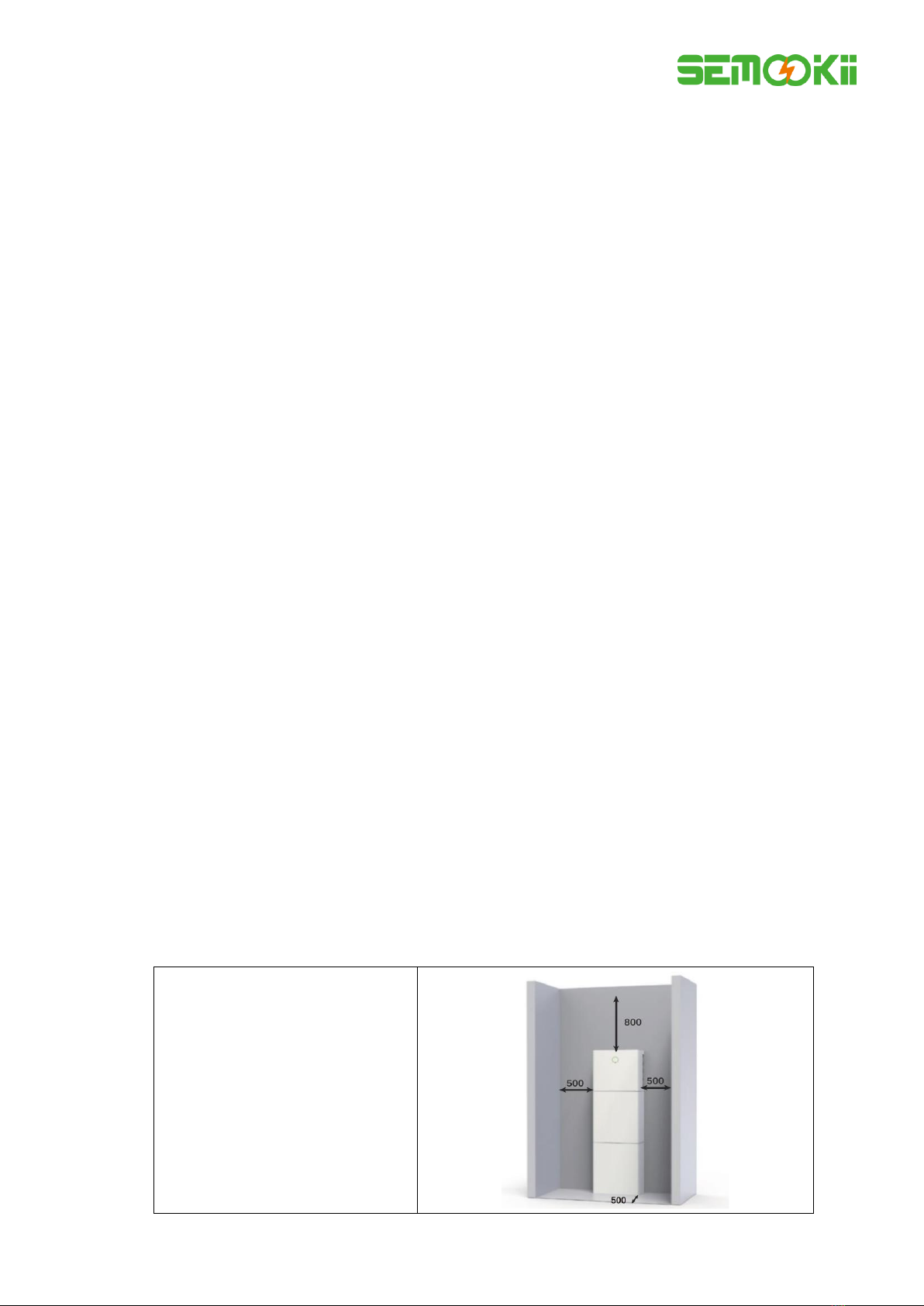
The following distances must remain empty:
(1) 500 mm beside the BESS;
(2) 800 mm above the BESS;
(3) 500 mm in front of the BESS.

Page 13 / 48
2.1.4 Select Mounting Location
For the BESS's protection and convenient maintenance, mounting location for The BESS should be selected carefully
based on the following rules:
Rule 1. The BESS should be installed on a solid surface, where is suitable for inverter's dimensions and weight.
Rule 2. The BESS installation should stand vertically or lie on a slop by max 2°(Pic 1).
Rule 3.Ambient temperature should be lower than 45°C.
Rule 4. The installation of The BESS should be protected under shelter from direct sunlight or bad weather like
snow, rain, lightning etc.
Rule 5. The BESS should be installed at eye level for convenient maintenance.
Rule 6. Product label on The BESS should be clearly visible after installation.

Page 14 / 48
2.2 Installation Steps
Unpacking the battery box and inverter box.
Unpacking the battery box
Unpacking the inverter box
2.2.1 Battery Box Installation

Page 15 / 48
For 10kWh BESS:
Step 1: Paste the cushions of the battery box.
Find four cushions from the inverter packaging accessory and paste them at the four corners of the bottom of
the battery box.
Step 2: Back plate pre-tightening
Remove the installation back plate from the inverter attachment package and pre-tighten the back plate to
the top of the battery box with two M4*10 screws, as shown in the figure below:
Step 3: Drilling holes
Put the pre-installed battery box in a specified position, so that it is close to the fixture, mark it according to
the hole position on the back plate, then rotate the back plate at an angle (or take the backboard away), and
drill holes at the fixture with Φ10mm.
Step 4: Fix expansion tube
Find the expansion screw from the inverter box accessory package and hammer it into the pre-drilled hole so
that its surface is flush with the wall.

Page 16 / 48
Step 5: Fix battery box and back plate
Rotate the back plate in place and spin the expansion pipe into the locking back plate with self-tapping
screws (note that the battery box is fixed with the back plate). Replace the battery box and align the
expansion pipe with the backboard hole, and then spin the self-tapping screws into it until the screw plane is
pressed on the back plate.
Step 6: Back plate pre-tightening
Remove the installation back plate from the inverter attachment package and pre-tight the back plate to the
top of the battery box with two M4*10 screws, as shown in the figure below.
Step 7: Install the second battery box
Put the second battery box smoothly on the top of the first battery box, and be careful not to hit the Back
plate.

Page 17 / 48
Step 8: Drilling holes
Put the pre-installed battery box in a specified position, so that it is close to the fixture, mark it according to
the hole position on the back plate, then rotate the back plate at an angle (or take the backboard away), and
drill holes at the fixture withφ10mm.
Step 9: Fix expansion tube
Find the expansion screw from the inverter box accessory package and hammer it into the pre- drilled hole
so that its surface is flush with the wall.
Step 10: Fix battery box and back plate
Rotate the back plate in place and spin the expansion pipe into the locking back plate with self- tapping
screws (note that the battery box is fixed with the back plate). Replace the battery box and align the
expansion pipe with the backboard hole, and then spin the self- tapping screws into it until the screw plane
is pressed on the back plate.

Page 18 / 48
How to fine-tune the battery box:
Item
Name
Torque
Note
1
Expansion screws
4 Nm
Tune up and down
2
Tune screws
3 Nm
Tune left and right
3
Fix screws
3 Nm
Tune front and back
Step 11: Fix the upper and lower connection plate. (Torque 2.5 Nm)

Page 19 / 48
2.2.2 Inverter Box Installation
Step 1: Take the inverter out of the box and place it smoothly on the battery box. Be careful not to damage the
cables of the inverter when moving it.
Step 2: Fix the upper and lower connection board to the inverter box
Pre-lock the back plate and inverter with M4*10L stainless steel screws, then lock the battery box and
inverter with a upper and lower connection plate, and finally lock the back plate with the screws of the
inverter. (Torque 2.5 Nm)

Page 20 / 48
Step 3: Install WiFi module
Find the WiFi module in the accessory package and insert it into the base, then tighten the Plastic nut.
Torque: 2.5N.m.
This manual suits for next models
7
Table of contents
Other SEMOOKII Storage manuals

Popular Storage manuals by other brands

Sony
Sony PCV-LX810 - Vaio Slimtop Computer Service manual

Seagate
Seagate ST1000NX0303 product manual

Western Digital
Western Digital Dual-option Backup USB 2.0 user manual

Sun Microsystems
Sun Microsystems Enterprise 4000 Rack Mounting Guide

Huawei
Huawei OceanStor S2600 manual

WiebeTech
WiebeTech MG8 user manual


Fujitsu
Fujitsu PRIMERGY LTO2 user guide

Toshiba
Toshiba HDDR200E02X Quick install guide

Digital Equipment
Digital Equipment TU56 Maintenance manual

GRASS VALLEY
GRASS VALLEY Profile XP PFR500/E instruction manual

Silicon Graphics
Silicon Graphics TP9400 RAID owner's guide

Maxell
Maxell DAT 160 80GB user guide