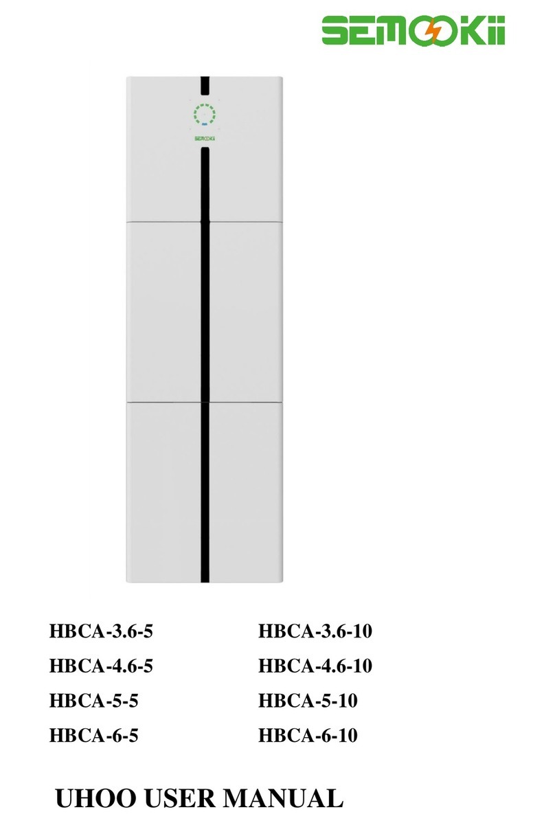
SEMOOKII HBC Series User manual


1/ 56
Copyright Statement
This manual is under the copyright of MPMC Powertech Corp. with all rights reserved. Please keep the manual
properly and operate in strict accordance with all safety and operating instructions in this manual. Please do not
operate the system before reading through the manual.
Version Information
Version
Date
Content
V01
12292022
New release

2/ 56
Contents
1. System Introduction............................................................................................................................................4
1.1 General Precautions...................................................................................................................................6
1.2 Parts List.....................................................................................................................................................7
1.2.1 Battery.........................................................................................................................................................7
1.2.2 Inverter........................................................................................................................................................8
1.2.3 Backup Box.................................................................................................................................................8
1.2.4 DC Box........................................................................................................................................................9
1.3 System Diagram .........................................................................................................................................9
1.4 Description................................................................................................................................................10
1.4.1 Battery.......................................................................................................................................................10
1.4.2 Inverter......................................................................................................................................................11
1.4.3 Backup box ...............................................................................................................................................12
1.4.4 DC box......................................................................................................................................................13
1.5 Liability Limitation......................................................................................................................................13
2. Installation Site and Environment ....................................................................................................................14
2.1 General .....................................................................................................................................................14
2.2 Restricted Locations .................................................................................................................................14
2.2.1 Inverter......................................................................................................................................................14
2.2.2 Battery.......................................................................................................................................................15
2.3 Installation.................................................................................................................................................16
2.3.1 Installation of batteries..............................................................................................................................16
2.3.2 Installation of inverter................................................................................................................................17
2.3.3 Installation of DC box ...............................................................................................................................18
2.4 Wiring........................................................................................................................................................19
2.4.1 Lithium Battery Connection.......................................................................................................................19
2.4.2 PV Connection..........................................................................................................................................24
2.4.2.1 PV Module Selection.............................................................................................................................24
2.4.2.2 PV Module Wire Connection.................................................................................................................24
2.4.3 Grid Connection........................................................................................................................................26
2.4.4 HOME LOAD Connection.........................................................................................................................27
2.4.5 BACKUP LOAD Connection.....................................................................................................................27
2.4.6 GENSET Connection................................................................................................................................28
2.4.7 External CT Connection............................................................................................................................28
2.4.8 GEN START connection ...........................................................................................................................29
2.4.9 Earth Connection (mandatory)..................................................................................................................29
3. System Operation.............................................................................................................................................30
3.1 Lithium Battery..........................................................................................................................................30
3.2 Power ON/OFF .........................................................................................................................................34
3.3 Inverter Operation and Display Panel.......................................................................................................34
4. LCD Display Icons............................................................................................................................................34
4.1 Main Screen..............................................................................................................................................34
4.1.1 LCD Operation Flow Chart .......................................................................................................................36
4.2 Solar Power Curve....................................................................................................................................37
4.3 Curve Page-Solar & Load & Grid..............................................................................................................39
4.4 System Setup Menu..................................................................................................................................40

3/ 56
4.5 Basic Setup Menu.....................................................................................................................................40
4.6 Battery Setup Menu..................................................................................................................................41
4.7 System Work Mode Setup Menu..............................................................................................................43
4.8 Grid Setup Menu.......................................................................................................................................45
4.9 Generator Port Use Setup Menu..............................................................................................................46
4.10 Advanced Function Setup Menu...............................................................................................................47
4.11 Device Info Setup Menu............................................................................................................................47
5. Limitation of Liability.........................................................................................................................................48
6. Appendix I ........................................................................................................................................................51
7. USER MANUAL for SOLARMAN Smart APP..................................................................................................53
7.1 Registration...............................................................................................................................................53
7.2 Create a Plant...........................................................................................................................................53
7.3 Add a Logger.............................................................................................................................................54
7.4 Network Configuration ..............................................................................................................................54

4/ 56
1. System Introduction
SEMOOKII HBC series residential energy storage system can provide clean solar energy for homes to reduce
your electricity bill, improve your energy independence by uninterruptedly switching faulty grid to battery power
supply.A small generator can be integrated to ensure system energy supply all the time.
Mode I: Basic
Mode II: With Generator

5/ 56
Mode III: With Smart-Load
Mode IV: AC Couple
The 1st priority power of the system is always the PV power, then 2nd and 3rd priority power will be the
battery bank or grid according to the settings.The last power backup will be the Generator if it is
available.

6/ 56
1.1 General Precautions
DANGER
Danger to life due to high voltages of the PV array, battery and electric shock.
When exposed to sunlight, the PV array generates dangerous DC voltage which will be present in the DC
conductors and the live components of the inverter. Touching the DC conductors or the live components can lead
to lethal electric shocks. If you disconnect the DC connectors from the system under load, an electric arc may
occur leading to electric shock and burns.
Do not touch uninsulated cable ends.
Do not touch the DC conductors.
Do not open the inverter and battery.
Do not wipe the system with damp cloth.
Have the system installed and commissioned by qualified people with appropriate skills only.
Prior to performing any work on the inverter or the battery pack, disconnect the inverter from all voltage
sources as described in this document.
WARNING
Risk of chemical burns from electrolyte or toxic gases.
During standard operation, no electrolyte shall leak from the battery pack and no toxic gases shall form. Even with
careful manufacturing process, if the battery pack is damaged or a fault occurs, it is possible that electrolyte may
be leaked or toxic gases formed.
Do not install the system in any environment of temperature below -10°C or over 50°C and in which humidity
is over 85%.
Do not touch the system with wet hands.
Do not put any heavy objects on top of the system.
Do not damage the system with sharp objects.
Do not install or operate the system in potentially explosive atmospheres or areas of high humidity.
Do not mount the inverter and the battery pack in areas containing highly flammable materials or gases.
If moisture has penetrated the system (e.g. due to a damaged enclosure), do not install or operate the system.
Do not move the system when it is already connected with battery modules.
Secure the system to prevent tipping with restraining straps in your vehicle.
The transportation of the HBC Series productions must be made by the manufacturer or a qualified person.
These instructions shall be recorded and repeated.
A certified ABC fire extinguisher with minimum capacity of 2kg must be carried along when transporting.
It is totally prohibited to smoke in the vehicle as well as close to the vehicle when loading and unloading.
For the exchange of a battery module, please request for new hazardous goods packaging if needed, pack
it and let it be picked up by the suppliers.
In case of contact with electrolyte, rinse the affected areas immediately with water and consult a doctor
without delay.
CAUTION
Risk of injury through lifting or dropping the system.
The inverter and battery are heavy. There is risk of injury if the inverter or battery is lifted incorrectly or dropped
during transport or when attaching to or removing from the wall.
➢Lifting and transporting the inverter and battery must be carried out by more than 1 person.

7/ 56
1.2 Parts List
Check the following parts list to ensure it is complete.
HBC Series productions delivers a total system separately on site to client, this consists of:
1.2.1 Battery
Item
Photo
Description
Quantity
1
Battery pack
1
2
wall mounting
bracket
1
3
wall hanging
bracket
2
4
expansion bolts
4

8/ 56
1.2.2 Inverter
Single Phase Inverter
1.2.3 Backup Box
AC Backup box
With breakers, Current transformer ,Plastic
expansion screws etc.

9/ 56
1.2.4 DC Box
DC box
With breaker, Plastic expansion screws
Power cables
Positive power cable (x3)
Negative power cable (x3)
Communication cable
Communication cable (x3)
screws
M6 (x6)
)
1.3 System Diagram
Item
Description
Model
1
Inverter
MIV-5S
2
Backup box
BB-01
3
DC box
HB-0352
4
Battery
pack
MF51100C

10 / 56
1.4 Description
1.4.1 Battery
1: Positive terminal
9: Parallel communication ports
2: Power indicator
10: Ground
3: Run indicator
11: Reset button
4: Alarm
12: DIP switch
5: SOC indicators
13: Dry contact
6: RS485 port
14: Negative terminal
7: CAN port
15: ON/OFF switch
8: RS232 port

11 / 56
1.4.2 Inverter
1: Inverter indicators
7: Meter port
13: Power on/off button
2: LCD display
8: Function Port
14: DC Switch
3: Function buttons
9: Parallel port
15: PV input with two MPPT
4: Battery input connectors
10: Generator input
16: Battery
5: RS 485 Port
11: Load (Backup load)
17: Temperature sensor
6: BMS CAN Port
12: Grid
18: WiFi Interface

12 / 56
1.4.3 Backup box
QF1: Grid input breaker
QF2: Home load breaker
QF3: Backup load breaker
QF4: GEN breaker

13 / 56
1.4.4 DC box
1.5 Liability Limitation
Any product damage or property loss caused by the following conditions manufacturer does not assume any direct
or indirect liability.
• System design and installation are not in compliance with standards and regulations;
• Failure to comply with the local safety regulations (VDE for DE, SAA for AU);
• Transport damage (including painting scratch caused by rubbing inside of packaging during shipping). A
claim should be made directly to shipping or insurance company in this case as soon as the
container/packaging is unloaded and such damage is identified;
• Failure to follow any/all of the user manual, the installation guide and the maintenance regulations;
• Improper use or misuse of the device;
• Insufficient ventilation of the device;
• The maintenance procedures relating to the product have not been followed to an acceptable standard;
• Force majeure (violent or stormy weather, lightning, overvoltage, fire etc.);
• Damages caused by any external factors.
1: Battery port 1-
8: Parallel copper bar +
2: Battery port 1+
9: Battery +
3: Battery port 2-
10: Battery port+
4: Battery port 2+
11: Battery port-
5: Battery port 3-
12: Battery -
6: Battery port 3+
13: Power indicator
7: Parallel copper bar -
14: Breaker

14 / 56
2. Installation Site and Environment
2.1 General
The system is installed in a room, the location is not obstructed by the structure of the building, fixtures and
fittings within the room. The system adopts natural ventilation. The location should be clean, dry and adequately
ventilated. The room’s entry doors and panels shall open in the direction of egress and allow unobstructed
access to the HBC for installation and maintenance purposes.
The following location are not allowed for installation:
• Habitable rooms;
• In ceiling spaces;
• Wall cavities;
• On roofs not specifically deemed suitable;
• Areas of access/egress;
• Under stairways;
• Under access walkways;
• Sites where the freezing point is reached, like garages, carports or other places;
• Sites with humidity and condensation over 85%;
• Sites which are salty and where humid air can penetrate;
• Earthquake areas –additional security measures are required here;
• Sites that are higher than 3000 meters above the sea level;
• Sites with explosive atmosphere;
• Sites with direct sunlight;
• Sites with extreme change of ambient temperature;
• Wet rooms;
• Sites with highly flammable materials or gases;
• Sites with a potentially explosive atmosphere.
2.2 Restricted Locations
2.2.1 Inverter
The inverters are designed for indoor and outdoor installation (IP65), to increase the safety, performance and
lifespan of the inverter, please select the mounting location carefully based on the following rules:
• The inverter should be installed on a solid surface, far from flammable or corrosion materials, where is
suitable for inverter’s weight and dimensions.
• The ambient temperature should be within -25℃~ 60℃(between -13 °F and 140°F).
• The installation of inverter should be protected under shelter. Do not expose the inverter to direct sunlight,
water, rain, snow, spray lightning, etc.
• The inverter should be installed vertically on the wall, or lean back on plane with a limited tilted angle.
Please refer to below picture.
• Leave the enough space around inverter, easy for accessing to the inverter, wiring and maintenance.

15 / 56
For proper air circulation to dissipate heat, allow a clearance of approx. 50cm to the side and approx. 50cm
above and below the unit. And 100cm to the front.
2.2.2 Battery
The batteries are designed for indoor installation (IP20), to increase the safety, performance and lifespan of
the battery, please select the mounting location carefully based on the following rules:
• The battery should be installed on a solid surface, far from flammable or corrosion materials, where is
suitable for battery’s weight and dimensions.
• The ambient temperature should be within -25℃~ 60℃(between -13 °F and 140°F).
• The installation of battery should be protected under shelter. Do not expose the battery to direct sunlight,
water, rain, snow, spray lightning, etc.
• The battery should be installed vertically on the wall.
• Leave the enough space around battery, easy for accessing to the battery, wiring and maintenance.

16 / 56
2.3 Installation
2.3.1 Installation of batteries
Unpacking the Battery
Take the battery out of the packaging box.
Note: the packaging box must be placed in accordance with the marking direction, the upward carton, the other
direction of the unpacking is wrong.
Step 1:Separate the wall mounting bracket from the battery pack, place the wall mounting bracket in a proper
position and close to the wall, mark the punching position with a marker, remove the wall mounting bracket and Drill
φ10 holes on the wall , 80mm deep and fix the wall mounting bracket on the wall with expansion bolts.
Step 2: Hang the battery pack on the wall mounting bracket and fix it with M5*16 screws on both sides.

17 / 56
Step 3: If multiple battery packs are used, Repeat Step 1 and 2. The distance between battery packs must be
at least 300mm.
2.3.2 Installation of inverter
Remember that this inverter is heavy! Please be careful when lifting out from the package. Drill φ10 holes on the
wall, 60mm deep.
1. Use a proper hammer to fit the expansion bolt into the holes.
2. Carry the inverter and holding it, make sure the hanger aim at the expansion bolt, and fix the inverter on the
wall.
3. Fasten the screw head of the expansion bolt to finish the mounting.

18 / 56
Inverter hanging plate installation
2.3.3 Installation of DC box
Place the DC box in a proper position and close to the wall, mark the punching position with a marker, remove
the DC box and Drill φ6 holes on the wall , 60mm deep and fix the DC box on the wall with Plastic expansion
screws.

19 / 56
2.4 Wiring
2.4.1 Lithium Battery Connection
Step 1: Make sure the circuit breaker of DC backup box is open. Connect the positive and negative cables
between the battery and the DC backup box respectively, and connect the other positive and negative cables
between to DC backup box and inverter respectively. When multiple batteries are used and need to be
connected in parallel, see below:
The cable specifications for the DC side of the inverter are as follows:
Single phase inverter
Table of contents
Other SEMOOKII Storage manuals
Popular Storage manuals by other brands

Dell
Dell EqualLogic PS Series Installation and setup
Convex
Convex RT Series Service manual

Regulus
Regulus PS 500 N25 Installation and operation manual
Tandberg Data
Tandberg Data NEO LTO-7 quick start guide
Rocstor
Rocstor ARCTICROC 4T Quick installation guide
Rocstor
Rocstor GUARDIAN 4RT Installation and configuration manual
