ITALIANO - 1/8MI002762-I
MI002762-I MI002762-I MI002762-I MI002762-I
MI002762-I MI002762-I ITALIANO - 5/8
ITALIANO - 2/8 ITALIANO - 6/8
ITALIANO - 3/8
ITALIANO - 4/8 ITALIANO - 8/8
I
SENECA s.r.l.
Via Germania, 34 - 35127 - Z.I. CAMIN - PADOVA - ITALY
Tel. +39.049.8705355 - 8705359 - Fax +39.049.8706287
THE INTERNATIONALCERTIFICATION NETWORK
R
ISO9001-2000
CONVERTITORE PER ALTA TENSIONE
AC/DC TRUE RMS
Z204
CARATTERISTICHE GENERALI
SPECIFICHE TECNICHE
Ingresso in tensione fino a 1200 V (scala DC), 850 V (scala AC), con scale pre-tarate
selezionabili da DIP-switch e la configurazione deve essere caricata su strumento
attraverso software di configurazione.
Uscita selezionabile: in corrente (0..20 mA) o, alternativamente, in tensione (0..10 V),
il cui valore è proporzionale al valore RMS della tensione di ingresso.
Elevata precisione: ingresso di classe 0.5, uscite in classe 0.1.
Range della frequenza in ingresso: DC..30 Hz-300 Hz.
Isolamento galvanico tra l'ingresso di tensione e gli altri morsetti pari a 4000 V.
Isolamento tra i morsetti di uscita e quelli di alimentazione di 1500 V.
Indicazione della presenza di alimentazione a mezzo di LED a pannello.
Il modulo Z204 misura il valore della tensione alternata e/o continua applicata ai morsetti di
ingresso, convertendolo in un segnale normalizzato in corrente 0..20 mA o in tensione
0..10 Vdc ai morsetti d'uscita, proporzionale al valore RMS dell’ingresso.
Le caratteristiche generali di cui gode sono le seguenti:
Alimentazione
Consumo
Ingresso Tensione
Uscita Corrente
Uscita Tensione
Deriva Termica
Tempo di Risposta
Condizioni Ambientali
Segnalazioni a LED
Grado di protezione
Peso, Dimensioni
Categoria di
sovratensione
Normative di
Conformità
10..40 V (polarità libera) o 19..28 V 50..60 Hz.
Isolamento verso i morsetti d'uscita: 1500 V.
Isolamento verso l’ingresso: 4000 V
DC AC,,
<1 W a 24 Vdc
Tensione continua 0..1200 Vdc, tensione alternata 0..850
Vac; si veda la tabella per la selezione della portata.
Impedenza ingresso: 800 k .
Frequenza: DC..30 Hz-300 Hz
Classe di precisione: 0.5
W
Range: 0..20 mA selezionabile tramite DIP-switch.
Resistenza massima di carico : 500 .
Classe di precisione: 0.1
W
Tensione continua: 0..10V selezionabile tramite DIP-switch
Resistenza minima di carico : 1 k .
Classe di precisione: 0.1
.
W
100 ppm/K.
Per una variazione a gradino: 1 s dal 10 al 90 %.
Temperatura di funzionamento: -20..65°C, temperatura di
stoccaggio: -20..85°C, umidità 30÷90 % @ 40°C non
condensante.
Alimentazione (verde), errore interno (giallo), Rx/Tx (rosso).
IP20.
140 g, 100 x 112 x 17.5 mm.
I
I,
I, fino a 600 Vrms;
Per tensioni/classi superiori, provvedere a una limitazione di
sovratensione esterna al dispositivo
fino a 1000 Vrms
EN61000-6-4 (2007): (emissione elettromagnetica, ambiente
industriale)
EN61000-6-2 (2006): (immunità elettromagnetica, ambiente
industriale)
EN61010-1 (11-2001): (sicurezza)
Tutti i circuiti devono essere isolati con doppio isolamento dai
circuiti sotto tensione pericolosa. Il trasformatore di
alimentazione deve essere a norma EN60742: “Trasformatori
di isolamento e trasformatori di sicurezza”.
ATTENZIONE!
PRIMA DI MANOVRARE I DIP-SWITCH ACCERTARSI DI AVERE
DISCONNESSO TUTTI I CIRCUITI A TENSIONI PERICOLOSE.
La portata dello strumento è stabilita dall'impostazione dei DIP-switch SW1 (2 vie); la
tabella sottostante riporta le combinazioni utili per le portate pretarate.
MI002762-I ITALIANO - 7/8
Indirizzo fisso 03
Indirizzo fisso 04
Indirizzo fisso, come da rappresentazione binaria.
Indirizzo fisso 63
Indirizzo fisso 02
Parametri di comunicazione da EEPROM (*)
Indirizzo fisso 01
SW2 43
X
5
X
6
X
7
X
8
X X
INDIRIZZO
57600 Baud
38400 Baud
19200 Baud
9600 Baud
1SW2 2
BAUD RATE
SW2 - PARAMETRI DI COMUNICAZIONE
0-1200 Vdc
0-850 Vdc
0-500 Vdc
0-150 Vdc
1SW1 2
SCALE DI INGRESSO (valori limite massimi)
SW1 - SCALA DI INGRESSO
0-100 Vac
0-350 Vac
0-600 Vac
0-850 Vac
SCALA DC SCALA AC
Lo strumento è configurato in fabbrica con fondo scala 1000Vdc.
Esempio: se il nuovo fondo scala caricato da software è 680 Vdc,
impostare i Dip-Switch SW1-1=»0», SW1-2=»1» (corrispondente a 0-850 Vdc).
Per cambiare la scala di ingresso, impostare i Dip-Switch SW1 come illustrato nella
precedente tabella e caricare la configurazione attraverso il software di
configurazione (Easy, Z-NET).
Per ottenere la migliore risoluzione, configurare i Dip-Switch SW1 selezionando la
scala di ingresso inferiore (tra le quattro nella precedente tabella) che comprende il
nuovo fondo scala.
ON
OFF
1
SW3 2
TERMINATORE RS485
SW3 - TERMINATORE
Terminatore (120 )W
Uscita analogica: tensione o corrente ritrasmessa
RS485
1
SW4
SW4 - GRANDEZZA DISPONIBILE AI MORSETTI 4, 5, 6
Grandezza disponibile ai morsetti 4, 5, 6
TERMINATORE RS485
MORSETTI 4-5-6
ISOLAMENTI
Power
supply
RS485
GND
AB
AC, DC
IN
4000 V
OUT
RS232
4000V
In tutte le tabelle seguenti l’indicazione corrisponde a DIP-switch in 1 (ON);
nessuna indicazione corrisponde a DIP-switch in 0 (OFF)
IMPOSTAZIONE DEI DIP-SWITCH
Indicazioni tramite LED sul pannello frontale
LED PWR (VERDE)
Acceso
Significato
Indica la presenza dell’alimentazione.
LED ERR (GIALLO) Significato
Acceso Errore interno.
LED RX (ROSSO)
Acceso
Significato
Indica la ricezione di dati sulla porta di comunicazione RS485.
LED TX (ROSSO)
Acceso
Significato
Indica la trasmissione di dati sulla porta di comunicazione RS485.
Smaltimento dei rifiuti elettrici ed elettronici (applicabile
nell’Unione Europea e negli altri paesi con servizio di raccolta
differenziata).Il simbolo presente sul prodotto o sulla sua confezione indica che il
prodotto non verrà trattato come rifiuto domestico. Sarà invece consegnato al centro di
raccolta autorizzato per il riciclo dei rifiuti elettrici ed elettronici. Assicurandovi che il
prodotto venga smaltito in modo adeguato, eviterete un potenziale impatto negativo
sull’ambiente e la salute umana, che potrebbe essere causato da una gestione non
conforme dello smaltimento del prodotto. Il riciclaggio dei materiali contribuirà alla
conservazione delle risorse naturali. Per ricevere ulteriori informazioni più dettagliate Vi
invitiamo a contattare l’ufficio preposto nella Vostra città, il servizio per lo smaltimento dei
rifiuti o il fornitore da cui avete acquistato il prodotto.
Questo documento è di proprietà SENECA srl. La duplicazione e la riproduzione sono vietate, se non autorizzate. Il
contenuto della presente documentazione corrisponde ai prodotti e alle tecnologie descritte. I dati riportati potranno
essere modificati o integrati per esigenze tecniche e/o commerciali. Il contenuto della presente documentazione viene
comunque sottoposto a revisione periodica.
Banda passante A 1 kHz, errore pari a 1.5%
PANNELLO FRONTALE
ATTENZIONE!
PRIMA DI EFFETTUARE QUALSIASI COLLEGAMENTO ALLO
STRUMENTO ACCERTARSI DI AVERE DISCONNESSO TUTTI I CIRCUITI A
TENSIONI PERICOLOSE.
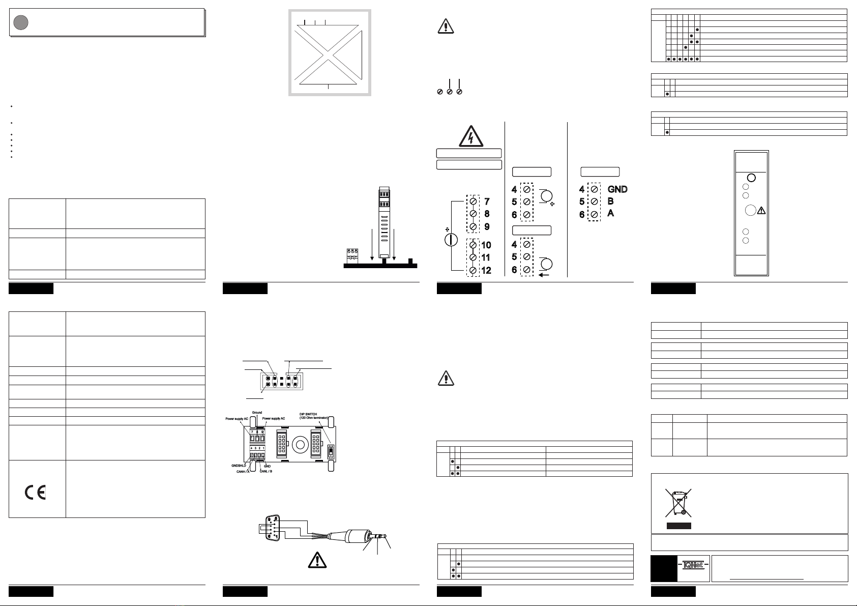
COLLEGAMENTI ELETTRICI
La tensione di alimentazione deve essere compresa tra
(polarità indifferente), .
.
E' necessario proteggere la sorgente di alimentazione da
eventuali guasti del modulo mediante fusibile
opportunamente dimensionato.
10..40 V 19..28 V
DC AC
I Iimiti superiori non devono essere superati, pena
gravi danni al modulo
2 3
ALIMENTAZIONE
19 - 28 Vac
10 - 40 Vdc
<1 W @ 24Vdc
+
12
11
10
9
8
7
INGRESSO
Max 1200 Vdc
Max 850 Vac
Tensione ingresso
True RMS
USCITA
6
5
4
6
5
4
+
4 - 20 mA
V
mA
0 - 10 V
Uscita in corrente
o tensione
( )SW4-OFF
COMUNICAZIONE
Porta COM
( )SW4-ON
6A
4
5
GND
B
RS485
Collegare il polo «+» della tensione di ingresso, indifferentemente, in uno dei morsetti 7, 8,
9 (tra loro equipotenziali).
Collegare il polo «-» della tensione di ingresso, indifferentemente, in uno dei morsetti 10,
11, 12 (tra loro equipotenziali).
Il modulo è progettato per essere montato su guida DIN 46277, in posizione verticale. Per
un funzionamento ed una durata ottimali, assicurare un’adeguata ventilazione, evitando di
posizionare canaline o altri oggetti che occludano le feritoie di ventilazione. Evitare il
montaggio dei moduli sopra ad apparecchiature che generano calore; è consigliabile il
montaggio nella parte bassa del quadro.
NORME DI INSTALLAZIONE
Collegamenti Elettrici
PORTA SERIALE RS485 EALIMENTAZIONE
I collegamenti elettrici relativi all’alimentazione sono disponibili sia da morsetti sia
utilizzando il bus per guida DIN Seneca. I collegamenti relativi al bus RS485 sono invece
disponibili utilizzando il bus per guida DIN o, settando il Dip-switch SW4 a «1», attraverso
morsetti.
Come illustrato in figura:
1) Inserire il connettore posteriore IDC10
del modulo su uno slot libero della guida
DIN (l’inserimento è univoco essendo i
connettori polarizzati).
2) Per fissare il modulo nella guida DIN
stringere i due ganci posti ai lati del
connettore posteriore IDC10.
1
Jack stereo 3.5 mm
DB9-F
GND Rx
Rx
Tx
GND
5
6
9
PORTA SERIALE RS232
Il cavo di connessione DB9 Jack stereo 3.5 mm può essere assemblato come indicato
nella figura seguente, oppure acquistato come accessorio.
Tx
ALIMENTAZIONE ED INTERFACCIA MODBUS
Alimentazione ed interfaccia Modbus sono disponibili utilizzando il bus per guida DIN
Seneca, tramite il connettore posteriore IDC10, o l’accessorio Z-PC-DINAL2-17,5.
In figura si riporta il significato dei
vari pin del connettore IDC10 nel
caso in cui si desideri fornire i
segnali direttamente tramite esso.
Nel caso di utilizzo dell’accessorio
Z-PC-DINAL , i segnali
possono essere forniti tramite
morsettiere.
In figura si riporta il significato dei
vari morsetti e la posizione del DIP-
switch (presente in tutti i supporti
per guida DIN elencati in Accessori)
per la terminazione della rete CAN
(non usata nel caso di rete
Modbus).
GNDSHLD: Schermo per
proteggere i cavi di connessione
(consigliato).
2-17,5
Connettore Posteriore (IDC10)
Utilizzo Accessorio Z-PC-DINAL2-17,5
RS485 GND
RS485 A
RS485 B
Power Supply AC +
Power Supply AC-
IDC 10
1
REGISTRI MODBUS SIGNIFICATIVI
Indirizzo
40047
Nome Significato
40048
Valore RMS della tensione in ingresso (floating point, bit
più significativi)
V_RMS (MSB)
V_RMS (LSB) Valore RMS della tensione in ingresso (floating point, bit
meno significativi)
PWR
ERR
RX
TX
COM
123
456
S
Z204
789
10 11 12
IMPORTANTE
Utilizzare la porta seriale RS232 solo dopo aver scollegato l’ingresso in alta tensione.