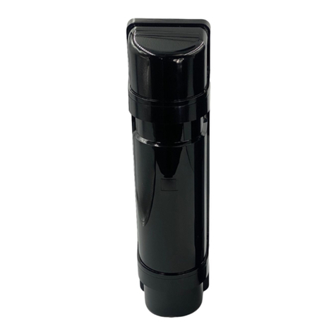
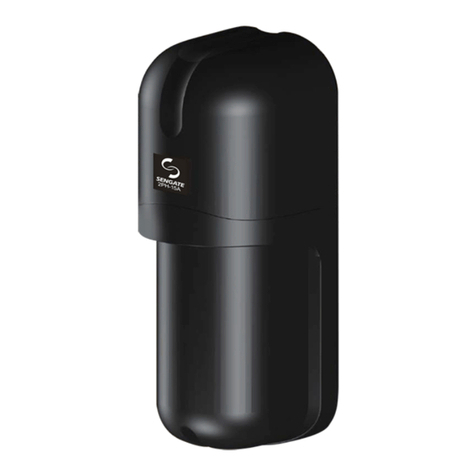
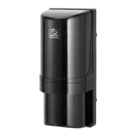
Sengate 4PH-50TA User manual

1
INSTRUCTION MANUAL
Thanks for purchasing product. Read this instruction manual before using the product to make sure that you u e it correctly.s
4PH-50TAI / 4PH100TAI / 4PH-200TAI
4PH-50TA / 4PH100TA / 4PH-200TA
PRODUCT PARTS:
●Large and expanded protection range.
●
●
Quad Photoelectric Beam 4PH-50 / 100 TA/TAI with detection range at 50m , 100m as well. / 200 and 200m
●The product is designed with FDM ( Frequency-Division Multiplexing ) TDM ( Time-Division Multiplexing ) technology to prevent interference.
FEATURES
4 sets could be stacked and operated on the same pole with same direction by total four(4) duals and sixteen(16)
beams protection.
4PH-50 / 100 / 200 TA/TAI
Horizontal angle
fine adjustment Screw
Lens
Lens
Horizontal angle
coarse adjustment
Screw
Horizontal angle
fine adjustment Screw
Horizontal angle
coarse adjustment
Screw
Panel
Vertical angle
adjustment Screw
Vertical angle
adjustment Screw
View Finder
View Finder
Unit Base (ATI)
Main Base
Mounting Plate
U-Shaped
Brackets
Cover Locking Screw
Main Base
Mounting Piece
MAIN BASE
4PH-XXXTAI
(4PH-XXXTA)
8
8
2
Accessories Q'ty
Hex Screws
4x25
Hex Nuts M4
Attenuation
Sheets
Optional Accessory
(4PH-XXXTAI)
8
8
4
2
Screws 4x20
Screws M4x30
U-Shaped
Brackets
Attenuation
Sheets
HT-200 Heating Unit
Accessories Q'ty
Optional Accessory
HT-120 Heating Unit
50M/100M/200M QUAD PHOTOELECTRIC BEAM SENSOR
( )
TA TAI /
Cover
4PH-XXXTA
PARTS DESCRIPTION

2
EXAMPLE OF INCORRECT INSTALLATION
POSITION AND RATING OF TERMINALS
INSTALLATION & PRECAUTIONS:
Installation in areas where objects
(trees, clothes …etc.) can obstruct
the optical axis.
Installation in location where strong light
(ex. vehicle headlights) can directly enter
the optics facility of Receiver.
Installation in location where the product
may be splashed by dirty water or direct
sea spray.
Installation in an unsteady location.
Installation in location where long time strong and
direct sunlight would age the product easily.
When installing, need to make sure if there is
other beam sources to enter and affect
transmitting from 4PH-50 100 TAI.
any
the / / 200
PROTECTION DISTANCE
4PH- 50 TA / 4PH- 50 TAI : 50m Outdoor
4PH-100 TA / 4PH-100 TAI : 100m Outdoor
4PH-200 TA / 4PH-200 TAI : 200m Outdoor
The distance between Transmitter and Receiver
should within following spec :
±90°
±10°
ALIGNMENT ANGLE
Coarse adjustments can be made
by moving
range of horizontally,
between -10 and +10 by
pushing it forwards or backwards.
the swivel base with
the ±90°
the inclination of the lens can be
switch ° °
COVERAGE OF LIGHT BEAM
The coverage of light beam can be calculated
by following formula :
Width (A ) = 0.025 x Distance ( L )
Width (A )
Receiver
Distance ( L )
Transmitter
1 2 34567
COM
NC.
NO.
NC.
+_
8
9
10
COM
NC.
NO.
1 2 3456
NC.
+_
SYN.-SYN.+
< >TRANSMITTER < >RECEIVER
Power
DC 12V-30V
( Non-polarity )
Sync Signal
Output/Input
Tamper Switch Output
Dry Connect NC.
0.2A / 28 VDC
Power
DC 12V-30V
( Non-polarity )
Alarm Output
Dry Connect NO/NC
0.2A / 28 VDC
Environmental Output
Dry Connect NO/NC
0.2A / 28 VDC
WIRING METHOD:
TRANSMITTER PANEL RECEIVER PANEL
Wiring
Terminals
1. Beam Channel Switch
2. Master / Slave Switch
1. Tamper Switch
2. LED Indicator
Response Time Adjustment
1.Weak Signal (LED)
Alarm LED
Monitor +
Monitor -
NAMES OF FUNCTION SETTING SECTION
SYNC Single (LED)
Transmitter Power Switch
1. Beam Channel Switch
2. Master / Slave Switch
1. Tamper Switch
2. LED Indicator
Wiring
Terminals
50 m
100 m
200 m
1.25 m
2.50 m
5.00 m
Distance (L) Width (A)
Tamper Switch Output
Dry Connect NC.
0.2A / 28 VDC

3
INSTALLATION METHOD:
CH_A
Slave-3
CH_A
Slave-2
CH_A
Slave-1
CH_A
Master
1 1 11
1 1 11
1 1 11
1 1 11
2 2 22
2 2 22
2 2 22
2 2 22
3 3 33
3 3 33
3 3 33
3 3 33
4 4 44
4 4 44
4 4 44
4 4 44
CH_B
Slave-3
CH_B
Slave-2
CH_B
Slave-1
CH_B
Master
CH_A CH_B
Receiver Receiver
Transmitter Transmitter
T/T Sync Signal
WIRING DIAGRAM
Control Panel
}
}
Power
Alarm Signal
A. Loosen the cover fixing screws,
and remove the sensor body.
B. POLE MOUNTING:
B-1 Choose proper length pole with
42 - 45 mm O.D.
B-2 Drill a hole on the pole where the
sensor would be mounted.
:
:
B-3 ttach the included M4x30 screws to fix
mounting plate U-Shaped Bracket
on the pole.
: A
and
B-4 Pull out the wire through the mounting
plate and sensor. Use the sensor fixing
screws to fix the sensor body to the
mounting plate.
B-5 Refer to section 3. WIRE METHOD
to connect the wire.
:
:
〝 〞
4-3 Place the M4x25 hex screws &
to the mounting piece and
the aluminum profile.
4-4 Fix and attach the beam device
the mounting piece.
:
nuts
slide it on
:
on
4-5 : Proceed the wiring.
4-6 Refer to ″8. ALIGNMENT AND OPERATION
, do the alignment, adjustment and testing as well.
4-7 Mount the polycarbonate profile, inserting and
sliding it along the aluminum, then place the top
cover on the aluminum profile and tighten bolts
fully.
: ADJUSTMENT″
:
B-6 Refer to section 8. ALIGNMENT AND
OPERATION ADJUSTMENT to adjust
the optical axis.
B-7 Attach the transmitter and receiver covers,
and fix them in place the cover
fixing screws.
:
:
using
〝
〞
B-8 Back to back pole installation. Fix two
U-Shaped brackets in layers on a pole,
two units can be installed back to back
on a pole at the same height.
:
4PH-XXXTA
4PH-XXXTAI
4-1 : Follow the instruction to install the
alum-extrusion and side brackets
the ground, and then proceed
photo beam device installation.
4-2 Take off the mounting piece from
beam device.
on
the
:
the

4
BEAM CHANNEL CHANGEOVER FUNCTION & MASTER/SLAVE SWITCH:
5-2 According to beam quantity, refer to the following drawings ( 1,2,3,4,5 ) for beam installation in the site.
5-3 According to the condition, follow the Fig. 5-2/ 5-3 to set Beam Channel and Master/Slave position.
5-1 When the existing range is shorter than product spec, then it only needs lower power for operation, please refer
to Fig 5-1 for the setting.
● The Beam Channel and Master/Slave position setting should be identical on both Transmitter and Receiver.
(TRANSMITTER PANEL)
(TRANSMITTER)
(TRANSMITTER)
※ "Master"NOTE: The first thing is to set position on both Transmitter and Receiver.
(TRANSMITTER PANEL)
1. BEAM CHANNEL SWITCH
2. MASTER/SLAVE SWITCH
SYNC SIGNAL(LED)
TRANSMITTER POWER SWITCH
1. BEAM CHANNEL SWITCH
2. MASTER/SLAVE SWITCH
SYNC SIGNAL(LED)
TRANSMITTER POWER SWITCH
TRANSMITTER POWER SWITCH
H
L
TRANSMITTER
POWER SWITCH
(RECEIVER PANEL)
1. BEAM CHANNEL SWITCH
2. MASTER/SLAVE SWITCH
WEAK SIGNAL(LED)
RESPONSE TIME ADJUSTMENT
ALARM LED
( )TRANSMITTER / RECEIVER
Master Slave-1
Slave-2 Slave-3
CH-A
CH-B
1. BEAM CHANNEL
SWITCH
2. MASTER/SLAVE
SWITCH
100 m
75 m
200 m
150 m
50 m
37 m
H
L
4PH-50TAI
4PH-100TAI 4PH-200TAI
Power
Status
Distance
Model
(Fig. 5-1)
When doing ONE TO ONE installation, refer to Fig 5-3,
setting Master in position." "
CH_A
(Master)
(Drawing 1)
TRANSMITTER RECEIVER
BEAM CHANNEL
SWITCH
CH_A
DIP-SW
CH_B
-1
STATUS
CHANNEL
( Fig. 5-2 )
MASTER/SLAVE
SWITCH
DIP-SW
Master
Slave-1
Slave-2
Slave-3
-2 -3
STATUS
MASTER
/ SLAVE
( Fig. 5-3 )
ONE TO ONE
TWO TO TWO
When doing TWO TO TWO installation, refer to Fig 5-3, firstly,
setting in position,the second unit setting with Slave-1,
or Slave-2 or Slave-3.
"Master"
CH_A
CH_A
(Master)
(Slave-1)
(Drawing 2)
TRANSMITTER RECEIVER
CH_A
CH_A
CH_A
(Master)
(Slave-1)
(Slave-2)
(Drawing 3)
TRANSMITTER RECEIVER
THREE TO THREE
When doing THREE TO THREE installation, refer to Fig 5-3, firstly,
setting in position,the second third units setting with
Slave-1 Slave2 or Slave-1 Slave-3 or Slave-2 Slave-3.
"Master"/
/ / /

5
FUNCTIONS:
CH_B CH_B CH_ACH_A
(Master)
(Slave-1)
(Slave-2)
(Slave-3)
TRANSMITTER TRANSMITTERTRANSMITTER TRANSMITTERRECEIVER RECEIVER RECEIVERRECEIVER
(Drawing 4)
When doing FOUR TO FOUR installation, refer to Fig 5-3, firstly, setting in position,
the second third four units setting with Slave-1, Slave2 and Slave-3 sequentially.
"Master"
/ /
FOUR TO FOUR
SQUARE PROTECTION
Please see the drawing for square protection installation.
(Drawing 5)
Master
Master
Master
Master
Slave-1
Slave-1
Slave-1
Slave-1
Slave-2
Slave-2
Slave-2
Slave-2
Slave-3
Slave-3
Slave-3
Slave-3
CH_A CH_B
RECEIVERRECEIVER
CH_B CH_B
TRANSMITTER TRANSMITTER
CH_A CH_B
RECEIVER RECEIVER
CH_A CH_A
TRANSMITTER TRANSMITTER
● RECEIVER(RX) WEAK SIGNAL(LED)
1. When the receiving signal is weak,
the SIGNAL(LED) would blink,
the re-align is required.
2. If the receiving signal is getting more
weak, the SIGNAL(LED) would blink
faster.
●
the SYNC SIGNAL would follow the orders of Master, Slave-1, Slave-2, Slave-3 to
Blink / ON-OFF.
2. When the beam(TX) is mistakenly setting with duplicated Master, then that would cause
one LED light of the sensor doesn't stop, and the other one LED keeps blinking.
3. When the Slave beam(TX) doesn't connect SYNC with Master beam well, the LED light
won't stop.
TRANSMITTER(TX) SYNC SIGNAL INDICATOR :
1. When the sensor installed and the Master / Slave-1, 2, 3 setting properly as well,
(TRANSMITTER PANEL)
(RECEIVER PANEL)
a. Detection is normal.
b. LED (TX) blinks orderly from upside to downside.
(Master)
(Slave-1)
(Slave-2)
(Slave-3)
Transmitter
(Master)
(Slave-1)
(Slave-2)
(Slave-3)
Receiver
a. The orders of Master / Slave on TX and RX should
be identical, if not, when aligning the Slave-2,
Slave-3 on TX ( see the drawing above ), the test
voltage on RX won't response.
(Master) (Master)
(Slave-1) (Slave-1)
(Slave-2) (Slave-3)
(Slave-3) (Slave-2)
Transmitter Receiver
a. Detection is normal.
b. LED (TX) blinks orderly from upside to downside.
(Master)
(Slave-1)
(Slave-3)
(Slave-2)
Transmitter
(Master)
(Slave-1)
(Slave-3)
(Slave-2)
Receiver
a. The orders of Master / Slave of TX and RX should
be identical, if not, when aligning the Slave-2, 3
on TX ( see the drawing above ), the test voltage
on RX won't response.
b. If Slave-2 on TX is duplicated setting, even one of
Slave-2 is blocked which still won't cause alarm.
c. LED light doesn't stop.
(Master)
(Slave-1)
(Slave-2)
(Slave-2)
Transmitter
(Master)
(Slave-1)
(Slave-2)
(Slave-2)
Receiver
SYNC SIGNAL(LED)
1. BEAM CHANNEL SWITCH
2. MASTER/SLAVE SWITCH
TRANSMITTER POWER SWITCH
WEAK SIGNAL(LED)
1. BEAM CHANNEL SWITCH
2. MASTER/SLAVE SWITCH
ALARM LED
When it is very misty because of fog, the
signal of Receiver is dropping seriously,
the Environment diagnostic function
be initiated.would
● Environment Detection :

6
RESPONSE TIME ADJUSTMENT:
ALIGNMENT AND OPERATION ADJUSTMENT:
Monitor Output Voltage Value
MONITOR JACK OUTPUT
ALIGNMENT LEVEL
More than 4.5V
3.0V to 3.5V
3.5V to 4.0V
4.0V to 4.5V
Less than 2.5V
BEST
GOOD
PRETTY GOOD
RE-ALIGN
MARGINAL
50
100
150
500
(ms)
200 300
400
● The beam interruption time adjustment is on Receiver Unit only. Speeds shown below are the maximum detectable
speeds for each setting.
Response time adjustment volume
( Receiver )
50ms 100ms 300ms 500ms
Running at full speed Running at slow speed Walking normally Walking slowly
※NOTE:In order to get the optimum setting for response time adjustment, operation testing is absolutely
required after installation.
8-1:Apply power to both Transmitter and Receiver.
8-2 Looking thru the view finder, locate the other detector in the
center of the sights vertically and horizontally by fine/coarse
adjusting.
:
1View Finder
2
3
Horizontal adjustment
( coarse )
Horizontal adjustment
( fine )
4 Vertical adjustment ( fine )
Red Meter
Probe (+)
Black Meter
Probe (-)
8-3:Connect the volt-meter ( with DC10V ) to monitor jack input
the Receiver's Monitor (+) AND (-) ( Red apply to
Black apply to Monitor - )
on
Monitor +,
8-4: Place attenuation sheet on both Transmitter and Receiver ( Lower Lens ).
8-5: Use the adjustment screw to find adjust the Upper Lens ( on Transmitter )
horizontally and vertically until the monitor reaches the highest number.
8-6: Use the adjustment screw to find adjust the Upper Lens ( on Receiver )
horizontally and vertically until the volt-meter reaches the highest number.
8-7: Repeat the section of 8-5, 8-6 to obtain the maximum voltage from the
monitor jack.
Adjust the Upper Lens
Attenuation
Sheet
8-8: Place attenuation sheet on both Transmitter and Receiver ( Upper Lens ).
8-9: Use the adjustment screw to find adjust the Lower Lens ( on Transmitter )
horizontally and vertically until the monitor reaches the highest number.
8-10: Use the adjustment screw to find adjust the Lower Lens ( on Receiver )
horizontally and vertically until the volt-meter reaches the highest number.
8-11: Repeat the section of 8-9, 8-10 to obtain the maximum voltage from
the monitor jack.
8-12: Taking off the attenuation sheet and meter probe as well.
The installation is done.
Adjust the Lower Lens
Attenuation
Sheet
NOTE:
1. The output value of alignment should be reaching 3.2V at least.
2. Above readings is under attenuation sheet operation.
3. Carefully remove the attenuation sheet and check the voltage from the
monitor jack again.

7
SPECIFICATIONS:
9
TROUBLESHOOTING:
STATUS CAUSE REMEDY
Sync LED does not light
( Transmitter )
Sync LED does not stop
( Transmitter )
Alarm LED does not stop
( Receiver )
Alarm LED does not light even if
the infrared beam is obstructed.
( Receiver).
Weak Signal LED continues
to be blink.
( Receiver )
Alarm Ons and Offs
( Receiver )
No response on Alignment
Operation
1. Power is not on.
2. Poor wiring or breaking of wire, short.
1. Poor wiring on SYNC Signal, or breaking of wire, short.
2. Sync signal connected with wrong polarity.
3. Wrong Channel setting.
4. Two(2) Transmitters both setting as Master.
1. Alignment is not aligned correctly.
1. Alignment is not aligned correctly.
2. Transmitter and Receiver Installation distance exceed
required spec.
3. Infrared power on Transmitter set with Low Power.
4. Power source on Transmitter is too low to support
infrared signal.
1. The units setting on same Channel, however not facing
the same direction.
2. Alignment is not aligned correctly.
3. Transmitter and Receiver cover is dirty.
4. Power is too low to activate the relay.
1. Wrong Master Slave Switch setting.
2. Wrong Channel setting.
/
1. Connect the power source.
2. Check the wiring
1. Check the wiring of “ SYNC Signal “.
2. Check the polarity on Sync signal.
3. Check DIP-SW, Channel settings on Receiver.
4. Check DIP-SW, one Transmitter only allow one master.
1. Re-align Transmitter and Receiver.
1. Re-align Transmitter and Receiver.
2. Check the installation distance meet required spec.
3. Refer to the instruction for Infrared Power setting.
4. Check the power source on Transmitter.
1. Re-set the channel properly
2. Re-align Transmitter and Receiver.
3. Clean using a soft cloth.
4. Check the power source.
.
1. Wrong Channel (A-B) setting.
2. The Master Slave-1, 2, 3 setting on TX is different
from RX.
/
1. Check if the Channel (A-B) / DIP-SW setting is identical on
both TX and RX.
2. The order of Master Slave-1, 2, 3 should be identical on both
TX and RX.
/
1. Channel (A-B) setting should be identical on both TX and RX.
2. Master Slave 1, 2, 3 setting on TX and RX should be identical. /
Model No. Model No.
Items Items
Detection Range Response Time
Beam Adjustment
Mounting Positions
Functions
Ambient Temperature
Wiring
Environment Humidity
Weight
Optional Accessory
Standard
Accessories
Dimension (mm )
Max. Arrival Distance
Min. Arrival Distance
Supply Voltage
Current Consumption
( Transmitter )
Current Consumption
( Receiver )
Infrared Beam
Infrared Signal
Detection System
Alarm Output
Tamper Output
Attenuation
Indicator
Alarm LED
T/T Sync LED
Environmental
Output
5 (m)0
50 0 (m)
1 0 (m)
14 mA (max.) 16 mA (max.) 18 mA (max.)
a. Norm : 36mA (Max.)
b. When Environmental Relay operating : 55mA (Max.)
1. Two(2) channels ( CH_A / CH_B) is selectable.
2. Master / Slave-1, -2, -3 function is selectable.
3. Transmitter power ( H / L ) is selectable.
4. When the cover attached, all the LED would be off
for power saving.
7. ʺ Attenuation ʺ LED lights : when Environment
diagnostic function is initiated.
5. The Auto Gain Lock function only operates when the
front cover attached on the sensor body properly.
6. It's selectable to stack four(4) sensors on the same
pole and same direction facing.
4 Infrared Photoelectric Beams.
10 0 (m)
100 0 (m)
25 (m)
20 0 (m)
200 0 (m)
5 0 (m)
Infrared beam interruption system
Dry contact relay NC / NO. 0.2A / 28VDC
Interuption Time : 1.5 seconds
When the infrared signal dropping caused by
snow or fog.
heavy
Dry contact relay NC / NO A / 28VDC. 0.2
Micro SW Dry contact relay NC A / 28VDC
Action : When cover is detached.
. 0.2
When Beam Channel and Master / Slave setting
properly, Red LED would ON-OFF orderly.
Outdoor
Horizontal ,Vertical ±10°±90°
-25°C ~ +55°C
95%
Terminals
W3.94" x H15.35" x D3.93"
(W )100.0 x H390.0 x D99.8 mm
Red LED ( Receiver ) lights : when beam is alarm is initiated.
U-Shaped Brackets x 4、Attenuation Sheet x 2
x 8
Screws ( M4 x 30 mm ) x 8
Screws ( 4 x 20 Self tapping )
Heating Unit : HT-200
50 msec – 500 msec ( adjustable )
DC12V~30V ( Non-Polarity )
.
FDM ,TDM, 890m ( Pulsed Wave-length )
Yellow LED keeps ON and OFF, when the signal get
weaker, the ON-OFF get faster.
4PH-50TA
4PH-50TAI
4PH-50TA
4PH-50TAI
4PH-100TA
4PH-100TAI
4PH-100TA
4PH-100TAI
4PH-200TA
4PH-200TAI
4PH-200TA
4PH-200TAI
4PH-XXXTA : 4PH-XXXTAI : 1190 grams 2870 grams /

8
Web Site : http : // www.sengate.com
E-mail : service @ sengate.com
No.4-46, Fengren Rd., Renwu Dist., Kaohsiung City 81459, Taiwan (R.OC)
TEL : +886-7-3721111~6 FAX: +886-7-3728650
EXTERNAL DIMEN IONS: S
NOTE :
1. This unit is designed to detect intruder and activate alarm control panel. Being only a part of complete system,
we cannot assume responsibility for theft or damages, should it occur.
2. Specifications and design are subjected to change without prior notice.
3. No take apart the product improperly, which possibly cause the damage.
No:A063B02-01
Unit: [inch mm]
5.83"[148]
2.43"[61.6]
3.29"[83.5] 0.17"[4.4]
3.54"[89.9]
14.02"[356]
9.35"[237.5]
0.97"[24.5] 0.97"[24.5]
2.36"[60]
3.93"[99.9]
15.35"[390]
3.94"[100]
4PH-XXXTA
4PH-XXXTAI
This manual suits for next models
5
Table of contents
Other Sengate Accessories manuals
Popular Accessories manuals by other brands
Dometic
Dometic TROPICOOL Series operating manual

DIGITAL YACHT
DIGITAL YACHT GPS160 Installation and instruction manual
PCB Piezotronics
PCB Piezotronics M261A01 Installation and operating manual

Solight
Solight PP146USBW quick start guide
Grundfos
Grundfos LiqTec Installation and operating instructions

ZipKord
ZipKord ZKPRB31270BK Operator's manual

