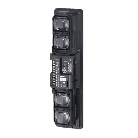
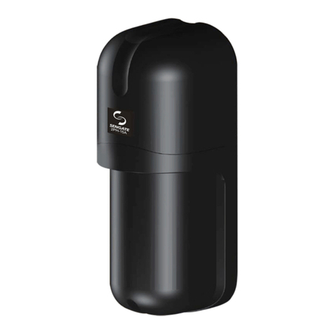
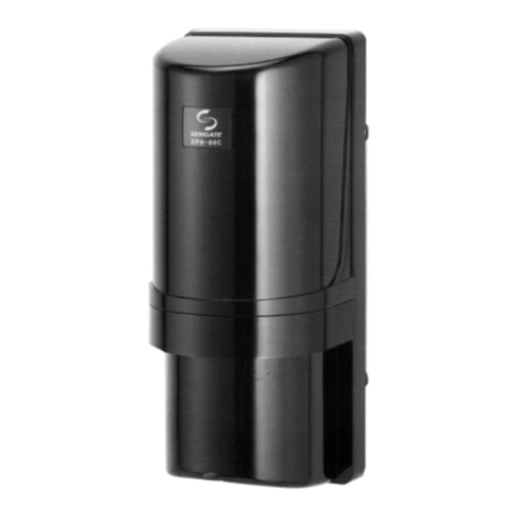
Sengate PH-15FA User manual

1
PH-15FA / PH-15SA
80~100 cm
HEIGHT
Base Unit
Wiring
Front Cover
Vertical Adjustment
Len
Horizontal Adjustment
Screws
Front Cover
Base Unit
Horizontal Adjustment
Vertical Adjustment
Len
Tamper Switch
Terminals
Wiring Hole
Attenuation Sheet
5/32"x1 "
(4x25 mm)
Screws
4.9ft
1.5M
50ft
(15M)
)(
Thanks for purchasing this product. Read this instruction before using the product to make sure that you use it correctly.
1
PH-15FA
(FLUSH Mount)
PH-15SA
(SURFACE Mount)
2
PARTS NAME:
15M SINGLE PHOTOELECTRIC BEAM SENSOR
● ●
● ●
FEATURES OF THE PRODUCT
DRIP-BREAKER DESIGN, PH-15FA COULD BE FOR OUTDOOR/INDOOR.
FLUSH AND SURFACE MOUNT FOR OPTIONS.
3-STEP LED INDICATOR FOR EFFECITVE ALIGNMENT.
BUILD WITH HIGH GRADE ASPHERIC LENS.
MANUAL INSTRUCTION
IMPROPER LOCATION
DETECTION RANGE
INSTALLATION HEIGHT
Avoid any possible objects between
Transmitter and Receiver ( ex. Curtain, Bonsai …. )
Avoid direct sunshine and long-time strong sunshine,
that would hurt product's life.
With 15M Detection Range between
Transmitter and Receiver.
PRECAUTIONS FOR INSTALLATION:
As these products are designed to detect humans, installing
so that the center of the sensors are at a height of approximately
80cm~100cm from the ground for both wall and pole mounting.

2
4
6 741 32 5
COM
_
+NC.
NO.
NC.
}
}
1223
1412
1234
}
}
}
1212
34
12
23
14
(PH-15FA)
(PH-15FA)
(PH-15SA)
(PH-15SA)
+_
1 2
+_
COM
_
+
NO.
NC.
PH-15FA
(FLUSH Mount)
PH-15FA
(FLUSH Mount)
PH-15SA
(SURFACE Mount)
PH-15SA
(SURFACE Mount)
3
<Transmitter>
<Transmitter>
Transmitter
Transmitter
Transmitter
Transmitter
<Receiver>
<Receiver>
Receiver
Receiver
Receiver
Receiver
Connect Example (A)
Connect Example (B)
Red Black Yellow Green BlueRed Black
Power
Power
Alarm Signal 1
Alarm Signal 1
Alarm Signal 2
Control Panel
Control Panel
(The length spec between wiring and sensors)
NOTE:
1. When two(2) or more units are connected, the wiring distance is calculated
as above,the figure on the left divided by number of units.
2. The main wires for power couldn't exceed above-mentioned length.
3. Signal wiring connection should consider the possible impedance matching
from the wiring of Control Panel.(ex.Terminal Resistor)
PH-15FA / PH-15SA
12VDC 24VDC
MODEL
VOLTAGE
WIRE
300 M
AWG22 (0.65mm) 2000 M
800 M
AWG18 (0.80mm) 5000 M
550 M
AWG20 (0.80mm) 3300 M
1000 M
AWG17 (1.10mm) 6000 M
WIRING:
INSTALLATION PROCEDURE:
ADJUSTMENT ANGLE
WIRING
LENGTH OF THE WIRING
POWER AND SIGNAL INSTALLATION
Screw for Vertical Adjustment
Clockwise : Downward
Counterclockwise : Upward
Screw for Vertical Adjustment
Clockwise : Downward
Counterclockwise : Upward
Horizontal ±15°
Vertical ±5°
Horizontal ±90°
Vertical ±5°
Power
DC10.5V~28V
(Non-Polarity)
Power
DC10.5V~28V
(Non-Polarity)
Power
DC10.5V~28V
(Non-Polarity)
Power
DC10.5V~28V
(Non-Polarity)
Alarm Output
Dry Connect Relay
NC./NO. 0.2A/30VDC
Alarm Output
Dry Connect Relay
NC./NO. 0.2A/30VDC
Tamper Output
Dry Connect Relay
NC. 0.2A/30VDC
PH-15FA (BOX MOUNTING)
4-1-1 Remove the cover piece with screwdriver.
4-1-2 Refer to section [ 3.WIRING ] to connect the wiring.
4-1-3 Organize the wirings into the box and fix with screws .
4-1-4 Refer to section [ 5. ALIGNMENT ] and check if alignment done
properly, if yes, then attach the cover piece back.
5/32"x1"

3
Receiver LED Operation
Red/Yellow LED Off
Yellow LED lit
( Red LED Off )
Red
Yellow
LED lit
( LED Off )
Receiver Condition
Strong ( operation well )
( re-adjust, no Alarm Output )
Weak
Alarm Output
2.5mm
3.29"(83.5mm)
5
Vertical adjustment Vertical adjustment
Horizontal adjustment
Attenuation sheet
Horizontal adjustment
Attenuation sheet
This function informs you of the operation and
condition of the receiver by LED.
PH-15SA
(Surface Mounting)
attached paper pattern
4-2-1 Remove the cover piece
with screwdriver.
4-2-2 Use attached paper pattern
to cut hole on the wall.
4-4-1 Remove the cover piece with
screwdriver.
4-4-2 Install the screw in switch
box and keep 2.5 mm space
between as the drawing.
5/32"x1"
4-4-3 Put the infrared beam unit in switch
box (Drawing-1), and fix the screw
tightly (Drawing-2).
4-4-4 Refer to section [ 3. WIRING ] to
connect the wiring.
PH-15FA ( WALL MOUNTING )
PH-15SA ( WALL MOUNTING )
PH-15SA ( BOX MOUNTING )
4-2-3 According to the position identified
to drill two(2) fixing holes(2 mm).
4-2-4 Refer to section [ 3. WIRING ] to
connect the wiring.
4-2-5 Install and fix screws
4-2-6 Refer to section [ 5. ALIGNMENT ] and
check if alignment done properly, if yes,
then attach the cover piece back.
5/32"x1" .
4-3-3
4-3-4 Refer to section [ 5. ALIGNMENT ] and check if alignment
done properly, if yes, then attach the cover piece back.
Refer to section [ 3. WIRING ] to connect the wiring.
4-3-1 Remove the cover piece with screwdriver.
4-3-2 Pull wiring thru cable entry and fix the unit on
with screws
the wall
5/32"x1" .
4-4-5 Refer to section [ 5. ALIGNMENT ] and
check if alignment done properly, if yes,
then attach the cover piece back.
OPTICAL ALIGNMENT PROCEDURE:
5-1 Turn on the power to the PH-15FA/SA Transmitter and Receiver.
5-2 Adjust Transmitter and Receiver vertically and horizontally to do
axis adjustment.
5-3 Check Receiver LED Operation, adjust Transmitter and Receiver
horizontally again till Receiver LED is off.
5-4 Put the Attenuation sheet in front of the Receiver to weak the signal,
then repeat the section [5-3] till Receiver LED is totally off.
This procedure could make sure Receiver got better and steady operation.
optical
vertically and
PH-15FA
(Flush Mounting)
①
②

4
Web Site : http://www.sengate.com
E-Mail : service @ sengate.com
Designing / Manufacturing
Taiwan Security Net Co., Ltd. Designing / Manufacturing
Taiwan Security Net Co., Ltd.
No.4-46, Fengren Rd., Renwu Dist., Kaohsiung City 814, Taiwan
TEL 886-7-3721111~4 FAX 886-7-3728650 : :
No:A059B02-01
Unit : (inch mm)
2.22 56.5)" (
4.13 (104.85)"
3.31 84.0)" (
2.78 70.6)" (
5.14 130.6)" (
1.79 (45.6)"
2.76 (70.0)"
4.72 120.0)" (
3.29 83.5)" (
2.95 75.0)" (
1.73 44.0)" (
1.14 29.0)" (
PH-15FA (FLUSH Mount)
PH-15SA (SURFACE Mount)
PH-15FA PH-15SA
150ms (100~200ms)
-25℃ ~ +55℃
2.76"x 4.72"x 1.73"
(70.0x120.0x44.0 mm)
2.78"x 5.14"x 2.22"
(70.6x130.6x56.5 mm)
Indoor / Surface Mount
6
TROUBLE-SHOOTING GUIDE:
7 8 DIMENSIONS:SPECIFICATION:
CONDITION POSSIBLE CAUSE REMEDY
Operation LED doesn’t light.
(Transmitter)
Receiver
when
Alarm LED does not light
the beam is broken.
Receiver Alarm LED Alarm stays lit.
1. Disruption of power or inadequate power.
2. Bad wiring connection or broken wire, short.
1. Correct Power source.
2. Check and correct wiring.
1. Disruption of power or inadequate power.
2. Bad wiring connection or broken wire, short.
3. Reflection of beam is flooding receiver and sent into
the receiver.
1. Correct Power source.
2. Check and correct wiring.
3. Remove reflecting object or change the
installation location.
1. Bad wiring Connection.
2. Unstable power source.
3. Shading object between Transmitter and Receiver.
4. The wiring of power machine is located nearby
Transmitter and Receiver.
5. Unstable installation of Transmitter and Receiver.
6. Optics of units are soiled.
7. Improper alignment.
1. Check and correct wiring.
2. Stabilize supply voltage.
3. Check and remove any possible obstacles.
4. Change environments or place for installation to
avoid the interference source.
5. Looking for proper installation location.
6. Clean the optics with soft cloth.
7. Check and re-adjust.
Intermittent Alarm.
1. Alignment is off.
2. Shading object between Transmitter and Receiver.
3. Optics of units are soiled.
1. Check and adjust.
2. Check and remove any possible obstacles.
3. Clean the optics with a soft cloth.
MODEL NO.
Supply Voltage
Standard Accessories
Environment Humidity
Ambient Temperature
Detection System
Response Time
Interruption Time
Alarm Output
Tamper Output
Indicator LED
Functions
Wiring
Beam Adjustment
Mounting Position
Weight
Dimension (W X H X D)
Transmitter:Green Operation LED lights on when
with power on.
cover is
opened
Receiver:Red Alarm LED lights on when an alarm is initiated.
Yellow Sensitive LED lights on when beam reception
is attenuated.
Both Yellow and Red LED should be off as correct
installation.
Horizontal Vertical ± 90° ± 5°
Please Note:
1.This sensor is designed to detect intrusion and initiate an alarm; it is not a burglary-preventing device.
2.We are not responsible for damage, injury or losses caused by accident, theft,
misuse, abnormal usage, faulty installation or improper maintenance.
3.Specifications and design are subject to change without prior notice.
Acts of God (including inductive surge by lightning), abuse,
6.9oz (195g) 9.7oz (275g)
Indoor / Outdoor / Flush Mount
Screw 5/32" x 1
Attenuation sheet X 1 pc
" X 4 pcs
Horizontal Vertical ± 15° ± 5°
AWG26 Wiring Terminals
95% (Max.)
3- step Alignment LED.
Dry Contact NC. 0.2A/30VDC
None
Dry contact relay NC. / NO. 0.2A / 30VDC
(When the beam is blocked.)
1second
Pulsed Infrared 1000pps
Infrared beam interruption system
10.5V~28VCD (Non-Polarity)
Transmitter 12mA (16mA Max.)
Receiver 24mA (26mA Max.)
150 M
Indoor 15 M
Detection Range
Tenfold Distance
Beam Characteristics
Current Consumption
This manual suits for next models
1
Other Sengate Accessories manuals


