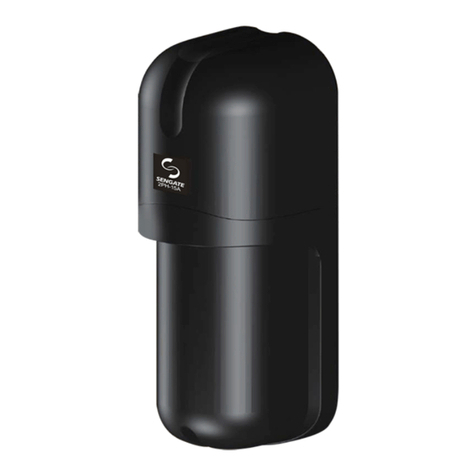
Sengate 2PH-30C User manual

1
Monitor + Monitor -
90
5
Please read this instruction Manual carefully for correct and effective use. If you do not
understand these instructions, contact your supplier for further information.
2PH- 30C Outdoor 90ft. (30m) / Indoor 180ft. (60m)
2PH- 60C Outdoor 180ft. (60m) / Indoor 360ft. (120m )
This sensor is designed to detect intrusion and to activate an alarm. It only provides an alarm
sign output, and is not an independent burglar-preventing device. If it's used abnormally,
faulty installation, improper maintenance or Acts of God, it will cause damage.
NOTE
Response Time Adjustment
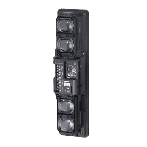
LED Indicator
( Transmitter Only )
Horizontal
Adjustment
Terminals
Alarm LED
Lens
Tamper Switch
View Finder
Vertical
Adjustment Screw
Unit Base Mounting Plate
Screws U_Shaped
Brackets
Attenuation SheetCover
Detection Range
Detection Width L A
60' (20m) 1.8' (0.6m)
120' (40m) 3.6' (1.2m)
180' (60m) 5.4' (1.8m)
Wrong place
Remove all obstructions ( trees,
clothes lines, etc.) between
Transmitter and Receiver.
Do not install the unit on places
where it may be splashed by
dirty water or direct sea spray.
Do not install the unit on the unsteady
place.
Avoid strong light from the sun, headlights,
and direct shining on the Transmitter /
Receiver.
When strong light stays in optical axis for
a long time, it will hurt the product's life.
Please make the Transmitter and Receiver within the required range as
belows :
2PH-30C Outdoor 90ft. (30m) / Indoor 180ft. (60m)
2PH-60C Outdoor 180ft. (60m) / Indoor 360ft. (120m )
The detection width can be calculated
with following formula :
Width A = 0.03 x Length (L)
Transmitter Receiver
L
Protection distance
A
Installation Height Alignment Angle
The sensors can be adjusted with
Horizontal ±90° and Vertical ±5°
to fit big detection range.
To detect the intruder efficiently,
the sensors should be installed
within 32"-40" (80-100 cm)
height.
( Receiver Only ) ( Receiver Only )
( Receiver Only )
( Receiver Only )
30M/60M TWIN PHOTOELECTRIC BEAM SENSOR
(80~100cm)
32"~40"
PARTS DESCRIPTION:
1
CAUTIONS ON INSTALLATION:
2

1 2 34567
COM
NC.
NO.
NC.
AWG22 (0.65mm)
AWG20 (0.8mm)
AWG18 (1.0mm)
AWG17 (1.1mm)
2PH-30C 2PH-60C
24VDC24VDC 12VDC12VDC
+_
+_
1 2
}
}
}
}
}
1 2 3 4
1 2 1 2 3 4 1 2 1 23 4
1 2 1 2 3 4 1 2 1 23 4
Receiver
Wiring Distance
Power
10V to 30VDC (non-polarity)
10V to 30VDC
(non-polarity)
Alarm output
Dry connect relay
output NC. /NO.
28V DC. 0.2A
Tamper output
Dry connect Micro.SW.
output NC.
28V DC. 0.2A
960
( 320m )
'8400
( 2800m )
'840
( 280m )
'7200
( 2400m )
'
1650
( 550m )
'14400
( 4800m )
'1350
( 450m )
'12600
( 4200m )
'
2400
( 800m )
'21600
( 7200m )
'2100
( 700m )
'18600
( 6200m )
'
2940
( 980m )
'26400
( 8800m )
'2550
( 850m )
'22800
( 7600m )
'
Voltage
Wire size
Model
NOTE : 1.When two or more connections is required, maximum wiring
distance is the value above divided by the number of sets.
2.The power wires could not exceed the above mentioned
lengths.
Signal
Transmitter Receiver
Control panel
Power
Alarm
Signal
Control panel
Power
TR. RE.
Alarm (1ch.)
Alarm (2ch.)
TR. RE. TR.RE.
Connection Sample 2
Connection Sample 3
The units can be mounted easily on a pole or flat surface.
Remove cover via screw at base of cover. And loosen the unit base
mounting screw and remove mounting plate by sliding it down against
the unit base.
A.WallMounting
Pull out the wire through the wiring hole on the mounting plate
and attach the plate to the wall with the screw ( 1/6" x 3/4" )
A-1. A-3.
After checking optical alignment and operation check, (Pleasesee5.
ALIGNMENTANDOPERATION)replace the cover, and fasten the
cover lock screw tightly.
A-2. Connect wire to the terminals.
TR.RE.
INSTALLATION:
4
12
}
}
Transmitter Connection
Control panel
Power
Alarm
Connection Sample 1
WIRING:
3
2

3
0.70.05
50ms 100ms 300ms 500ms 700ms
B.PoleMounting
Unit mounts to a 1.66"-1.75" O.D. pole.
Drill a 1/4" hole through pole where the beam will be mounted
for wiring.
B-1.
B-2.
B-3.
B-4.
B-5.
B-6.
B-7.
Place U-Shape brackets at the pole.
Pull out the wire through the wire through the wiring hole of the mounting
plate, attached the mounting plate to the U-Shape bracket with screw.
Connect the wire to the terminals.
Checking optical alignment and operation check.(Please see 5.
ALIGNMENT AND OPERATION)
Replace the cover, and fasten the cover lock screw tightly.
C.TwoUnitsinstallation(BacktoBack)
Fix two U_
Shape brackets in layers on a pole, two units can be installed
back to back on a pole at the same height.
5-1. Apply power to both Transmitter and Receiver.
5-2. Looking through the view finder, locate the other detector in the center
of the sights by adjusting vertically and horizontally.
View Finder
Vertical adjustment screw
Screw clockwiseUpward
CounterclockwiseDownward
:
:
Rough Horizontal Adjustment
5-3. Connect the volt-meter (DC10V) to monitor jack input on Receiver's (+)
and (_ ), then fine tune optical alignment.
5-4. Fine adjust the optical alignment for Transmitter to obtain the maximum
voltage from the monitor jack.
5-5. Fine adjust the optical alignment for Receiver to obtain the maximum
voltage from the monitor jack.
5-6. Place attenuation sheet on Receiver lens repeating 5-4 & 5- 5 to obtain
the maximum voltage from the monitor jack.
SENSITIVITY CHART
Monitor Jack Output Alignment Level
Best
4 V Over
3V to 4 V Good
3V Under Poor, Realign
NOTE:
(1) Above readings is under attenuation sheet operation.
(2) Carefully remove the attenuation sheet, and check the voltage from the
monitor jack again.
Monitor Jack (+)
Attenuation Sheet
OPERATIONCHECK
Monthly check is required, test operation by walk testing the beam.
:
The beam interruption time adjustment is on Receiver unit. Speeds shown below
are the maximum detectable speeds for each setting.
NOTE: After installation, response time testing is required. This function allows you to match the units sensitivity to its surroundings.
Response time (sec.)
Fast running Jogging speed Normal walking Slow speed Jumping cat
Receiver
Monitor Jack (-)
RESPONSE TIME ADJUSTMENT:
6
ALIGNMENT AND OPERATION:
5

4
Web Site : http : // www.sengate.com
E-mail : service @ sengate.com
No.4-46, Fengren Rd., Renwu Dist., Kaohsiung City 81459, Taiwan (R.OC)
TEL : +886-7-3721111~6 FAX: +886-7-3728650
2PH - 30C 2PH - 60C
NOTE:
1. This unit is designed to detect an intruder and activate an alarm control panel.
Being only a part of complete system, we cannot assume responsibility for theft
or damages, should it occur.
2. Specifications and design are subject to change without prior notice.
Red LED ( Receiver ) lights when an alarm is initiated.
Monitor jack output, AGC circuit, Frost proof cover.
W3" x H7.1" x D3.1" ( W76 x H181.5 x D77.8 )
Outdoor 90ft. (30m)
Indoor 180 ft. (60m)
Outdoor 180 ft. (60m)
Indoor 360 ft. (120m )
MODEL
Detection Distance
Max. Arrival Distance 9000 ft.(300m) 1800 ft.(600m)
Current Consumption 36mA ( max ) 42mA ( max )
Power Supply 10V ~ 30VDC ( Non-Polarity )
Detection System Infrared Photoelectric
Response Time 50msec ~ 700msec ( Adjustable )
Alarm Output Contact action: 0.5 sec. To 2 sec.
Tamper Output Dry connect relay NC. 0.2A / 28VDC
( NC. opens when cover is removed. )
Alarm LED
Functions
Alignment Angle Horizontal 90, Vertical 5±°
±
°
Operating Temperature
_13F to +131F (
_25C to +55C )
°° ° °
Mounting Positions Indoor / Outdoor
Wiring Terminals
Weight
32.7oz(925g) Transmitter & Receiver
;
Dimensions(inches
/
mm)
Standard Accessories
U_
Shaped brackets x 2
Attenuation Sheet x 1
Screws ( 4 x 20 Self tapping ) x 4
Screws ( M4 x 20 ) x 4
Unit:inch (mm)
Dry connect relay NC./ NO. 0.2A / 28VDC
Corrective Action
Operation LED does not light.
( Transmitter Unit )
1. No power supply.
2. Bad wiring connection or broken wire, short.
1. Turn on the power.
2. Checking wiring.
Alarm LED does not light
when the beam is broken.
( Receiver Unit )
1. No power supply.
2. Bad wiring connection or broken wire, short.
3. Beam is reflected on another object and sent into the
receiver.
4. Two beams are not broken simultaneously.
5. The beam interruption time is shorter than the set
response time.
1. Turn on the power supply.
2. Check wiring.
3. Remove the reflecting object or change
beam direction.
4. Break two beams simultaneously.
5. Set the response time shorter.
Alarm LED continues to light.
( Receiver Unit )
1. Beam alignment is out.
2. Shading object between Transmitter and Receiver.
3. Optics of units are soiled.
1. Check and adjust again.
2. Remove the shading object.
3. Clean the optics with a soft cloth.
Intermittent alarms 1. Bad wiring connection.
2. Change of supply voltage.
3. Shading object between Transmitter and Receiver.
4. A large electric noise source, such as power machine,
is located nearby Transmitter and Receiver.
5. Unstable installation of Transmitter and Receiver.
6. Soiled optics of Transmitter and Receiver.
7. Improper alignment.
8. Small animals may pass through the 2 beams.
1. Check again.
2. Stabilize supply voltage.
3. Remove the shading object.
4. Change the place for installation.
5. Stablize.
6. Clean the optics with a soft cloth.
7. Check and adjust again.
8. Set the response time longer. ( Impossible in a
site where an intruder can run at full speed. )
No:A020B01-01
Trouble Check
TROUBLE SHOOTING:
7
SPECIFICATIONS:
8
DIMENSIONS:
9
3"(76)
7.1"(181.5)
1.9"(48)
1.2"(30)
3.3"(83.5)
2.7"(69.3)
1.5"(37.8)
3.1"(77.8)
This manual suits for next models
1
Other Sengate Accessories manuals
Popular Accessories manuals by other brands
I-note
I-note Mobile Note Taker Pro user guide

Trotec
Trotec PV4-MID-PS operating manual

ADEMCO
ADEMCO Quest 2235 installation instructions
Balluff
Balluff BML-S1G0 7 M5E 0 Series Condensed guide

Lovibond
Lovibond DI 10 quick start guide
PCB Piezotronics
PCB Piezotronics ICP 209C02 Installation and operating manual
