Senmatic InClimate User manual
Billede nr. 2
InClimate - Installation and mounting instructions
InClimate is used as stand-alone transmitter or via Modbus to CTS, for measurement of room
temperature, CO and relative humidity.2
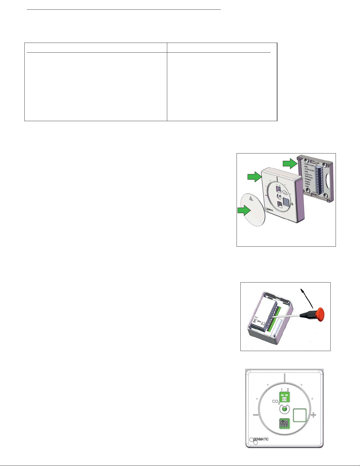
InClimate consists of a mounting base, a scale button and a
controller/transmitter: ( )See image no. 1
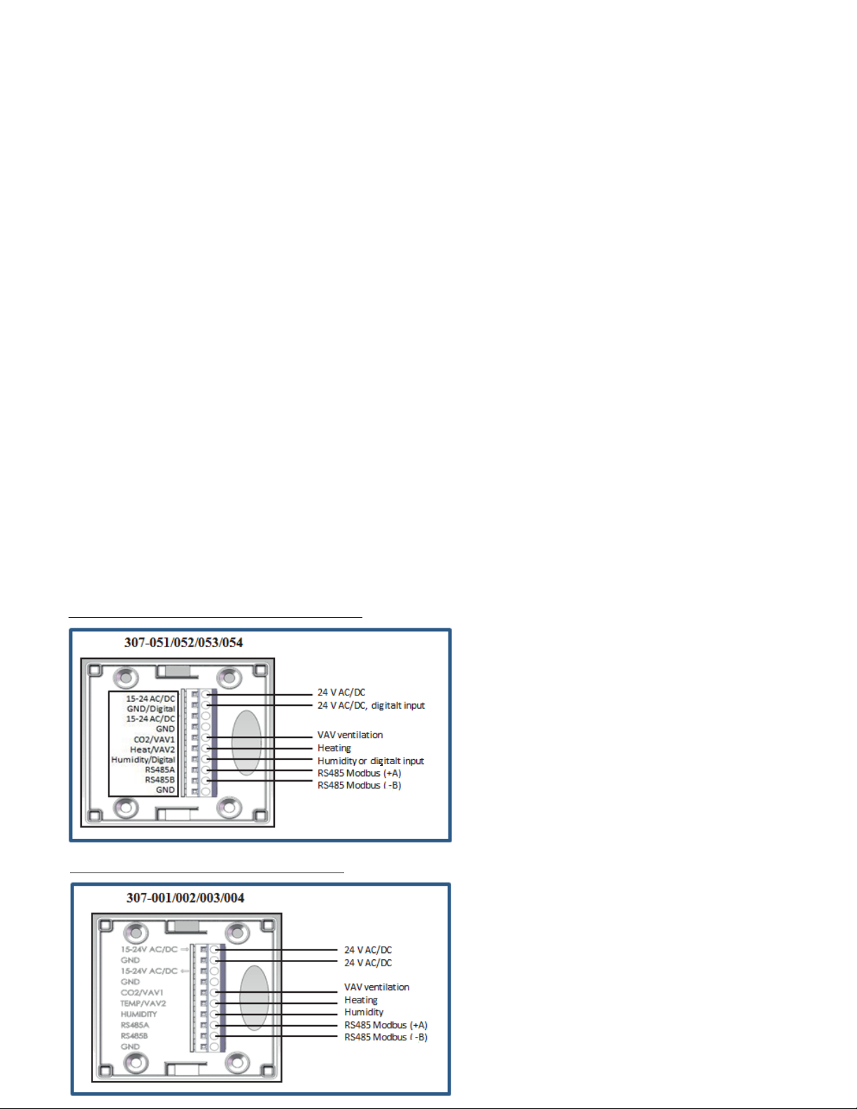
1. Scale button is dismounted as shown in image 2 using a
screwdriver max. 4 mm.
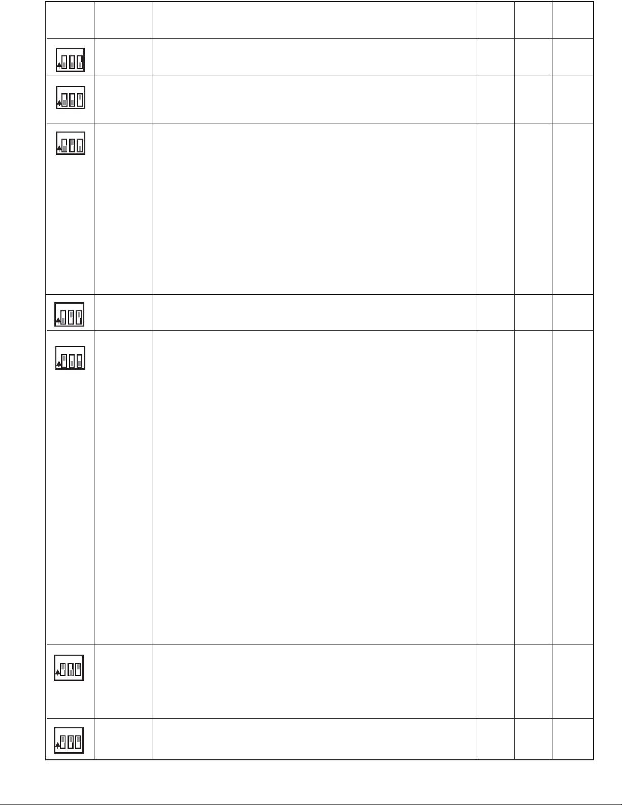
2. Controller/transmitter features a CO2 potentiometer and a
DIP switch for setting of Mode under the temperature scale
button.(see image no. 3).
3. Monting base includes 10 pcs 1.5 mm² terminal screws.
Installation:
Installation of InClimate should only be done by qualified
persons. The thermostat is placed on an even wall min. 150 cm
above the floor. Avoid draught and thermal radiation. Do not
place in niches or in bookcases or behind curtains, above or
close to heat sources. Do not expose to direct sun radiation.
3
2
1
Billede nr. 1
Billede nr. 3
Description (*) Item number
Temp-CO2-RH-(Digital input) 307-051
Temp-CO2-(Digital input) 307-052
Temp-RH-(Digital input) 307-053
Temp-(Digital input) 307-054
(*) 2 x 0-10 V outputs and 1 digital input
Programming tool 307-009
Description (**) Item number
Temp-CO -RH 307-0012
Temp-CO 307-0022
Temp-RH 307-003
Temp 307-004
(**) 3 x 0-10 V outputs.
Bl 307-007ind cover
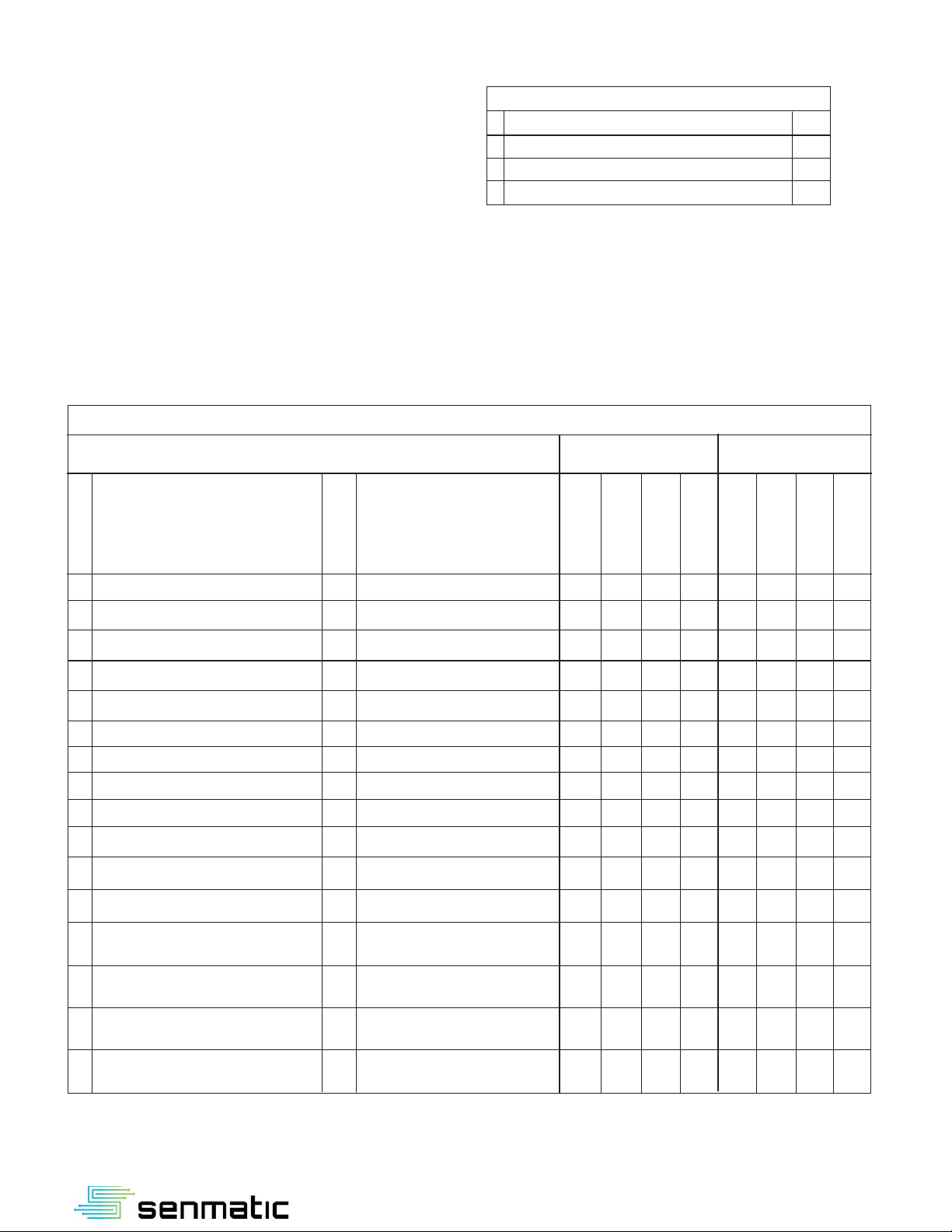
Connection of cable:
Cables can be connected from the back or the top or the bottom
via knockout blanks.
Description of function (see Description of mode, page 2):
1. Select function/mode
2. Temperature adjustment:
The required temperature is adjusted on the scale button.
3. CO2 adjustment (factory adjustment 800 ppm):
The required CO2 is adjusted by turning the inside
potentiometer. (See image 2).
4. Humidity:
The value is read off. The set point is not adjustable or
readable. Is only used in connection with BMS-systems.
InClimate has 2 LED light diodes which indicate the current
status of the temperature and CO2 value (Image no. 3):
1. LED1 lights, if the room temperature is higher than the set
point.
2. CO2
LED2 lights, if the content of is higher than the set-point.
Both LEDs are automatically switched off after 5 minutes.
When changing the set-points, the LEDs are activated..
Teknisk information:
Operating voltage: 24V AC / DC
Power consumption: 1.0 W
Dimenstions: 80 x 80 x 23 mm
IP-class (EN60529): IP 54
Colour: White (RAL 9010)
Installation: Wall-mounted
Weight: 85 g
Certification: CE
Bus communication: RS485/Modbus RTU, Data (+A), (-B)
Temperature measurement:
Measuring range: 0°C - 50°C
Set-point function: 5°C – 30°C (fully scalable)
Accuracy: <+/- 1°C of full scale
Linear output: 0-10 V min. load 10kΩ (Image no. 3)
CO2 measurement:
Measuring range: 0-2000 ppm
Set-point function: 600 – 1200 ppm (fully scalable)
Accuracy: 50 ppm ved 20°C, ABC self-calibrating
Linear output: 0-10 V min. load 10kΩ
Relative humidity measurement:
Measuring range: 0-100% RH
Accuracy: +/-5% RH (20% - 95%)
Linear output: 0-10 V min. load 10kΩ (**)
Digital input:
Programmable for: PIR sensor, window relay or extended operation
Connection diagram - digital input:
Connection diagram 3x10V output:
O
N
123
O
N
123
O
N
123
O
N
1
23
O
N
123
O
N
123
Mode
Switch
Pos.
Mode
description
CO2
VAV1
0-10V
Temp
VAV2
0-10V
Humi-
dity
0-10V
Transmitter-
mode
0
a. No adjustment options for temperature, CO2 and RH.
Pure transmitter-mode.
CO2
0-2000
PPM
Temp.
0-50°C
Humidity
0-100%
Only 307-
001/003
Transmitter
mode with
setup function.
a. No adjustment options for temperature and CO2.
Pure transmitter-mode.
b. Scale button can be used for the setup function
0-10V is read off Humidity/VAV3., only applies for 307-001/003
Temp.
0-50°C
Setup
function
only 307-
001/002/
003/004
1
2a. Fixed set point of 21 °C. The temperature can be adjusted +/- 3 °C.
b. CO2 is adjustable from 600 to 1200 ppm on the internal potentiometer.
Standard setting 800 PPM
c. Options for VAV1 control parameter:
0=Vout1 (standard) is controlled through CO and temperature, the highest
calculated PI value is deciding.
1=Vout 1 is controlled solely through temperature. CO2 set point is ignored.
2= Vout1 is controlled solely through CO2. Temperature set point is ignored.
d. VAV1 minimum voltage 0 to 10V for ventilation damper is possible.
0=Standard 0V, 20=2V, 55=5,5V, etc.
e. Options of window functionality:
The window function works by means of the sensor constantly checking the
temperature change over a period of 5 minutes. If for example the temperature has
dropped more than five degrees during this period, the sensor will shut off the heat
(VAV2). The heat will be turned off for 20 minutes. The desired temperature change
can be set, standard 5°C.
f. Possibility of choosing dead zone functionality:
Standard 0°C, can be activated and changed up to ±10 °C.
Standalone
Three PI
regulators
control VAV1
and VAV2.
There are PI
parameters
for CO2 and
temperature
for VAV1 and
there are PI
parameters
for VAV2
temperature
for the heat
valve
adjustment.
3Stand-alone
PI-adjustment
See mode 2.
a. The temperature can be adjusted between 5 °C and 30 °C.
Other setting options – see mode 2.
4Modbus
(Also as
Stand-alone)
Data is sent
to the BMS
terminal
a. Possible to choose digital input etc. Standard setting is ”0” for register 40003 = AC.
See program guide page 4
b. Standard fixed set-point is 21°C. The temperature is adjustable ±3°C.
Set-point (temp og CO2) can be local or be changed by Modbus or Local
Temperature set-point and CO2 via Modbus. 0=Standard local, 1=via Modbus,
2 Local Temperature set-point and CO2 set-point via Modbus.
c. Possibility of adjustment of centre point and ± span on the temperature potentio-
meter. Standard 21°C, +/-3°C.
d. Lokal PI regulator.
PI regulators control VAV1 and VAV2. There are PI parameters for CO2 and
temperature for VAV1, and PI parameters for VAV2 temperature for the heat valve
r.egulation
e. Options for choice of VAV1 control-parameters:
0=Vout1 (standard) is controlled through CO2 and temperature, where the highest
calculated PI-value is deciding.
1=Vout1 is controlled solely through temperature. CO2 set-point is ignored.
2=Vout 1 is controlled solely through CO2 Temperature set-point is ignored.
.
f. VAV minimum voltage 0 to 10V for ventilation damper.
0=Standard 0V, 20=2V, 55=5,5V, etc.
g. Forced opening of VAV1:
0=Standard, 1=Forced opening of VAV1 in Unoccupied mode.
h. Optional choice of window function:
The window function works through the sensor constantly checking the
temperature change over a period of 5 minutes. If for example the temperature has
dropped more than five degrees during this period, the sensor will shut off the heat.
(VAV2). The heat will be turned off for 20 minutes.
The required temperature change can be set, standard 5°C.
i. Optional choice of 3 full dead zone functionalities:
0=Occupied, standard ±1 °C.
1=Standby, standard ±3 °C.
2=Unoccupied, standard ±6°C, possibility of forced opening of VAV1 damper.
j. Possibility of choosing downdraft function:
Possibility of opening the VAV2 heat valve percentage-wise depending on the
outdoor temperature.
5Modbus is
controlled
from the BMS
system only.
Humidity
output only
applicable for
307-001
a. Possibility of choosing digital input etc. Standard setting is ”0” for register 40003 =
AC. See program guide page 3
b. No adjustment options for temperature, RH and CO2.
All sensor values are read via Modbus and output voltages from InClimate are
BMScontrolled from central unit.
CO2
0-2000
PPM
VAV
control
Temp.
control
No
output
VAV
control
Temp.
control
No
control
VAV
control
Temp.
control
No
control
Controlled
from
CTS
O
N
123
7Forced
control
a. Forced opening (VAV1, VAV2, VAV3) 10V
cannot be used for withVAV3, InClimate digital input. VAV1 VAV2 VAV3
InClimate functions and various functions are changed via Modbus
or InClimate programming tool (ordering number 307-009)
Humidity
output
Only 307-
01/002/
003/004
Controlled
from
CTS
Digital input
Selection guide for digital input in register 40004
Digital input, choise of below options:
1. Extended operation
(normally open or normally closed switch)
2. Pir Sensor or window relay
(normally open or normally closed switch)
InClimate selection guide in register 40003
Following set-up options are available in register 40003:
1. AC or DC (Default ”0” = AC)
2. CO2
3. RH
4. Digital input
5. Blind cover, temperature offset for blind cover to be done according to the mounting
instructions for blind cover in register 40035.
0 AC (standard) 100 DC X
1 AC + CO2 101 DC + CO2 X
2 AC + CO2 + RH 102 DC + CO2 + RH X
3 AC + RH 103 DC + RH X
4 AC + Digital input 104 DC + Digital input X
5 AC + CO2 + Digital input 105 DC + CO2 + Digital input X
6 AC + CO2 + RH + Digital input 106 + + + XDC CO2 RH Digital input
7 AC + RH + Digital input 107 DC + RH + Digital input X
8 AC + blind cover 108 DC + blind cover X
9 AC + CO2 + blind cover 109 DC + CO2 + blind cover X
10 AC + CO2 + RH + blind cover 110 DC + CO2 + RH + blind cover X
11 AC + RH + blind cover 111 DC + RH + blind cover X
12 AC + Digital input + 112 DC + Digital input +
blind cover blind cover X
13 AC + CO2 + Digital input + 113 +DC + CO2 Digital input +
blind cover blind cover X
14 AC + CO2 + RH + Digital input + 114 DC + CO2 + RH +
blind cover Digital input + blind cover X
15 AC + RH + Digital input + 115 DC + RH +
blind cover blind cover XDigital input +
Item
Value
307-051
Temp-Co2-RH
Description Description
Parameter With digital input Without digital input
description with 2 x 0-10V with 3 x 0-10V
InClimate selection guide in register 40003
307-052
Temp-Co2
307-053
Temp-RH
307-054
Temp
307-001
Temp-Co2-RH
307-002
Temp-Co2
307-003
Temp-RH
307-004
Temp
103-995_V3.0
For further information: www.senmatic.dk/sensorer/inclimate
Senmatic A/S
Industrivej 8 - DK-5471 Søndersø
Register 40004 - Selection guide digital input table
0 Operation switch NO
1 Operation switch NC
2 Pir sensor / window relay NO
3 Pir sensor / window relay NC
Popular Transmitter manuals by other brands

Comnet
Comnet FVT80D8SFP Installation and operation manual

Waio
Waio AXS-FMTD manual

Siemens
Siemens SITRANS P500 Compact operating instructions

Kurz Instruments, Inc
Kurz Instruments, Inc 454FT-08-MT user guide

HumanTechnik
HumanTechnik lisa Operation instructions

Tele Radio
Tele Radio T19-02 User instructions

Audiovox
Audiovox PurSuit 091BPr Programming guide

HK Instruments
HK Instruments DPT-Flow-1000 Installation instructions and owner's manual

RKI Instruments
RKI Instruments 65-2649RK-HC-04 Operator's manual

AMC
AMC CM800-Mini Installer manual

IFM
IFM efector600 TAD 61 Series operating instructions

Vibradorm
Vibradorm VFF/DB-Basic operating instructions


