IFM efector600 TAD 61 Series User manual

Operating instructions
Long-term stable, self-monitoring
temperature transmitter
TADx61
706044/00 06/2006
UK

2
Contents
1 Preliminary note���������������������������������������������������������������������������������������������������3
1�1 Symbols used ������������������������������������������������������������������������������������������������3
2 Safety instructions �����������������������������������������������������������������������������������������������3
3 Functions and features ����������������������������������������������������������������������������������������3
3�1 Application �����������������������������������������������������������������������������������������������������3
4 Function���������������������������������������������������������������������������������������������������������������4
4�1 Monitoring and diagnostic functions ��������������������������������������������������������������4
4�1�1 Drift / fault monitoring ��������������������������������������������������������������������������4
4�1�2 Sensor backup / redundancy switching ������������������������������������������������5
4�1�3 Response of the outputs in case of a fault �������������������������������������������5
4�2 Analogue function ������������������������������������������������������������������������������������������7
5 Installation������������������������������������������������������������������������������������������������������������8
6 Electrical connection������������������������������������������������������������������������������������������10
7 Parameter setting ����������������������������������������������������������������������������������������������10
7�1 Adjustable parameters���������������������������������������������������������������������������������10
7�2 Service functions �����������������������������������������������������������������������������������������13
8 Operation�����������������������������������������������������������������������������������������������������������13
8�1 Fault indication ��������������������������������������������������������������������������������������������13
9 Scale drawing ����������������������������������������������������������������������������������������������������15
10 Technical data��������������������������������������������������������������������������������������������������16
10�1 Temperature resistance �����������������������������������������������������������������������������17
11 Factory setting �������������������������������������������������������������������������������������������������17

3
UK
1 Preliminary note
1.1 Symbols used
►Instruction
> Reaction, result
[…] Designation of pushbuttons, buttons or indications
→Cross-reference
Important note
Non-compliance can result in malfunctions or interference�
2 Safety instructions
• Please read this document prior to set-up of the unit� Ensure that the product is
suitable for your application without any restrictions�
• If the operating instructions or the technical data are not adhered to, personal
injury and/or damage to property can occur�
• Checkthecompatibilityoftheproductmaterials(→chapter10Technicaldata)
with the media to be monitored in all applications�
3 Functions and features
The unit detects the system temperature in installations�
3.1 Application
To ensure long-term stability and high accuracy of the unit during operation,
please note:
• The probe must be inserted into the measured medium up to the sealing
chamfer�
• Minimum installation depth of the measuring probe: 25 mm�
• The following limit values must be observed:
Measuring range -25 ��� +150 °C -13 ��� 302 °F
Operating temperature process connection -32 ��� +170 °C -25�6 ��� 338 °F
Operating temperature electronics -25 ��� +70 C -13 ��� 158 °F
Storage temperature -40 ��� +85 °C -40 ��� 185 °F
Operating pressure of the medium ≤50bar ≤725PSI
Numberoftemperaturecycles(135K/7s) < 3000

4
4 Function
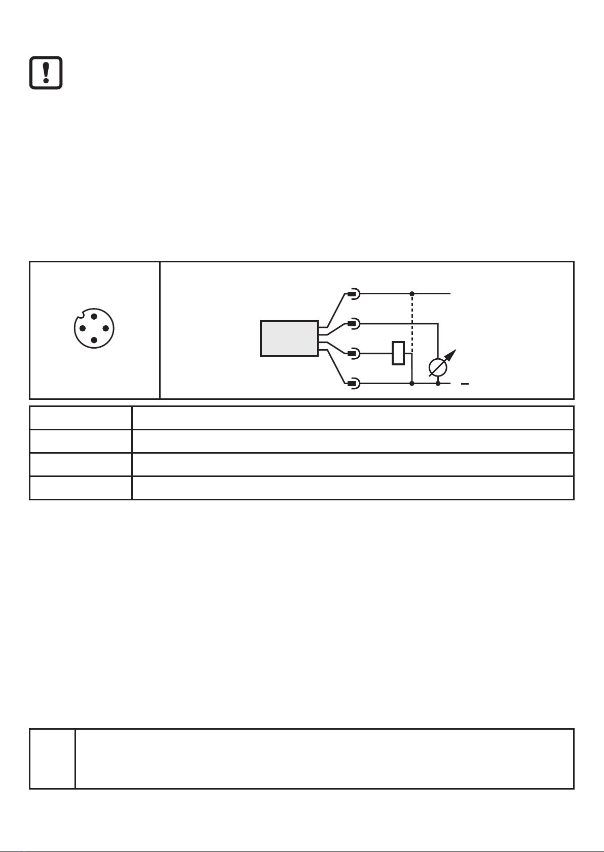
• The unit provides a temperature-proportional output signal (4���20 mA or
20...4mA).
• The measuring range is scalable�
• In addition to the analogue signal the unit provides a diagnostic signal� Sensi-
tivity and reaction to different error modes can be programmed� Pin 4 = output
fordiagnosticsignal(pnpornpn).
4.1 Monitoring and diagnostic functions
• By measuring with two different, thermically coupled sensor elements (NTC,
Pt1000)theunitautomaticallydetectsdriftsanderrorsduringtemperature
measurement with great reliability�
• If one of the two sensor elements fails, the temperature measurement can be
continuedwiththesecondelement(backupfunction).
• Very long-term stable measurement is achieved by using high-quality sensor
elements�
4.1.1 Drift / fault monitoring
To monitor the drift the unit compares the temperatures of two different sensor ele-
ments that are thermically coupled in the sensor tip� Normally these temperatures
are identical�
Due to the usual manufacturing tolerances a temperature difference of max� 0�1 K
can also occur with new sensor elements� This does not affect the drift monitoring
function�
If there is a drift in one or both sensor elements, the unit detects them due to the
difference between the two measured temperatures� It compares the difference
withthesetwarning/alarmthresholds(drW,drA→7Parametersetting).Ifthe
thresholds are exceeded, it generates corresponding diagnostic messages and
sets the corresponding status for the process value�
In case of high temperature changes in the measured medium (e�g� filling of a
hotmediumintoacoldvessel)theremaybeashort-termdifferencebetweenthe
temperatures of both measuring elements� This is based on the corresponding
specific response dynamics of the measuring elements� To prevent a drift warning
or alarm in these cases, a delay time can be set by means of the parameter ddr�

5
UK
4.1.2 Sensor backup / redundancy switching
If one of the two temperature measuring channels fails (e�g� short circuit of one of
thetwosensorelements)thetemperaturecanstillbemeasuredwiththechannel
whichisstilloperational(sensorbackup).However,driftmonitoringisnotpossible
any more�
The characteristics of the unit if one measuring element fails is defined by means
of the parameter drEd�
4.1.3 Response of the outputs in case of a fault
Fnr Type of fault drEd = OFF drEd = On drEd = Ondr
DA AA DA AA DA AA
0 No fault, no anomaly occurred� N T N T N T
10 Fault during power-on self test� A F A F A F
20 Internal malfunction in the sensor
electronics� A F A F A F
21
Partial malfunction in the sensor
electronics, measurement with one
channel still possible�
A F W T/B W T/B
30 Short circuit in switching output Out1
(diagnosticoutput). X T X T X T
40 Malfunction on the analogue output� A X A X A X
41 Load for analogue output of too high
impedance� A X A X A X
42
Analogue signal at the lower limit value,
no linear transmission of the measured
value possible any more� Measured
temperature is below ASP value�
W T W T W T
43
Analogue output at the upper limit value,
no linear transmission of the measured
value possible any more� Measured
temperature has exceeded AEP value�
W T W T W T
51
Interruption measuring element 1
(NTC).
A F W T/B W T/B
52 Short circuit measuring element 1
(NTC). A F W T/B W T/B
53
Temperature of the probe above
the operating temperature range
(170°C).
A F A F A F
54
Temperature of the probe below the
operatingtemperaturerange(-32°C).
A F A F A F

6
Fnr Type of fault drEd = OFF drEd = On drEd = Ondr
DA AA DA AA DA AA
59 Both sensor elements faulty� A F A F A F
61 Interruption measuring element 2 (Pt
1000). A F W T/B W T/B
62
Short circuit measuring element 2 (Pt
1000).
A F W T/B W T/B
71 Detected sensor drift exceeds warn-
ing level� W T W T W T
72 Detected sensor drift exceeds alarm
level� A X A X A F
91 Supply voltage outside the operating
voltage range� W T W T W T
92 Operating temperature of the elec-
tronics outside the specified range� W T W T W T
•Diagnosticstatesofthediagnosticoutput(DA)
- N: nominal operation, no faults detected�
- W: warning: anomaly detected, operation with restricted accuracy or functionality possible�
- A: alarm: fault detected, reliable operation not possible any more� The output signal of the
diagnostic output depends on the setting of the parameter dOU�
- X:undefined(adefinedreactionoftheoutputcannotbeguaranteedincaseofafault).
•Signalsoftheanalogueoutput(AA)
- T: temperature-proportional current signal�
- T/B: temperature-proportional current signal during backup operation�
- F:faultvalue(definedbyparameterFOU).Assoonasnoreliabletemperaturemeasure-
ment is possible any more, a fault level is provided in all cases�
- X:undefined(adefinedreactionoftheoutputcannotbeguaranteedincaseofafault).

7
UK
4.2 Analogue function
• [OU] defines whether the set measuring range is provided as a 4 ��� 20mA
signal([OU]=[I])orasa20...4mAsignal([OU=[InEG]).
• The analogue start point [ASP] defines at which measured value the output
signalis4mA(20mAfor[InEG]).
• The analogue end point [AEP] defines at which measured value the output
signalis20mA(4mAfor[InEG]).
Minimum distance between [ASP] and [AEP] = 50°C / 90°F�
Factory setting Measuring range scaled
1
: [OU] = [I];
2
:[OU]=[InEG]
Behaviour in case of exceeding or not reaching the limits of the measuring
range
• Measured temperature above the set measuring range:
- The output signal rises to max� 20�5 mA / falls to min� 3�8 mA�
- With a further increase of the measured temperature the diagnostic output of
the sensor provides a warning, the fault number Fnr = 43 is set�
• Measured temperature below the set measuring range:
- The output signal falls to min� 3�8 mA / rises to max� 20�5 mA�
- With a further decrease of the measured temperature the diagnostic output of
the sensor provides a warning, the fault number Fnr = 42 is set�

8
5 Installation
Before installing and removing the unit: make sure that no medium is flow-
ing through the installation� Take into account possible dangers which may
arise from extreme plant/medium temperatures�
Aseptoflex adapters ensure that the
sensor can be connected to different
process connections�
(The adapters have to be ordered
separatelyasaccessories.)
Mounting operation:
► Mounttheadapter(B)tothesensor.
►Fix sensor + adapter by means of
a coupling nut, a clamp flange or
similar(A)totheprocessconnec-
tion�
Mounting the Aseptoflex adapter
►Slightly grease the threads and
sealing areas of the sensor and
adapter with the lubricating past�
The paste must be suitable and
approved for the application and
compatible with the elastomers
used�
Recommendation: Klüber paste
UH184-201withUSDA-H1ap-
proval for the food industry�
MakesurethattheO-ring(C)is
correctly positioned�

9
UK
►Screw the sensor into the adapter until it
is hand-tight� Do not damage the sealing
chamfers�
►Clamp sensor and adapter into a clamping
device(D).Tightentheclampingdevice
only slightly so that the adapter does not
warp.Thesealingchamfers(E)mustnotbe
damaged�
►Tighten the sensor using a spanner until
you can feel the end stop (corresponding
to a maximum tightening torque of 25 Nm /
18ftlb).Note:Donotovertighten.Thiscan
have an adverse effect on the sealing�
NOTE: A guarantee for a long-term stable and maintenance-free fitting with no bug
trapsinthehygienicsealingofthemetalseal(Aseptoflexconnection)isonlyvalid
for once-only mounting�
Welding adapter
First weld the adapter, then mount the sensor� Follow the instructions included
with the adapter�
Use in hygienic areas to EHEDG
►Make sure that the sensors are integrated into the system in accordance with
EHEDG.

10
6 Electrical connection
The unit must be connected by a qualified electrician�
The national and international regulations for the installation of electrical
equipment must be adhered to�
Voltage supply according to EN 50178, SELV, PELV�
Referring to UL: For use on a low voltage circuit with overcurrent protec-
tion in accordance with UL873 Tab� 28�1 or Imax = 100/Ub (Ub = voltage
ofthecircuit)..
►Disconnect power�
►Connect the unit as follows:
Pin 1 Ub+
Pin 3 Ub-
Pin 2 (OUT2) Analogue output for system temperature
Pin 4 (OUT1) Diagnostic output
Core colours of ifm sockets:
1=BN(brown),2=WH(white),3=BU(blue),4=BK(black)
7 Parameter setting
► ConnectthesensortoaPCviaIO-Link-Interface(orderno.30396).
►Set the parameters with FDT service program ifm Container: The program is
part of order no� 30396�
The program library of the available DTM objects can be found at www�ifm�com
→Service→Download.
7.1 Adjustable parameters
Uni Display unit
Measuredvalueandsettingvalues(ASP,AEP,drW,drA,COF)canbedisplayedin
the following units: °C ; °F

11
UK
OU Configuration of the analogue output
- I = current output 4���20 mA�
- Ineg = current output 20���4 mA�
ASP Analogue start point
Measuredvalueatwhich4mA(20mAifOU=Ineg)isprovided.
AEP Analogue end point
Measuredvalueatwhich20mA(4mAifOU=Ineg)isprovided.
Minimum distance between ASP and AEP: 50°C / 90°F�
Setting range: ASP AEP in steps of
°C -25���100 40���150 0�05
°F -13���212 104 ���302 0�1
FOU Response of the analogue output in case of a fault
- FOU=ON:Theanaloguesignalgoestothevalue(21.1mA).
- FOU=OFF:Theanaloguesignalgoestothevalue(3.5mA).
dOU Configuration of the diagnostic output
[nc] Normallyclosed(DESINAcharacteristics,wire-breakcanbedetected)
Nominal operation: Diagnostic output active*
Fault warning: Diagnostic output active*
Fault alarm: Diagnostic output inactive
[nc+] Normallyclosedextended(wire-breakcanbedetected)
Nominal operation: Diagnostic output active*
Fault warning: Diagnosticoutputprovides2-Hzsignal*
Fault alarm: Diagnostic output inactive
[no+] Normally open extended
Nominal operation: Diagnostic output inactive
Fault warning: Diagnosticoutputprovides2-Hzsignal*
Fault alarm: Diagnostic output active*
[Hb] Heartbeat(wire-breakandshortcircuitonthewireofthediagnosticcan
bedetected)
Nominal operation: Diagnosticoutputprovides4-Hzsignal*
Fault warning: Diagnosticoutputprovides2-Hzsignal*
Fault alarm: Diagnostic output inactive
*pnp or npn, depending on the setting of the parameter P-n
P-n Output polarity of the diagnostic output
2 settings can be selected:
PnP = positive switching / nPn = negative switching�

12
drEd Characteristicsoftheredundancyswitching(backup)
[OFF] Fault in the electronics: Analogue signal at fault value*
Both sensor elements defective: Analogue signal at fault value*
One sensor element defective: Analogue signal at fault value*
[drW] and [drA] exceeded: Analogue signal corresponds to the
measured temperature�
[On] Fault in the electronics: Analogue signal at fault value*
Both sensor elements defective: Analogue signal at fault value*
One sensor element defective: Analogue signal corresponds to the
temperature of the 2nd measuring
element(backup).
[drW] and [drA]
exceeded:
Analogue signal corresponds to the
measured temperature�
[Ondr] Fault in the electronics: Analogue signal at fault value*
Both sensor elements defective: Analogue signal at fault value*
One sensor element defective: Analogue signal corresponds to the
temperature of the 2nd measuring
element(backup).
[drW] exceeded: Analogue signal corresponds to the
measured temperature�
[drA] exceeded: Analogue signal at fault value*
*corresponds to the setting of the parameter FOU
ddr Delay of the drift detection
By means of this function short exceeding of the drift thresholds can be filtered out
(e.g.incaseoflargetemperaturegradients).
ddr value = time for which a drift value must be above the warning / alarm thresh-
old(drW,drA)inordertoactivatethediagnosticoutput.
Setting range: 0 ��� 300 minutes, in steps of 0�5 minutes�
If the operating voltage is interrupted during the delay time, the unit stores the
remaining time� If the drift persists after re-activation of the operating voltage, the
delay becomes active again until the remaining time has elapsed�
drW Drift warning threshold
Value at which OUT1 provides a warning message according to the configuration�
Setting range: 0�2 ��� 5 °C / 0�4 ��� 9 °F, in steps of 0�05 °C / 0�1 °F�
drA Drift alarm threshold
Value at which OUT1 provides an alarm message according to the configuration�
Setting range: 0�2 ��� 5 °C / 0�4 ��� 9 °F, in steps of 0�05 °C / 0�1 °F�

13
UK
7.2 Service functions
Fnr Fault number
Display of a fault number for detailed fault analysis
rES Reset to factory settings
Click on the respective reset button�
HI
LO
Min-Max memory for system temperature
•HI:displaysthehighestmeasuredtemperature.
•LO: displays the lowest measured temperature�
Erase the memory: Click on the respective reset button�
It is recommended to erase the memory as soon as the unit starts working under
normal operating conditions�
8 Operation
Afterpoweron,theunitisintheRunmode(=normaloperatingmode).Itcarries
out its measurement and evaluation functions and provides output signals accord-
ing to the set parameters�
In case of faults / anomalies:
►Connect the unit to a PC and activate [Fnr]�
8.1 Fault indication
Fnr Type of fault Remedy
0No fault, no anomaly occurred� -/-
10 Fault during power-on self test� ►Switch the supply voltage/switch off
and on again�
►Replace the unit�
20
Internal malfunction in the sensor electronics�
►Replace the unit�
21 Partial malfunction in the sensor elec-
tronics, measurement with one channel
still possible�
►Replace the unit�
(Sensorbackupispossible).*
30 Short circuit in switching output Out1
(diagnosticoutput).
►Check wiring and load on Out1;
temperature measurement without
diagnosis still possible�
40 Fault on the analogue output� ►Check wiring�
►Replace the unit�
41 Load for analogue output of too high
impedance�
►Check wiring and load on Out2;
measured temperature value avail-
able via IO-Link�
*[drEd] = [On] or [Ondr]�

14
Fnr Type of fault Remedy
42 Analogue signal at the lower limit value,
no linear transmission of the measured
value possible any more� Measured
temperature is below ASP value�
►Set ASP value (AEP value if [OU] =
[InEG])lowerifpossible,orreduce
medium temperature�
43 Analogue output at the upper limit value,
no linear transmission of the measured
value possible any more� Measured tem-
perature has exceeded AEP value�
►Set AEP value (AEP value if [OU] =
[InEG])higherifpossible,orreduce
medium temperature�
51 Interruptionmeasuringelement1(NTC). ►Replace the unit�
(Sensorbackupispossible).*
52 Shortcircuitmeasuringelement1(NTC). ►Replace the unit�
(Sensorbackupispossible).*
53 Temperature of the probe above the
operatingtemperaturerange(170C°).
►Reduce medium temperature�
54 Temperature of the probe below the
operatingtemperaturerange(-32°C).
►Increase medium temperature�
59 Both sensor elements faulty� ►Replace the unit�
61 Interruption measuring element 2
(Pt1000)
►Replace the unit�
(Sensorbackupispossible).*
62 Short circuit measuring element 2
(Pt1000).
►Replace the unit�
(Sensorbackupispossible).*
71 Detected sensor drift exceeds warning
level�
First indication of drift detected�
►Prepare replacement of the unit�
►Check whether the parameter [drA] is
programmed correctly�
72 Detected sensor drift exceeds alarm
level�
Drift exceeds alarm threshold�
Temperature measurement with reduced
accuracy possible�
►Replace the unit�
►Check whether the parameter [drA] is
programmed correctly�
91 Supply voltage outside the operating
voltage range�
►Check the supply voltage; ensure a
correct voltage supply�
92 Operating temperature of the electronics
outside the specified range�
►Check the temperature of the upper
part of the unit�
►Adhere to the specified temperature
range�
*[drEd] = [On] or [Ondr]�

15
UK
9 Scale drawing
Dimensions in mm
1: Aseptoflex thread
2: sealing chamfer
TAD161 TAD961
L1 100 40
L2 114�3 54�3
L3 207�2 147�2
L4 221 161

16
10 Technical data
Measuring range [°C / °F]..................................................................... -25 ...150 / -13...302
Operating voltage [V].......................................................................................... 20...32 DC
Current consumption [mA]..................................................................... < 23 (at Ub = 24 V)
Current rating [mA] ......................................................................................................... 250
Short-circuit protection (pulsed); protected against reverse polarity and overload
Integrated watchdog
Analogue output ................................................................................ 4...20 mA / 20...4 mA
Max. load current output [Ω] .......................................................................... (Ub - 10) x 50
Power-on delay time [s]...................................................................................................... 4
Accuracy 1)
- Drift monitoring [K] ............................... ± 0.2 (-10...100 °C); ± 0.3 (-25...-10/100...150 °C)
- Process value [K] ................................ ± 0.2 (-10...100 °C); ± 0.3 (-25...-10/100...150 °C)
Resolution
- Drift monitoring [K]........................................................................................................0.05
- Process value [K] .........................................................................................................0.05
Housing materials.................................................. stainless steel 316L / 1.4404; PEI; FPM
Materials (wetted parts)........ stainless steel 316L / 1.4404; surface characteristics: Ra 0.6
Operating temperature electronics [°C] ............................................................... -25 ... +70
Operating temperature process connection [°C] .................................................. -32...+170
Storage temperature [°C] ..................................................................................... -40 ... +85
Perm. overload pressure [bar].......................................................................................... 50
Protection .......................................................................................................IP 67 / IP 69K
Protection class ..................................................................................................................III
Shock resistance [g] .............................................................. 50 (DIN / IEC 68-2-27, 11 ms)
Vibration resistance [g]..................................................20 ( DIN / IEC 68-2-6, 10-2000 Hz)
EMC EN 61000-4-2 ESD: ...................................................................... 4 kV CD / 8 kV AD
EN 61000-4-3 HF radiated: ............................................................................ 10 V/m
EN 61000-4-4 Burst: ........................................................................................... 2 kV
EN 61000-4-6 HF conducted: ............................................................................ 10 V
1) Probe immersed completely in the medium up to the metal sealing chamfer.

17
UK
10.1 Temperature resistance
Maximum operation time depending on the medium temperature
11 Factory setting
Factory setting User setting
OU I
ASP 0.0
AEP 150.0
drW 0.2
drA 0.5
dOU nc+
FOU On
drEd Ondr
ddr 30
p-n PnP
Uni °C
More information at www�ifm�com
This manual suits for next models
2
Table of contents
Other IFM Transmitter manuals