Sens EnerGenius DC User manual

SENS EnerGenius® DC Wallbox Technical Manual
1
SENS Part Number: 101335
Document Revision: A
DCN Number: 107839
Date: May 4, 2020
PATENTED US 9,270,140; 9,385,556; 9,413,186; 9,509,164;
9,466,995; 9,948,125; 10,575,433
Installation or service questions?
Call SENS between 8 a.m. and 5 p.m. (Mountain Time),
Monday through Friday, or visit our website.
Copyright © Stored Energy Systems LLC 2020
The SENS name / logo, EnerGenius, HELIX, and Dynamic Boost are trademarks of Stored Energy Systems LLC
Installation & Operation Manual
WALLBOX
Automatic Battery Charger/Power Supply
1840 Industrial Circle
Longmont, CO 80501
Phone: 303.678.7500
800.742.2326
Fax: 303.678.7504
Web: www.sens-usa.com

SENS EnerGenius® DC Wallbox Technical Manual
2
TABLE OF CONTENTS
2MODEL NUMBER BREAKOUT.............................................................................................................................. 6
3PERFORMANCE SPECIFICATIONS........................................................................................................................ 7
4SYSTEM OVERVIEW........................................................................................................................................... 10
4.1. Physical Overview ....................................................................................................................................10
4.2. Functional Overview ................................................................................................................................10
4.2.1. Configuration ...........................................................................................................................................10
5MOUNTING INSTRUCTIONS.............................................................................................................................. 12
5.1. Mounting Location...................................................................................................................................12
5.2. Mounting Instructions.............................................................................................................................. 12
6SETUP AND WIRING.......................................................................................................................................... 14
6.1. Wire Ratings and Sizes .............................................................................................................................14
6.2. Grounding Instructions and Connection..................................................................................................16
6.3. DC Connection..........................................................................................................................................16
6.4. AC Connection..........................................................................................................................................17
6.5. Standard Alarm Connections ...................................................................................................................17
6.6. Optional Pilot Relay Connections.............................................................................................................19
6.7. CANbus and RS-485 Connections............................................................................................................. 20
6.8. Ethernet ...................................................................................................................................................22
6.9. SENSbus Connection ................................................................................................................................22
Figure 10 –SENSbus Connection............................................................................................................................23
6.10. Verify Connections...................................................................................................................................23
7START-UP PROCEDURE ..................................................................................................................................... 24
7.1. Connect Battery/Outputs.........................................................................................................................24
7.2. Verify Configuration.................................................................................................................................24
7.3. Apply AC Input Voltage ............................................................................................................................25
7.4. Power Off .................................................................................................................................................25
8ALARMS, LEDS AND DISPLAY............................................................................................................................ 26
8.1. LED Indicators...........................................................................................................................................26
8.2. Individual Alarm Relay Contacts...............................................................................................................26
8.3. LCD Panel .................................................................................................................................................27
8.4. Alarm Definitions .....................................................................................................................................27
9OPERATION ....................................................................................................................................................... 33
9.1. Charging Algorithms................................................................................................................................. 33
9.2. Float Mode...............................................................................................................................................34
9.3. Dynamic Boost™ Mode............................................................................................................................34
9.4. HELIX Mode..............................................................................................................................................35
9.5. Charging Low or Zero-volt Batteries ........................................................................................................35
9.6. Commissioning Batteries..........................................................................................................................35
9.7. Battery Check...........................................................................................................................................35
9.8. Shunt Trip AC Breaker - optional..............................................................................................................36
9.9. Restore Factory Defaults..........................................................................................................................36
9.10. Keypad Operation ....................................................................................................................................36
9.11. Configuration with SENS Setup Utility .....................................................................................................41
9.12. Temperature Compensation....................................................................................................................41
9.13. Load Share Charger Operation.................................................................................................................42
9.14. Efficiency..................................................................................................................................................42
10 SERVICE AND MAINTENANCE........................................................................................................................... 43
10.1. Recommended Annual Maintenance.......................................................................................................43
10.2. Power Module Access..............................................................................................................................43
10.3. Air Filter....................................................................................................................................................44
10.4. Fans.......................................................................................................................................................... 44
10.5. Supplemental Surge Protectors ...............................................................................................................44
11 MODBUS COMMUNICATIONS.......................................................................................................................... 45
11.1. TCP/IP Modbus—Optional .......................................................................................................................45

SENS EnerGenius® DC Wallbox Technical Manual
3
11.2. RS-485 Modbus—Optional......................................................................................................................45
11.3. Modbus Holding Registers .......................................................................................................................45
11.4. Basic Charging Alarms Bit Definition........................................................................................................47
11.5. Charging Status Bit Definition.................................................................................................................. 48
11.6. Charging Alarms Extended Bit Definition.................................................................................................48
11.7. Charging AC Alarms Bit Definition............................................................................................................49
11.8. Accessory Channel Alarms Bit Definition .................................................................................................49
11.9. Accessory System Alarms Bit Definition...................................................................................................49
11.10. Accessory Assigned Channel Alarms Bit Definition..................................................................................50
11.11. Writable Control Flags (Coils)...................................................................................................................50
12 TROUBLESHOOTING/ERROR CODES................................................................................................................. 51
12.1. Configuration Error Codes........................................................................................................................51
12.2. Troubleshooting Guide.............................................................................................................................54
13 GLOSSARY.......................................................................................................................................................... 60

SENS EnerGenius® DC Wallbox Technical Manual
4
1IMPORTANT SAFETY INSTRUCTIONS FOR INSTALLER AND OPERATOR
1.1. SAVE THESE INSTRUCTIONS –This manual contains important safety and operating instructions for
EnerGenius® DC Wallbox battery chargers.
1.2. Before using battery charger, read all instructions and cautionary markings on battery charger, battery, and
product using battery.
1.3. Do not expose charger to rain or snow.
1.4. Use of an attachment not recommended or sold by the battery charger manufacturer may result in a risk of
fire, electric shock, or injury to persons.
1.5. This charger is intended for commercial and industrial use. ONLY TRAINED AND QUALIFIED PERSONNEL
MAY INSTALL AND SERVICE THIS UNIT.
1.6. Do not operate charger if it has received a sharp blow, been dropped, or otherwise damaged in any way;
shut off power at the branch circuit protectors and have the unit serviced or replaced by qualified
personnel.
1.7. To reduce risk of electric shock, disconnect the branch circuit feeding the charger before attempting any
maintenance or cleaning. Turning off controls will not reduce this risk.
1.8. Use appropriate lockout / tagout procedures to ensure safety of all personnel installing and servicing this
equipment. The input and output breakers are equipped with provision to lock breakers in the OFF
position.
1.9. WARNING –RISK OF EXPLOSIVE GASES
1.9.1. WORKING IN THE VICINITY OF A LEAD-ACID OR NICKEL-CADMIUM BATTERY IS DANGEROUS.
STORAGE BATTERIES GENERATE EXPLOSIVE GASES DURING NORMAL BATTERY OPERATION. FOR
THIS REASON, IT IS OF UTMOST IMPORTANCE THAT YOU READ THIS MANUAL AND FOLLOW THE
INSTRUCTIONS EACH TIME YOU USE THE CHARGER.
1.9.2. To reduce the risk of battery explosion, follow these instructions and those published by the battery
manufacturer and the manufacturer of any equipment you intend to use in the vicinity of a battery.
Review cautionary markings on these products and on the engine.
1.10. PERSONAL PRECAUTIONS
1.10.1. Someone should be within range of your voice or close enough to come to your aid when you work
near a storage battery.
1.10.2. Have plenty of fresh water and soap nearby in case battery electrolyte contacts skin, clothing, or
eyes.
1.10.3. Wear complete eye protection and clothing protection. Avoid touching eyes while working near a
storage battery.
1.10.4. If battery electrolyte contacts skin or clothing, wash immediately with soap and water. If electrolyte
enters eye, immediately flood the eye with running cold water for at least 10 minutes and get
medical attention immediately.
1.10.5. NEVER smoke or allow a spark or flame in vicinity of battery or engine.
1.10.6. Be extra cautious to reduce risk of dropping a metal tool onto the battery. It might spark or short
circuit the battery or another electrical part that may cause explosion. Using insulated tools reduces
this risk but will not eliminate it.
1.10.7. Remove personal metal items such as rings, bracelets, necklaces, and watches when working with a
storage battery. A storage battery can produce a short circuit current high enough to weld a ring or

SENS EnerGenius® DC Wallbox Technical Manual
5
the like to metal, causing a severe burn.
1.10.8. When charging batteries, charge LEAD-ACID or LIQUID ELECTROLYTE NICKEL-CADMIUM batteries
only. Consult SENS before using with any other type of battery - other batteries may burst and
cause injuries to persons and damage to property.
1.10.9. NEVER charge a frozen battery.
1.10.10. Consult national and local ordinances to determine if additional battery fault protection is
necessary in your installation.
1.11. Preparing Battery For Charge
1.11.1. Be sure area around battery is well ventilated while battery is being charged.
1.11.2. Ensure battery terminals are clean and properly tightened. Be careful to keep corrosion from
coming in contact with eyes.
1.11.3. Add distilled water in each cell until battery acid reaches level specified by battery manufacturer.
Do not overfill. For a battery without removable cell caps, such as valve regulated lead acid
batteries, carefully follow manufacturer’s recharging instructions.
1.11.4. Study all battery manufacturer specific precautions such as removing or not removing cell caps
while charging and recommended rate of charge. The recommended charge current range must
include the rated output current of the charger.
1.12. Charger Location
1.12.1. Locate the charger as far away from the battery as DC cables permit.
1.12.2. Never place the charger directly above or below the battery being charged; gases from the battery
will corrode and damage charger.
1.12.3. Never allow battery acid to drip on charger when reading electrolyte specific gravity or filling
battery.
1.12.4. Do not operate charger in a closed-in area or restrict ventilation in any way.
1.12.5. Do not set anything on top of the charger.

SENS EnerGenius® DC Wallbox Technical Manual
6
2MODEL NUMBER BREAKOUT
D
W
-
F
S
-
120
S
-
100
-
0
-
A
0
A
-
0
00
A
B
-
C
D
-
E
F
-
G
-
J
-
K
L
M
-
N
P
Parameter
Code
Value
A
Product Family
D
EnerGenius DC
B
Enclosure Type
W
Wallbox
C
AC Input Voltage
F
Three Phase - 480VAC
D
AC Interrupt
S
Standard Interrupt Rating (25kAIC)
H
High Interrupt Rating (65kAIC)
E
DC Output Voltage
120
120 VDC
240
240 VDC
F
DC Interrupt
S
Standard Interrupt Rating (10kAIC)
H
High Interrupt Rating (25kAIC), not available on 240VDC units
G
Output Current
120 VDC
240 VDC
025
25A
✓
035
35A
✓
050
50A
✓
✓
075
75A
✓
100
100A
✓
J
Redundancy
0
No Redundancy
1
N+1 Redundancy
K
Communications and
Interface
A
Standard - (LCD, Keypad, 5 Form-C Relays, Ethernet)
B
Standard with Breaker Status
L
Accessory Hardware
0
None
A
High Current AC Alarm Relays (2X 120VAC, 5A)
B
High Current AC/DC Alarm Relays (2X 150VDC 3A / 240VAC 10A)
C
AC Breaker Shunt Trip
D
Option B and Option C
M
Surge Protection
A
Standard Surge Protection
B
Supplemental AC/DC Surge Protection
N
Mounting
0
Wallmount
P
Configuration
00
Standard Configuration
01
PIP Compliant (requires Accessory Hardware selection to be A, B, or D)
##
Factory Specified Custom Configuration

SENS EnerGenius® DC Wallbox Technical Manual
7
3PERFORMANCE SPECIFICATIONS
EnerGenius DC high power industrial/utility class 3-phase battery charger/power supply, specially hardened for
use in harsh industrial environments. Advanced technology switch mode power conversion is significantly smaller
& lighter than conventional line frequency (e.g. SCR) power conversion and, even without a battery connected,
delivers lower output ripple and much faster dynamic response.
Forced ConductionTM cooling keeps the high efficiency power electronics free of dust and dirt, making EnerGenius
DC well-suited for operation in industrial, utility, power plant, and other harsh environments. Two variable speed,
premium ball-bearing fans cool each rectifier. Rectifiers maintain nearly full output capability even if one fan fails.
A fan failure alarm system with local and remote indication enables service dispatch while the second fan
continues to run. The fan module is easily replaced in the field with common tools.
5 standard Form-C contact alarms are factory set and field reconfigurable, with indication via communication
port, front panel LCD and five assignable alarm relays. Two additional pilot relays to switch external loads or
alarms are optional.
Options include supplemental surge suppression, and data communication including Modbus, DNP3 and IEC
61850. Chargers can be equipped with one or multiple communication protocols. Specifications are detailed in
the table below, see following sections for installation and operation instructions.
Table 1 –Specifications
AC input
Voltage, frequency
Full output power: 358-528 VAC 3-phase line to line
connected, 50% power limit from 188-357 VAC. 47-63 Hz.
Input current
24A maximum at 358VAC for maximum configured unit.
Overcurrent protection
3-pole UL 489 listed circuit breaker
25 kAIC standard, 65 kAIC optional, lockable
Loss of phase
Continues operating with current limit reduced to 50%
AC transient protection
Layered electrical transient defenses. Optional UL1449 Type
1 Listed supplemental surge protection, alarmed and with
field replaceable elements, surge capacity rated 75kA 8/20
µs; visual and remote indications.
Loss of phase
Continues operating with current limit reduced to 50%
Efficiency
Up to 95%, see section 9.14
Power Factor and Total
Harmonic Distortion
>.98 typical at maximum rated load current and boost
charge voltage. Total Harmonic Distortion <3%
DC output
Voltage
120 VDC or 240 VDC nominal: 120 VDC: output adjustable
from 8-160V. 240 VDC: output adjustable from 16-320V.
Current
Output limit: 14kW or 100A for 120VDC models, whichever
is less or 14kW or 50A for 240VDC models, whichever is less
Soft Start
System gradually increases current with a maximum of 5
seconds to full-required output
Charging modes
Multi-stage, including float, boost, HELIX and commissioning
charge modes
Current limit
100% current capability subject to temperature limits and AC
voltage limits; field adjustable from 25% to 100%
Charging characteristic
Constant voltage, current limited; patented Dynamic Boost
and HELIX control
Line & load regulation
±0.5%

SENS EnerGenius® DC Wallbox Technical Manual
8
Output Ripple
< 30mV with battery, <100mV off-battery for 120VDC,
<200mV off-battery for 240VDC. Delivers fast-responding,
stable, well-filtered DC without battery.
Step response
8ms typical without battery, to recover within 1% of rated
output voltage from load step change of 50% rated output
current
Output protection
Electronic current limit. 2-pole UL 489 listed circuit breaker.
10 kAIC standard, 25 kAIC optional, lockable
DC surge protection
Layered electrical transient defenses. Optional UL1449 Open
Type 2 Listed supplemental surge protection, alarmed and
with field replaceable elements, surge capacity rated 75kA
8/20 µs; visual and remote indications.
Battery types
Flooded lead-acid, AGM, Ni-Cd, VRLA, and lithium
DC power supply operation
Delivers fast-responding, stable, well-filtered DC without
battery
Battery temp.
compensation
Standard. On-board sensor modifies output voltage when
temperature is between 0°C and+40°C. Slope adjustable,
factory set to –0.18% per degree C. Optional remote battery
monitor provides battery temperature probe.
Dead battery charge
Starts into and recharges zero-volt battery
Parallel/load share
operation
Two or more independent chargers actively current share
and synchronize all modes for increased current or fault
tolerance when common RJ-45 network cable is connected
to each charger’s paralleling bus
Output blocking protection
Prevents sparking during battery connection or during hot
swap operation
Adjustment &
Controls
Charge mode control
Fully automatic patented Dynamic Boost system. Manual
boost, timed boost & battery commissioning charging
options are available from front panel control
Front panel control
Change all parameters including voltages, current limits,
alarm parameters, relay assignments, network
configurations, time-outs, and more
Local computer
Change all parameters, troubleshoot, create/save
configuration files for quick download to chargers using
network connection and SENS Setup Utility software
available at www.sens-usa.com
Status reporting
LEDs
Two multi-color front panel status LEDs
Metering
DC Voltmeter accurate to ±2%; DC ammeter to ±5%; AC
Voltmeter to +2%; AC ammeter to +5%; AC frequency meter
to ±1.5%; DC Output Watts; DC Output as a percent of
maximum rated output
Status display
20-character display of status & alarm messages.
Data logging
Data logging to internal nonvolatile memory, based on
events and at fixed times. Logs retrieved using computer
network connection.
Alarms
Alarm Outputs
Factory set, field reconfigurable, latching and non-latching.
Alarms available via communication port, alarm relays, and
on LCD.

SENS EnerGenius® DC Wallbox Technical Manual
9
Alarm Inputs
Two optional input contacts (via optional battery monitor) to
monitor status of, and modify charger operation based on,
external devices such as battery room fan or hydrogen
monitor.
Alarm Form C contacts
Five Form C contacts, rated 30V, 2A resistive, assignable.
Two optional 120VAC, 5A, resistive or 150VDC, 3A / 240VAC,
10A assignable
Optional pilot relay
functions
Form C contacts configurable as pilot relays to switch
external loads based on user-configurable conditions
Networking
Modbus communications
Optional Modbus RS-485 or TCP/IP on RJ-45 port
DNP3
Optional DNP3 RS-485 or TCP/IP on RJ-45 port
IEC 61850
Optional IEC 61850 TCP/IP on RJ-45 port
SENSbus
Proprietary bus for connection of paralleled chargers and
SENS accessories
Environmental
Operating temperature
-40C to +70C; full spec from -40C to +50C. Display may be
unreadable and suffer reduced life above 65°C. Cold starts
down to -40°C.
Ingress protection
IP 20; NEMA 1
Humidity
5% to 95%, non-condensing
Altitude
0-6,500 ft (2,000 meters). Above this altitude, output is
derated 0.012% per additional meter at rated ambient
temperature.
Vibration & shock
resistance
EN60068-2-6, EN 60068-2-64 & EN 60068-2-27
Electrical transient
ANSI/IEEE C62.41, EN 61000-4-12 on power terminals, IEC
61000-6-5 and ANSI/IEEE C37.90
Abuse
protection
Reverse polarity
Charger self-protects without output protective device
clearing. Indication via LED & LCD.
Wrong voltage battery
Charger-battery voltage mismatch shuts down charger after
5 minutes. Indication via LED & LCD.
Overvoltage shutdown
Selective; shutdown only operates the overvoltage
shutdown is caused by the charger itself
Overtemperature
protection
Gradual output power reduction if heatsink temperature
becomes excessive; recovery is automatic.
Regulatory
Compliance
North America
C-UL Listed for US & Canada: CSA 22.2, No. 107.2, UL 1012,
UL 508A
NFPA-70, NEMA PE-5, PIP (optional)
FCC Part 15, Class A commercial use and ICES-003 (Canada)
European Union (CE)
EMC: 2014/30/EU (EN 61000-6-2 & EN 61000-6-4)
LVD: 2014/35/EU (EN 60335-1 & EN 60335-2-29)
RoHS 2: 2017/2102/EU (EN 50581)
Construction
Housing
Wall mount
Housing material
Aluminum with powder coated finish
Weight
85 lbs (38.6kg) maximum
Cable entry
Side entry with one 1-1/2 inch NPT opening for DC and two 1
inch NPT openings for AC and two 1/0 inch NPT for
alarms/comms

SENS EnerGenius® DC Wallbox Technical Manual
10
Network/Alarm
connections
Modbus: RJ-45 or terminal blocks 28 to 16 AWG. Form C
alarms: 28 to 16 AWG.
Power connections
AC breaker: 14 –1/0AWG
DC breaker: 1AWG –350kcmil
4SYSTEM OVERVIEW
4.1. Physical Overview
Figure 1 –EnerGenius DC Wallbox Overview
4.2. Functional Overview
4.2.1. Configuration
Each EnerGenius DC Wallbox System comes factory configured for its application from the factory.
Configuration details are given on the configuration label (see Figure 2). These values are assigned
according to the profile configuration selected during the customer order. Profiles are available
for various battery types and applications. Some of the available configuration options may not be
applicable to a given installation. Adjustments to settings can be made via the front panel keypad
or the SENS Setup Utility software via ethernet connection of the EnerGenius DC Wallbox unit to a
computer.

SENS EnerGenius® DC Wallbox Technical Manual
11
Figure 2 –Configuration Label (on inside lower cover)
4.2.2. Standard Items
4.2.2.1. AC Input Breaker, UL 489 listed. The breaker is lockable in the OFF position.
4.2.2.2. DC Output Breaker, UL 489 listed. The breaker is lockable in the OFF position.
4.2.2.3. Five Form C Relays Contacts for Alarm Relays
4.2.2.4. Ethernet communications
4.2.2.5. SENSbus communications
4.2.3. Factory Optional Items
4.2.3.1. Supplementary Surge Protectors
Supplementary Surge Protectors provide additional AC and DC protection in surge intensive
environments. These protectors are equipped with field-replaceable modules that can be
replaced when the surge protective device needs replacement. Alarm and status information
of the surge protective devices is included.
4.2.3.2. Pilot Relays
Pilot Relays are available for connection of external loads and alarms. Two pilot relays are
provided. The first relay is factory assigned as a summary alarm. These are configurable
using the SENS Setup Utility.
4.2.3.3. High Interrupt AC and DC Breakers
Optional high interrupt AC and DC breakers provide higher short circuit current ratings.
4.2.3.4. Shunt Trip AC Breaker
Optional Shunt trip AC Breaker provides overvoltage input overvoltage protection by turning
off the AC input breaker when the input voltage reaches a certain adjustable level.
4.2.3.5. Breaker Status
Breaker Status provides indication and alarms when the AC and DC breakers are in open or
tripped positions.
4.2.3.6. Software
Optional communication protocols include Modbus (TCP/IP and RS-485), DNP3 (TCP/IP and
RS-485) and IEC 601850
4.2.3.7. Module Redundancy
The EnerGenius DC Wallbox can be factory ordered with N+1 redundancy. This provides an
additional power module than is required to meet the rated output. The modules will actively

SENS EnerGenius® DC Wallbox Technical Manual
12
share the load up to the rated current of the unit. Should a power module fail, the remaining
module will support the connected system load and battery recharge demand.
4.2.4. Channelization
EnerGenius DC Wallbox units are equipped with a feature called channelization. Channelization
allows for multiple chargers to be assigned to different output channels called A, B, C, or D.
Multiple units can be assigned to a common load or units can be allocated to separate outputs for
multiple unique loads. All of the channelized EnerGenius DC Wallbox units on a common
communication bus can be controlled / monitored from a single point. Each unique load should
be assigned to a unique channel. For further information on channelization and multi-channel
systems, see specific SENS channelization manual documentation.
5MOUNTING INSTRUCTIONS
INSTALLATION OF THE UNIT MUST COMPLY WITH LOCAL ELECTRICAL CODES AND OTHER APPLICABLE
INSTALLATION CODES AND BE MADE ACCORDING TO THE INSTALLATION INSTRUCTIONS AND ALL APPLICABLE
SAFETY REGULATIONS.
Printed circuit boards contain static sensitive components. Damage can occur even when static levels are too low
to produce a noticeable discharge shock. To avoid static discharge damage, handle the charger by the chassis
only. Remove the cover only when access is essential for installation and service and replace it promptly when
finished.
5.1. Mounting Location
See diagrams at back of manual for dimensions and mounting information.
5.1.1. Charger is rated IP20.
5.1.2. Charger will operate at full specification when located where temperatures are within -40°C
(-40°F) to +50°C (122°F). Output power is gradually reduced at higher temperatures.
5.1.3. Leave clear space for ventilation all around the charger: at least 17.5 inches (44.5 cm) at the top;
at least 4 inches (10.16 cm) at the bottom; at least 4 inches (10.16 cm) on each side. Operating
temperature ranges stated above assume stated clearances.
5.1.4. Mount to a wall or other vertical support. The mounting surface must safely support the weight of
the charger and the fixed wiring. Charger weighs 87 lbs (39.5 Kg).
5.1.5. Allow sufficient room for routing the fixed wiring to the charger. All field connections enter the
charger from the side. See diagrams at back of manual for further information.
5.1.6. Do not mount the charger above any heat generating equipment or where it could get wet.
5.2. Mounting Instructions
5.2.1. The wallbox can be installed without the power modules installed. It is recommended to keep the
modules installed for ease of installation. However, if desired for lighter lifting, remove the power
modules (see section 10.2) before installing the wallbox. These modules can be accessed by
removing the module access cover on the top of the unit (see Figure 1). To remove a module first
unlock the module by moving the cam latch to the unlock position. Then pull the module
upwards to remove. Each module weighs 23 pounds, so it may require significant force to remove
the module after it is in the unlocked position.

SENS EnerGenius® DC Wallbox Technical Manual
13
5.2.2. Drill four wall mounting holes using dimensions provided on diagrams at back of manual.
WARNING:
PROTECT UNIT FROM ALL DRILL SHAVINGS AND DEBRIS!
IF INSTALLING UNIT WITHOUT POWER MODULES INSERTED, USE A FLASHLIGHT TO
VISUALLY INSPECT AND REMOVE CONSTRUCTION DEBRIS CONTAMINATION FROM
POWER MODULE CONNECTORS PRIOR TO INSERTION OF POWER MODULES.
5.2.3. Mount the charger before connecting AC, DC, communications and alarm wiring to ensure un-
obstructed access to mounting holes.
5.2.4. Mount the charger using four 3/8 inch (M10) screws with standard flat washers. Mounting
hardware is not included with the charger and must be provided by the installer.
5.2.5. Use keyhole feature of the upper mounting holes to hang the wallbox in its location.
5.2.6. Inspect the connections, busbars, and wiring for any loose debris or damage from installation.
5.2.7. Re-install any removed power modules at this time. Note –if the wallbox contains only one
power module, the blank module cover must remain in place to ensure adequate cooling of the
unit.
5.2.8. Remove clear film from top inlet ventilation openings.
5.2.9. Ensure all ventilation openings are clear and unobstructed.

SENS EnerGenius® DC Wallbox Technical Manual
14
6SETUP AND WIRING
IMPORTANT! The charger is configured at the factory and typically requires no adjustments before operating.
Refer to the label on the inside lower cover for factory configured output and alarm relay assignments. The
charger may be reconfigured using the front panel keypad or by software programming using the SENS Setup
Utility.
All wiring must comply with applicable codes and local ordinances. The field wiring area is accessed by removing
the field wiring access cover by loosening the three captive Philips #2 screws. Use conduit entry holes as shown in
Figure 3.
Figure 3 –EnerGenius DC Wallbox Conduit Openings
WARNING:
ENSURE THAT AC POWER IS DISCONNECTED AT THE MAINS CIRCUIT BREAKER
OR OTHER SAFETY DISCONNECT BEFORE WIRING THE CHARGER
6.1. Wire Ratings and Sizes
6.1.1. All power conductors should be rated for use at 90°C or higher and 600V or higher. Alarm relay
conductors and communications data cable should be rated for use at 75°C or higher.
6.1.2. Coordinate the AC input conductor size with the customer-provided feeder branch circuit
protection device.
6.1.3. For best performance and recharge time, refer to the following table to determine the
appropriate output conductor gauge and length. Use of a remote temperature sensor (see section
9.12) is highly recommended for best charging performance.

SENS EnerGenius® DC Wallbox Technical Manual
15
Table 2 –DC Output Cable Size
Charger
Rated
Output
Current
(Amps)
Wire Size
Resistance
per Foot
(mΩ/Ft.)
Maximum Charger
to Battery
Distance (Ft.)
AWG
mm2
120V
240V
25
14
2.1
2.50
38
76
12
3.3
1.60
60
120
10
5.3
1.00
96
192
8
8.4
0.63
152
304
6
13.3
0.40
240
480
35
14
2.1
2.50
NEC - not allowed
12
3.3
1.60
NEC - not allowed
10
5.3
1.00
69
138
8
8.4
0.63
109
218
6
13.3
0.40
171
342
4
21.2
0.25
274
548
2
33.6
0.16
429
858
50
14
2.1
2.50
NEC - not allowed
12
3.3
1.60
NEC - not allowed
10
5.3
1.00
NEC - not allowed
8
8.4
0.63
76
152
6
13.3
0.40
120
240
4
21.2
0.25
192
384
2
33.6
0.16
300
600
75
10
5.3
1.00
NEC - not allowed
8
8.4
0.63
NEC - not allowed
6
13.3
0.40
80
160
4
21.2
0.25
128
256
2
33.6
0.16
200
400
1/0
53.5
0.10
327
654
2/0
67.4
0.08
410
820
100
10
5.3
1.00
NEC - not allowed
8
8.4
0.63
NEC - not allowed
6
13.3
0.40
NEC - not allowed
4
21.2
0.25
NEC - not allowed
2
33.6
0.16
150
300
1/0
53.5
0.10
245
490
2/0
67.4
0.08
308
616
The above lengths consider the resistance of the battery and cables only and do not take into
account any additional interconnects. The above lengths factor in a maximum voltage drop of 2%
of the nominal voltage. The above lengths are for operation at 25°C/77°F. For high temperature
installations (50°C/122°F) increase wire gauge by 20%.

SENS EnerGenius® DC Wallbox Technical Manual
16
6.2. Grounding Instructions and Connection
6.2.1. Charger must be grounded to reduce risk of electric shock. The charger must be connected to a
grounded, metal, permanent wiring system, or an equipment-grounding conductor (earthing
conductor) must be run with the circuit conductors and connected to equipment-grounding
terminal on charger.
6.2.2. Connect the equipment grounding conductor to the ground lug in the charger (see Figure 1). This
lug is marked with the ground symbol. This should always be the first wire connected and the last
wire disconnected. Tighten connections to torque specified in Table 3.
Table 3 –Ground Allowed Wire Gauge and Torque Requirements
Ground
Connection Type
Allowed Wire Gauge
Required Torque
Tool
Terminal Block
14-4 AWG (2.5-25 mm2)
50.0 In-Lb (5.65 Nm)
Flat Screwdriver
6.3. DC Connection
Ensure that any battery disconnect devices in the system, if used, are opened (battery disconnected from
DC bus). Connect the DC output conductors to the DC output terminal block/breaker in the charger (see
Figures 1-3). Always observe proper polarity of the DC output leads. Always connect the output leads in
the following order –charger output to ungrounded battery terminal, followed by charger output to
grounded battery terminal. If the battery must be disconnected for service, remove the output wiring in
the reverse order. Tighten connections to torque specified in Table 4. Route DC wiring at least ¼ inch
(6 mm) away from AC wiring, alarm wiring, and the circuit board.
Table 4 –DC Allowed Wire Gauge and Torque Requirements
DC Connection
Type
DC Connection Type
Allowed Wire Gauge
Required Torque
Tool
120VDC
Single Box Lug on
Breaker Terminal
1 AWG –300 kcmil
(50-150 mm2)
135 in-lb (15.25 Nm)
M8 hex
240VDC
Single Box Lug on
Breaker Terminal
14 –2 AWG
2.5-35mm2
14-10AWG: 20 in-lb (2.26 Nm)
8AWG: 35 in-lb (3.95 Nm)
6-2AWG: 75 in-lb (8.47 Nm)
M6 hex
Table 5 –DC Output Breaker Rating
Charger Nominal
Output Voltage
(VDC)
DC Breaker
Rating (Amps)
DC Breaker Interrupt
Standard Rating
(KAIC)
DC Breaker Interrupt
Optional Rating
(KAIC)
120
150
10
25
240
70
10
-

SENS EnerGenius® DC Wallbox Technical Manual
17
6.4. AC Connection
This unit is to be permanently connected to the AC circuit and to the battery. The charger is rated to
operate at full power on any AC input within the range of 358-528VAC, 47-63Hz. The unit is rated to
operate at 50% power from 188-357VAC, 47-63Hz.
Ensure that the AC input supply is de-energized. Connect the AC line conductors to the AC input terminal
block/breaker in the charger (see Figure 1). Tighten connections to torque specified in Table 6. Route AC
wiring at least ¼ inch (6 mm) away from DC wiring, alarm wiring, and the circuit board.
Table 6 –AC Allowed Wire Gauge and Torque Requirements
AC Connection Type
Allowed Wire Gauge
Required Torque
Tool
Single Box Lug on Breaker
Terminal
14-1/0 AWG
(2.5-55.0 mm2)
62.0 In-Lb (7.0 Nm)
M4 hex
Table 7 –AC Input Current and Breaker Rating
Charger Nominal
Output Voltage
(VDC)
Charger Rated
Output Current
(Amps)
AC Rated Input
Current
Maximum per
phase
(Amps)
AC Breaker
Rating
(Amps)
AC Breaker
Interrupt
Standard Rating
(KAIC)
AC Breaker
Interrupt
Optional Rating
(KAIC)
120
50
21.6
30
25
65
120
75
21.6
30
25
65
120
100
21.6
30
25
65
240
25
21.6
30
25
65
240
35
21.6
30
25
65
240
50
21.6
30
25
65
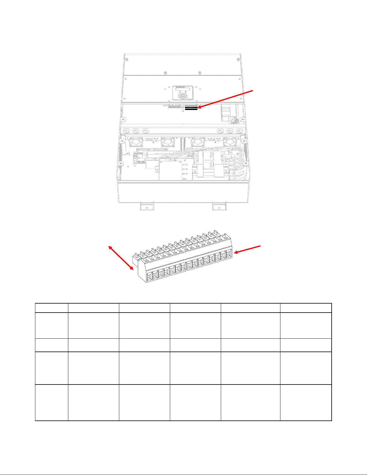
6.5. Standard Alarm Connections
See charger inside cover label for original factory alarm relay assignments (see Figure 2). Alarm relay
assignments are custom configurable using the SENS Setup Utility. Connect alarm wiring to the
respective terminals on the pluggable terminal block in the charger (see Figure 4 for detail). To make
wiring easier, the terminal block unplugs from the header. Pull terminal block straight out from header to
remove. Connect wires to terminal block by tightening screws at each position. After wires are
connected, plug terminal block securely back into header. Wire from FAIL or OK to COM depending on
whether the alarm should be present on an open or closed circuit (see Table 8). Connect alarm terminals
only to low voltage, limited energy (“Class 2”) circuits. Alarm circuits are rated 2A at 30V AC or DC. The
terminals accept 28-16 AWG (0.08-1.5 mm2) conductors. Tighten connections to 2.0 Lb-In (0.22 Nm)
using a small slotted driver. Route alarm wiring at least ¼ inch (6 mm) away from DC wiring, AC wiring,
and the circuit board.
SENS EnerGenius® DC Wallbox Technical Manual
18
Figure 4 –Standard Alarm Connections
(TB1 - pins 1-15 shown)
Table 8 –Alarm Relay Contact Wiring for Stationary Power Configuration
Wire from COM to OK for alarm present on open circuit or from COM to FAIL for present on closed circuit.
RELAY 1
RELAY 2
RELAY 3
RELAY 4
RELAY 5
Relay
Contacts
Summary
Alarm*
AC Fail and
Charger Fail
Battery
Discharging
Alarm
High DC Alarm
Low DC Alarm
Common
COM (TB1-1)
COM (TB1-4)
COM (TB1-7)
COM (TB1-10)
COM (TB1-13)
Open on
alarm
(normally
closed)
OK (TB1-2)
OK (TB1-5)
OK (TB1-8)
OK (TB1-11)
Defaults to OK with
no AC and DC power
OK (TB1-14)
Close on
alarm
(normally
open)
FAIL (TB1-3)
Defaults to FAIL
with no AC input
FAIL (TB1-6)
Defaults to FAIL
with no AC input
FAIL (TB1-9)
Defaults to FAIL
with no AC and
DC power
FAIL (TB1-12)
FAIL (TB1-15)
Defaults to FAIL
with no AC and
DC power
*Summary alarm includes AC Fail, Charger Fail, Battery Discharging, High DC and Low DC alarms.
Functions and operation assigned to each relay are typical. Different functions and assignments are available
both from the factory and by reassignment in the field by users.
5 RELAYS,
3 POSITIONS PER
RELAY:
COM, OK, FAIL
PULL TO REMOVE
FROM HEADER
SENS EnerGenius® DC Wallbox Technical Manual
19
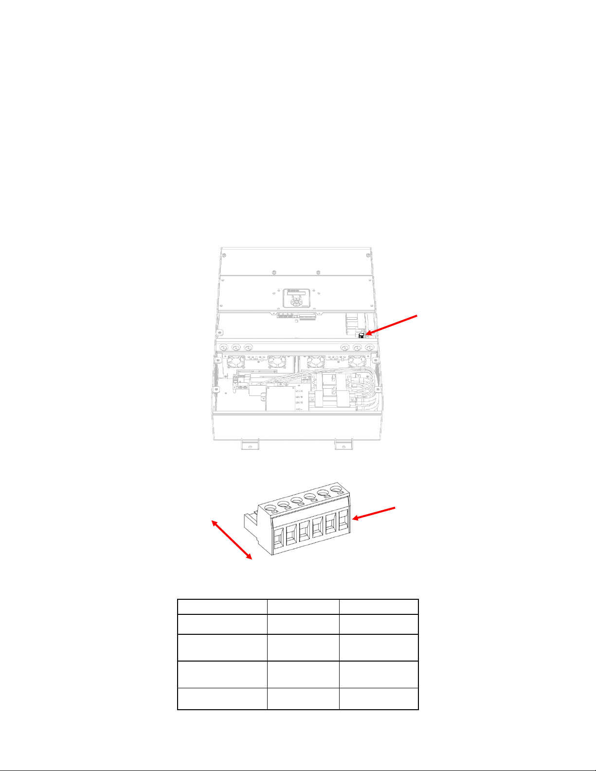
6.6. Optional Pilot Relay Connections
Optional pilot relay relay assignments are custom configurable using the front panel keypad (based on
application) or the SENS Setup Utility. Connect optional alarm wiring to the respective terminals on the
pluggable terminal block in the charger (see Figure 5 for detail). To make wiring easier, the terminal block
unplugs from the header. Pull terminal block straight out from header to remove. Connect wires to
terminal block by tightening screws at each position. After wires are connected, plug terminal block
securely back into header. Wire from FAIL or OK to COM depending on whether the alarm should be
present on an open or closed circuit (See Table 9). There are two type of alarm relay options available
from the factory. The first variant of alarm circuits (2) are rated 5A at 120VAC. The second variant of
alarm circuits (2) are rated 3A at 150VDC and 10A at 240VAC. The terminals accept 26-12 AWG (0.14-4.0
mm2) conductors. Tighten connections to 5.5 Lb-In (0.62 Nm) using a small slotted driver. Route alarm
wiring at least ¼ inch (6 mm) away from DC wiring, AC wiring, low voltage wiring, and the circuit board.
Figure 5 –Optional AC Alarm Connections
(TB1 - pins 1-6 shown)
Table 9 –Optional AC Alarm Connections
Wire from COM to OK for alarm present on open circuit or from COM to FAIL for present on closed circuit.
RELAY 1
RELAY 2
Relay Contacts
Assignable
Assignable
Open on alarm
(normally closed)
OK (TB1-1)
OK (TB1-4)
Close on alarm
(normally open)
FAIL (TB1-2)
FAIL (TB1-5)
Common
COM (TB1-3)
COM (TB1-6)
2 RELAYS,
3 POSITIONS PER
RELAY:
COM, OK, FAIL
PULL TO REMOVE
FROM HEADER
SENS EnerGenius® DC Wallbox Technical Manual
20
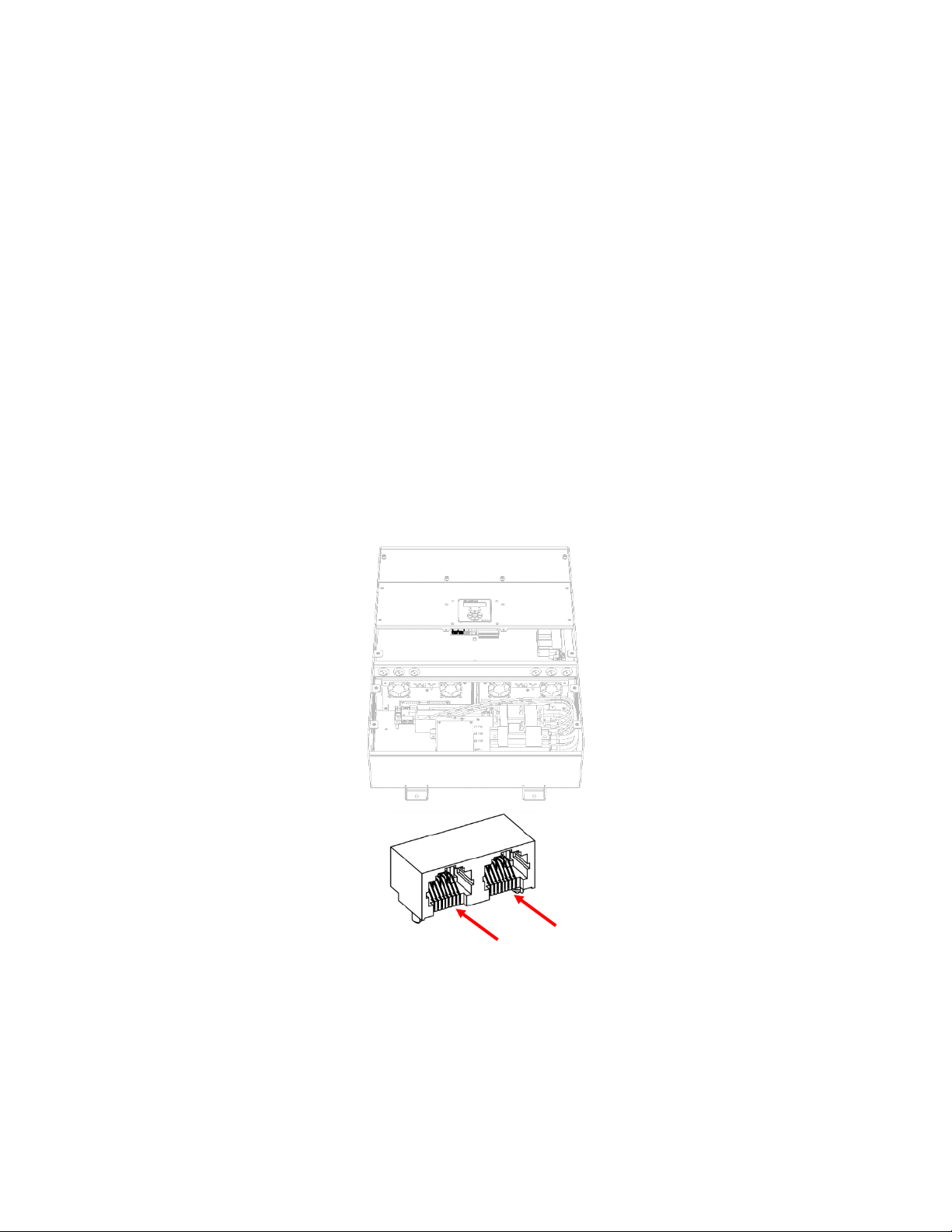
TWO PORTS:
Connect CANbus and/or
Modbus to one or both
ports
Pin 1
Pin 1
6.7. CANbus and RS-485 Connections
Every charger includes CANbus and RS-485 communications via two RJ-45 jacks.
6.7.1. CANbus
The unit is equipped with CANbus communications support via the RJ45 ports. This interface is
intended for communication with customer devices including battery monitoring systems, user
interfaces, and customer-specific CAN protocol communications. Consult the factory for
configuration and setup.
6.7.2. RS-485
The unit is equipped with serial RS-485 communications support via the RJ45 ports. This interface
is intended for monitoring and communicating with the charger. Available protocols include
Modbus and DNP3. See manual sections on specific protocols for more information.
6.7.3. Connection
Connect communications using a twisted pair cable at the RJ-45 connector on the
alarm/communications circuit board located on the inside front cover (see Figure 6 for detail).
Two RJ-45 ports are provided. The ports are in parallel and either port may be used. See Table 10
for connector pinout. Communications are isolated. An adapter from RJ-45 to an 8-position
terminal block may be connected to the RJ-45 connector and is available to order separately
(SENS p/n 208026, see Figure 7).
Figure 6 –CANbus and RS-485 RJ-45 Connections
This manual suits for next models
1
Table of contents
Other Sens Power Supply manuals


Popular Power Supply manuals by other brands


Advanced Energy
Advanced Energy Pinnacle user manual

Xantrex
Xantrex RS232-XHR operating manual

powersoft
powersoft Duecanali Series user guide

American Magnetics
American Magnetics 601 Installation, operation and maintenance instructions

Skyrc
Skyrc eFUEL PSU 30A instruction manual

Emerson
Emerson SMP Series installation guide