Sens PowerCab 2 User manual

SENS PowerCab2 Technical Manual
1
SENS Part Number: 101343
Document Revision: A
DCN Number: 108523
Date: February 27, 2024
PATENTED US 9,270,140; 9,385,556; 9,413,186; 9,509,164;
9,466,995; 9,948,125; 10,575,433
Installation or service questions?
Call SENS between 8 a.m. and 5 p.m. (Mountain Time),
Monday through Friday, or visit our website.
Copyright © Stored Energy Systems LLC 2024
The SENS name / logo, PowerCab, HELIX, and Dynamic Boost are trademarks of Stored Energy Systems LLC
Installation & Operation Manual
PowerCab®2
Factory-packaged Non-stop DC Power Systems
1840 Industrial Circle
Longmont, CO 80501
Phone: 303.678.7500
800.742.2326
Fax: 303.678.7504
Email: service@sens-usa.com
Web: www.sens-usa.com

SENS PowerCab2 Technical Manual
2
TABLE OF CONTENTS
1IMPORTANT SAFETY INSTRUCTIONS FOR INSTALLER AND OPERATOR ............................................................ 4
2PERFORMANCE SPECIFICATIONS........................................................................................................................ 6
3MOUNTING INSTRUCTIONS.............................................................................................................................. 10
3.1. Mounting Location...................................................................................................................................10
3.2. Mounting Instructions.............................................................................................................................. 10
4SETUP AND WIRING .......................................................................................................................................... 11
4.1. Wire Ratings and Sizes .............................................................................................................................11
4.2. Grounding Instructions and Connection ..................................................................................................11
4.3. DC Distribution Connection...................................................................................................................... 11
4.4. AC Connection..........................................................................................................................................12
4.5. Standard Alarm Connections ................................................................................................................... 12
4.6. High Current Relay Connections—Optional............................................................................................. 13
4.7. CANbus Connections................................................................................................................................15
4.8. RS-485 Connections .................................................................................................................................15
4.9. Ethernet ................................................................................................................................................... 16
4.10. Service Connection................................................................................................................................... 17
4.11. Verify Connections ................................................................................................................................... 17
4.12. Verify Covers ............................................................................................................................................17
5START-UP PROCEDURE ..................................................................................................................................... 18
5.1. Connect Battery ....................................................................................................................................... 18
5.2. Verify Configuration.................................................................................................................................18
5.3. Apply AC Input Voltage ............................................................................................................................ 18
5.4. Connect DC Distribution Outputs.............................................................................................................18
5.5. Power Off ................................................................................................................................................. 18
6ALARMS, LEDS AND DISPLAY ............................................................................................................................ 19
6.1. LED Indicators...........................................................................................................................................19
6.2. Individual Alarm Relay Contacts...............................................................................................................20
6.3. LCD Panel .................................................................................................................................................20
6.4. Latched Alarms.........................................................................................................................................20
6.5. Alarm Definitions .....................................................................................................................................20
7OPERATION ....................................................................................................................................................... 26
7.1. Charging Algorithms................................................................................................................................. 26
7.2. Float Mode............................................................................................................................................... 26
7.3. Dynamic Boost™Mode ............................................................................................................................ 26
7.4. HELIX Mode..............................................................................................................................................26
7.5. Charging Low or Zero-volt Batteries ........................................................................................................27
7.6. Commissioning Batteries.......................................................................................................................... 27
7.7. Battery Check ........................................................................................................................................... 27
7.8. Shunt Trip AC Breaker—Optional............................................................................................................. 27
7.9. Restore Factory Defaults.......................................................................................................................... 28
7.10. Keypad Operation ....................................................................................................................................28
7.10.3. Menu Options ..........................................................................................................................................29
7.11. Configuration with SENS Setup Utility ..................................................................................................... 35
7.12. Protocol Communications Circuit Board..................................................................................................35
7.13. Temperature Compensation....................................................................................................................36
7.14. Efficiency ..................................................................................................................................................37
8SERVICE AND MAINTENANCE ........................................................................................................................... 38
8.1. Recommended Annual Maintenance....................................................................................................... 38
8.2. Power Module Access ..............................................................................................................................38
8.3. Air Filter.................................................................................................................................................... 38
8.4. Fans ..........................................................................................................................................................38
8.5. Supplemental Surge Protectors ...............................................................................................................38
9MODBUS COMMUNICATIONS .......................................................................................................................... 39
9.1. TCP/IP Modbus.........................................................................................................................................39

SENS PowerCab2 Technical Manual
3
9.2. Modbus RS-485 ........................................................................................................................................ 39
9.3. Modbus Holding Registers ....................................................................................................................... 40
9.4. Basic Charging Alarms Bit Definition........................................................................................................ 41
9.5. Charging Status Bit Definition ..................................................................................................................42
9.6. Charging Alarms Extended Bit Definition.................................................................................................43
9.7. Charging AC Alarms Bit Definition............................................................................................................43
9.8. Accessory Channel Alarms Bit Definition .................................................................................................43
9.9. Accessory System Alarms Bit Definition................................................................................................... 44
9.10. Accessory Assigned Channel Alarms Bit Definition..................................................................................44
9.11. Writable Control Flags (Coils) - Single coil writes: 0xFF00 for ON, 0x0000 for OFF .................................44
10 DNP3 COMMUNICATIONS—Optional .............................................................................................................. 45
10.1. TCP/IP DNP3.............................................................................................................................................45
10.2. RS-485 DNP3 ............................................................................................................................................45
10.3. SENS DNP3 Config Tool ............................................................................................................................ 45
10.4. Implementation Table.............................................................................................................................. 46
10.5. Binary Inputs ............................................................................................................................................47
10.6. Binary Outputs .........................................................................................................................................49
10.7. Analog Inputs ...........................................................................................................................................50
10.8. Analog Outputs ........................................................................................................................................51
11 NACL SALT BATTERY OPERATION—Optional ................................................................................................... 52
11.1. LED Indication .......................................................................................................................................... 52
11.2. Modbus TCP/IP......................................................................................................................................... 53
12 TROUBLESHOOTING/ERROR CODES................................................................................................................. 58
12.1. Reset Button............................................................................................................................................. 58
12.2. Configuration Error Codes........................................................................................................................ 58
12.3. Troubleshooting Guide............................................................................................................................. 59
13 GLOSSARY.......................................................................................................................................................... 66

SENS PowerCab2 Technical Manual
4
1IMPORTANT SAFETY INSTRUCTIONS FOR INSTALLER AND OPERATOR
1.1. SAVE THESE INSTRUCTIONS –This manual contains important safety and operating instructions for
PowerCab2 DC backup systems.
1.2. Before using system, read all instructions and cautionary markings on battery charger, battery, and product
using battery.
1.3. Use of an attachment not recommended or sold by the backup system manufacturer may result in a risk of
fire, electric shock, or injury to persons.
1.4. This backup system is intended for commercial and industrial use. ONLY TRAINED AND QUALIFIED
PERSONNEL MAY INSTALL AND SERVICE THIS UNIT.
1.5. Do not operate system if it has received a sharp blow, been dropped, or otherwise damaged in any way;
shut off power at the branch circuit protectors and have the unit serviced or replaced by qualified
personnel.
1.6. To reduce risk of electric shock, disconnect the branch circuit feeding the system before attempting any
maintenance or cleaning. Turning off controls will not reduce this risk.
1.7. Use appropriate lockout / tagout procedures to ensure safety of all personnel installing and servicing this
equipment. The AC, BATTERY and CHARGER breakers are equipped with provision to lock breakers in the
OFF position.
1.8. WARNING –RISK OF EXPLOSIVE GASES
1.8.1. WORKING IN THE VICINITY OF A BATTERY IS DANGEROUS. STORAGE BATTERIES MAY GENERATE
EXPLOSIVE GASES DURING NORMAL BATTERY OPERATION. FOR THIS REASON, IT IS OF UTMOST
IMPORTANCE THAT YOU READ THIS MANUAL AND FOLLOW THE INSTRUCTIONS EACH TIME YOU
USE THE CHARGER.
1.8.2. To reduce the risk of battery explosion, follow these instructions and those published by the battery
manufacturer and the manufacturer of any equipment you intend to use in the vicinity of a battery.
Review cautionary markings on these products and on the engine.
1.9. PERSONAL PRECAUTIONS
1.9.1. Someone should be within range of your voice or close enough to come to your aid when you work
near a storage battery.
1.9.2. Have plenty of fresh water and soap nearby in case battery electrolyte contacts skin, clothing, or
eyes.
1.9.3. Wear complete eye protection and clothing protection. Avoid touching eyes while working near a
storage battery.
1.9.4. If battery electrolyte contacts skin or clothing, wash immediately with soap and water. If electrolyte
enters eye, immediately flood the eye with running cold water for at least 10 minutes and get
medical attention immediately.
1.9.5. NEVER smoke or allow a spark or flame in vicinity of battery or engine.
1.9.6. Be extra cautious to reduce risk of dropping a metal tool onto the battery. It might spark or short
circuit the battery or another electrical part that may cause explosion. Using insulated tools reduces
this risk but will not eliminate it.
1.9.7. Remove personal metal items such as rings, bracelets, necklaces, and watches when working with a
storage battery. A storage battery can produce a short circuit current high enough to weld a ring or
the like to metal, causing a severe burn.

SENS PowerCab2 Technical Manual
5
1.9.8. When charging batteries, charge LEAD-ACID, LIQUID ELECTROLYTE NICKEL-CADMIUM, NICKEL-
ZINC or SODIUM-CHLORIDE batteries only. Consult SENS before using with any other type of
battery or changing battery type from originally supplied with system - other batteries may burst
and cause injuries to persons and damage to property. NEVER charge a frozen battery.
1.9.9. Consult national and local ordinances to determine if additional battery fault protection is necessary
in your installation.
1.10. Preparing Battery For Charge
1.10.1. Be sure area around battery is well ventilated while battery is being charged.
1.10.2. Ensure battery terminals are clean and properly tightened. Be careful to keep corrosion from
coming in contact with eyes.

SENS PowerCab2 Technical Manual
6
2PERFORMANCE SPECIFICATIONS
PowerCab2 factory-packaged non-stop DC power systems, specially hardened for use in harsh industrial
environments. Advanced technology switch mode power conversion is significantly smaller & lighter than
conventional line frequency (e.g. SCR) power conversion and, even without a battery connected, delivers lower
output ripple and much faster dynamic response.
Forced ConductionTM cooling keeps the high efficiency power electronics free of dust and dirt, making PowerCab2
well-suited for operation in industrial, utility, power plant, and other harsh environments. Two variable speed,
premium ball-bearing fans cool each rectifier. Rectifiers maintain nearly full output capability even if one fan fails.
A fan failure alarm system with local and remote indication enables service dispatch while the second fan
continues to run. The fan module is easily replaced in the field with common tools.
9 standard Form C contact alarms are factory set and field reconfigurable, with indication via communication port,
front panel LCD and five assignable alarm relays. Four additional high current alarm relays are optional.
Options include various cabinet size/configurations, NEMA 3R ingress protection, fans, heaters, batteries, DC
distribution breakers, supplemental surge suppression, and DNP3 data communications. Modbus data
communications comes standard with each system. Systems can be equipped with multiple communication
protocols. Specifications are detailed in the table below, see following sections for installation and operation
instructions. Multiple systems can be housed in a single cabinet, allowing for full redundancy or dual AC feed
systems.
Specifications
AC input
Voltage, frequency
Full output power: 358-528 VAC 3-phase line to line connected, 50% power
limit from 188-357 VAC. 47-63 Hz.
Input current
96A maximum at 358VAC (for maximum configured unit), see section 4.4
Overcurrent
protection
3-pole UL 489 listed circuit breaker
25 kAIC standard, 65 kAIC optional, lockable. Two breakers optional for dual
AC feed.
Optional breaker status provides indication and alarm when the AC breaker
is in open or tripped position
Optional breaker shunt trip provides input overvoltage damage protection
by turning off breaker when the input voltage exceeds an adjustable level
AC transient
protection
Layered electrical transient defenses. Optional UL1449 Type 1 Listed
supplemental surge protection, alarmed and with field replaceable
elements, surge capacity rated 75kA 8/20 µs; visual and remote indications.
Loss of phase
Continues operating with current limit reduced to 50%
Efficiency
Up to 95%, see section 7.14
Power Factory & Total
Harmonic Distortion
To 0.98 typical at maximum rated load current and boost charge voltage.
Total Harmonic Distortion <3%
DC output
Voltage
120 VDC or 240VDC nominal. 120VDC: output adjustable from 8-160V. 240
VDC: output adjustable from 16-320V. If AC voltage is not applied, charger
powers down below 60VDC.
Current
120VDC output limit: 56kW or 400A, whichever is less.
240VDC output limit: 56kW or 200A, whichever is less.
Soft Start
System gradually increases current with a maximum of 5 seconds to full-
required output
Charging modes
Multi-stage, including float, boost, HELIX and commissioning charge modes
Current limit
100% current capability subject to temperature limits and AC voltage limits;
field adjustable to max rated current.

SENS PowerCab2 Technical Manual
7
Charging
characteristic
Constant voltage, current limited; patented Dynamic Boost and HELIX
control
Line & load regulation
±0.5%
Output ripple
<30mV with battery, <100mV off-battery for 120VDC, <200mV off-battery
for 240VDC. Delivers fast-responding, stable, well-filtered DC without
battery.
Step response
8ms typical, to recover within 1% of rated output voltage from load step
change of 50% rated output current
Output protection
Electronic current limit. 2-pole UL 489 listed charger feed and battery main
circuit breakers.
Output ≤200A: 10 kAIC standard, 25 kAIC optional. Output >200A: 50 kAIC
standard, 100 kAIC optional. Lockable.
Optional breaker status provides indication and alarm when the Charger
breaker is in open or tripped position
DC distribution
Internal panel, 2-pole UL 489 circuit breakers, 22 or 34 positions
DC surge protection
Layered electrical transient defenses. Optional UL1449 Open Type 2 Listed
supplemental surge protection, alarmed and with field replaceable
elements, surge capacity rated 75kA 8/20 µs; visual and remote indications.
Includes replaceable fuses, refer to separately provided diagrams.
Batteries
Optional, type lead-acid, NiZn or NaCl (salt), 40-200Ah (varies based on
battery type). Optional battery monitoring.
DC power supply
operation
Delivers fast-responding, stable, well-filtered DC without battery
Battery temp.
compensation
Standard. On-board sensor modifies output voltage when temperature is
between 0°C and+40°C. Slope adjustable, factory set to –0.18% per degree
C. Optional remote battery monitor provides battery temperature probe.
Dead battery charge
Starts into and recharges zero-volt battery
Redundancy
Optional N+1 or N+2 redundancy provides more power modules than are
required to meet the rated output. All modules will actively share the load
up to the rated current of the system. Should a power module fail, each
remaining module will equally share the connected system load and battery
recharge demand.
Output blocking
protection
Prevents sparking during battery connection or during hot swap operation
Output Derating
Input Voltage/#
Phases
% Output
Power
Available
Max. Available Output
Current Per Module*
140VDC
60VDC
30VDC
400-480VAC/3-ph
Full Rating
(7kW)
50A
50A
50A
400-480VAC/1-ph
50% (3.5kW)
25A
50A
50A
208-240VAC/3-ph
50% (3.5kW)
25A
50A
50A
208-277VAC/1-ph
25% (1.75kW)
12.5A
29A
50A
*120V-50A shown, divide current values in half for 240V-25A modules
Auxiliary DC power
supply
Optional, 12-48VDC, 300W, consumes one distribution breaker position
Auxiliary AC inverter
Optional, 120VAC 60Hz or 230VAC 50Hz, 600/1000/1100/2000/3000W
options, consumes one distribution breaker position

SENS PowerCab2 Technical Manual
8
Adjustment &
Controls
Charge mode control
Fully automatic patented Dynamic Boost system. Manual boost, timed
boost & & battery commissioning charging options are available from front
panel control.
Front panel control
Change all parameters including voltages, current limits, alarm parameters,
network configurations, time-outs, and more
Computer adjustment
Change all parameters, troubleshoot, create/save configuration files for
quick download to chargers using network connection and SENS Setup
Utility software available at www.sens-usa.com
Status
reporting
LEDs
Two multi-color front panel status LEDs
Metering
AC/DC Voltmeter accurate to ±1%; AC/DC ammeter to ±1%; AC frequency
meter to ±1.5%; DC Output Watts; DC Output as a percent of maximum
rated output
Status display
20-character display of status & alarm messages.
Alarms
Alarm Outputs
Factory set, field reconfigurable, latching and non-latching. Alarms available
via communication port, alarm relays, and on LCD.
Alarm Inputs
Two optional input contacts (via optional battery monitor) to monitor status
of, and modify charger operation based on, external devices such as battery
room fan or hydrogen monitor.
Alarm Form C
contacts
Nine Form C contacts, rated 30V, 2A resistive, assignable. Up to four
optional 120V, 5A resistive or 150VDC, 3A / 240VAC, 10A assignable.
Pilot relay functions
Form C contacts configurable as pilot relays to switch external loads based
on user-configurable conditions.
Networking
Modbus
Modbus RS-485 on terminal blocks or TCP/IP on RJ-45 port
DNP3
Optional DNP3 RS-485 on terminal blocks or TCP/IP on RJ-45 port
SENSbus
Proprietary bus for connection of paralleled chargers and SENS accessories
Environmental
Operating
temperature
-40°C to +70°C; full spec from -40°C to +50°C. Display may be unreadable
and suffer reduced life above 65°C. Cold starts down to -40°C.
Ingress protection
NEMA1/IP20 or NEMA3R/IP34
System fan
Optional cabinet door fan, thermostat controlled, turns on at +40°C,
includes replaceable fuses, refer to separately provided diagrams
Heater
Optional cabinet heaters, keeps batteries above freezing
Humidity
5% to 95%, non-condensing
Altitude
0-6,500 ft (2,000 meters). Above this altitude, output is derated 0.012% per
additional meter at rated ambient temperature.
Vibration & shock
resistance
EN60068-2-6, EN 60068-2-64 & EN 60068-2-27
Electrical transient
ANSI/IEEE C62.41, EN 61000-4-12 on power terminals, IEC 61000-6-5 and
ANSI/IEEE C37.90 (withstands 4kV line‐to‐line/line‐to‐earth without optional
AC surge protection, 6kV or greater with optional AC surge protection)
Abuse
protection
Reverse polarity
Charger self-protects without output protective device clearing. Indication
via LED & LCD.
Wrong voltage
battery
Charger-battery voltage mismatch shuts down charger after 5 minutes.
Indication via LED and LCD.
Overvoltage
shutdown
Selective; shutdown only operates if charger causes the overvoltage
condition
Overtemperature
protection
Gradual output power reduction if heatsink temperature becomes
excessive; recovery is automatic.

SENS PowerCab2 Technical Manual
9
Regulatory
Compliance
North America
C-UL Listed for US & Canada: UL 508A
NFPA-70, NEMA PE-5, PIP (optional)
FCC Part 15, Class A commercial use and ICES-003 (Canada)
Construction
Housing
Floor mount; integrated key lock
Housing material
Aluminum with powder coated finish or stainless steel
Weight
Refer to separately provided system diagrams for weight information
Cable entry
Rear, bottom or side access, refer to separately provided system diagrams
Network/Alarm
connections
Modbus: RJ-45 or terminal blocks 28 to 16 AWG. Form C alarms: 28 to 16
AWG.
Power connections
AC breaker: 14 –1/0AWG
DC Distribution breakers: ≤20A: 14 –10AWG. >20A: 10 –1/0AWG.

SENS PowerCab2 Technical Manual
10
3MOUNTING INSTRUCTIONS
INSTALLATION OF THE UNIT MUST COMPLY WITH LOCAL ELECTRICAL CODES AND OTHER APPLICABLE
INSTALLATION CODES AND BE MADE ACCORDING TO THE INSTALLATION INSTRUCTIONS AND ALL
APPLICABLE SAFETY REGULATIONS.
Printed circuit boards contain static sensitive components. Damage can occur even when static levels are too
low to produce a noticeable discharge shock. To avoid static discharge damage, handle circuit boards by the
panel they are installed on only. Remove covers only when access is essential for installation and service and
replace promptly when finished.
3.1. Mounting Location
See separately provided system diagrams for dimensions and mounting information.
3.1.1. System is rated NEMA1/IP20 or NEMA3R/IP34.
3.1.2. Charger will operate at full specification when located where temperatures are within -40°C
(-40°F) to +50°C (122°F). Output power is gradually reduced at higher temperatures.
3.1.3. Leave clear space around all system ventilation openings.
3.1.4. The cabinet is intended to be floor mounted. The mounting surface must safely support the
weight of the system and the fixed wiring.
3.1.5. Allow sufficient room for routing the fixed wiring to the system. All field connections wires enter
the system from the rear, top or bottom.
3.1.6. Do not mount the system above any heat generating equipment or where it could get wet.
3.2. Mounting Instructions
3.2.1. Drill floor mounting holes and mount system using dimensions on separately provided system
diagrams. Mounting hardware is not included with the system and must be provided by the
installer.
3.2.2. Mount the system before connecting AC, DC, communications and alarm wiring to ensure
unobstructed access to mounting holes.
3.2.3. Inspect the connections, busbars, and wiring for any loose debris or damage from installation.
3.2.4. Use all mounting points provided on the separately provided system diagrams.
3.2.5. Ensure all ventilation openings are clear and unobstructed.

SENS PowerCab2 Technical Manual
11
4SETUP AND WIRING
IMPORTANT! The system is configured at the factory and typically requires no adjustments before operating.
Refer to the label on the inside front door for factory configured output and alarm relay assignments. The system
may be reconfigured using the front panel keypad or by software programming using the SENS Setup Utility.
All wiring must comply with applicable codes and local ordinances. See separately provided system diagrams for
access covers and conduit entry holes. Disconnect wires to remove covers as needed; do not hang covers from
wires.
WARNING:
OPEN THE SYSTEM AC, CHARGER AND BATTERY BREAKERS TO ENSURE THAT AC AND
BATTERY POWER ARE DISCONNECTED BEFORE WIRING THE SYSTEM
4.1. Wire Ratings and Sizes
4.1.1. All power conductors should be rated for use at 90°C or higher and 600V or higher. Alarm relay
conductors and communications data cable should be rated for use at 75°C or higher.
4.1.2. Coordinate the AC input conductor size with the customer-provided feeder branch circuit
protection device.
4.2. Grounding Instructions and Connection
4.2.1. System must be grounded to reduce risk of electric shock. The system must be connected to a
grounded, metal, permanent wiring system, or an equipment-grounding conductor (earthing
conductor) must be run with the circuit conductors and connected to equipment-grounding
terminal on system.
4.2.2. Connect the equipment grounding conductor to the ground lug located inside the cabinet (see
separately provided system diagrams for location). This lug is marked with the ground symbol.
This should always be the first wire connected and the last wire disconnected. Tighten
connections to torque specified below.
Ground Allowed Wire Gauge and Torque Requirements
Ground
Connection Type
Allowed Wire Gauge
Required Torque
Tool
Barrel lug
14-2/0 AWG (2.5-70 mm2)
14-10AWG: 35.0 In-Lb (3.95 Nm)
8 AWG: 40.0 In-Lb (4.52 Nm)
6-4 AWG: 45.0 In-Lb (5.08 Nm)
3 –2/0 AWG: 50.0 In-Lb (5.65 Nm)
3/16 inch
hex
4.2.3. Two holes for an optional chassis ground connection exist external to the cabinet on one foot.
Connect ground cables using M6 or ¼ inch fasteners as desired. This connection is optional. The
equipment ground lug provided internal to the system (described above) is still required whether
this connection is used or not.
4.2.4. Per UL 508A, the negative output is grounded. Remove or modify the ground cable if a floating or
positively grounded output is required.
4.3. DC Distribution Connection
Ensure batteries are disconnected from DC bus. Connect the DC output conductors to the DC output
distribution breakers in the system. Always observe proper polarity of the DC output leads. DC
distribution breakers accept 14AWG –10AWG wire for ≤20A and 10AWG –1/0AWG wire for >20A.
Tighten connections to torque specified on breakers. Connect DC distribution ground wires to the ground
bar provided near the breakers; ground bar accepts 14 –4AWG wire. Route DC wiring at least ¼ inch
(6 mm) away from AC wiring and alarm wiring. See separately provided system diagrams for more details

SENS PowerCab2 Technical Manual
12
and breaker handles for output breaker current ratings.
Per UL 508A, the negative output is grounded. Remove or modify the ground cable if a floating or
positively grounded output is required.
4.4. AC Connection
This unit is to be permanently connected to the AC circuit and to the battery. The unit is rated to operate
at full power on any 3-phase AC input within the range of 358-528VAC, 47-63Hz. The unit is rated to
operate at 50% power from 188-357VAC, 47-63Hz.
Ensure that the AC input supply is de-energized. Connect the AC line conductors to the AC input breaker
in the system. AC breaker accepts 14 –1/0AWG wire. Tighten connections to torque specified on the
breaker. Connect ground wire to the ground bar provided near the breaker; ground bar accepts 14 –
4AWG wire. Route AC wiring at least ¼ inch (6 mm) away from DC wiring and alarm wiring. See
separately provided system diagrams for more details and breaker handle for input breaker current
rating. See product label on inside front door for input current rating. Note that the input current
conductors and feeder protection must be sized according to the input current shown on the product
label.
4.5. Standard Alarm Connections
See label on inside of system door for original factory alarm relay assignments. Alarm relay assignments
are custom configurable using the SENS Setup Utility. Alarm circuits are rated 2A at 30V AC or DC.
Connect alarm wiring to the respective terminals on the pluggable terminal block. To make wiring easier,
the terminal block unplugs from its header. Pull terminal block straight out from header to remove.
Connect wires to terminal block by tightening screws at each position. After wires are connected, plug
terminal block securely back into header. Wire from FAIL or OK to COM depending on whether the alarm
should be present on an open or closed circuit (see table below). Connect alarm terminals only to low
voltage, limited energy (“Class 2”) circuits. The terminals accept 28-16 AWG (0.08-1.5 mm2) conductors.
Tighten connections to 2.0 Lb-In (0.22 Nm) using a small slotted driver. Route alarm wiring at least ¼ inch
(6 mm) away from DC wiring and AC wiring. P-clamps provided with system (see envelope inside cabinet)
to install and route alarm wiring as desired.
Standard Alarm Connections
9 RELAYS,
3 POSITIONS PER
RELAY:
COM, OK, FAIL
PULL TO REMOVE
FROM HEADER

SENS PowerCab2 Technical Manual
13
Typical Alarm Relay Contact Wiring for Stationary Power Configuration
Wire from COM to OK for alarm present on open circuit or from COM to FAIL for present on closed circuit.
RELAY 1
Non-latching Coil
RELAY 2
Non-latching Coil
RELAY 3
Latching Coil
RELAY 4
Latching Coil
RELAY 5
Latching Coil
Relay
Contacts
Summary
Alarm*
AC Fail and
Charger Fail
Battery
Discharging
Alarm
High DC Alarm
Low DC Alarm
Common
COM (TB1-1)
COM (TB1-4)
COM (TB1-7)
COM (TB1-10)
COM (TB1-13)
Open on
alarm
OK (TB1-2)
OK (TB1-5)
OK (TB1-8)
OK (TB1-11)
OK (TB1-14)
Close on
alarm
FAIL (TB1-3)
Defaults to FAIL
with no AC and
DC power
(normally closed)
FAIL (TB1-6)
Defaults to FAIL
with no AC and
DC power
(normally closed)
FAIL (TB1-9)
FAIL (TB1-12)
FAIL (TB1-15)
RELAY 6
Latching Coil
RELAY 7
Latching Coil
RELAY 8
Latching Coil
RELAY 9
Latching Coil
Relay
Contacts
Summary
Alarm*
Assignable
Assignable
Assignable
Common
COM (TB1-1)
COM (TB1-4)
COM (TB1-7)
COM (TB1-10)
Open on
alarm
OK (TB1-2)
OK (TB1-5)
OK (TB1-8)
OK (TB1-11)
Close on
alarm
FAIL (TB1-3)
FAIL (TB1-6)
FAIL (TB1-9)
FAIL (TB1-12)
*Summary alarm includes AC Fail, Charger Fail, Battery Discharging, High DC and Low DC alarms.
Functions and operation assigned to each relay are typical. Different functions and assignments are available
both from the factory and by reassignment using the SENS Setup Utility.
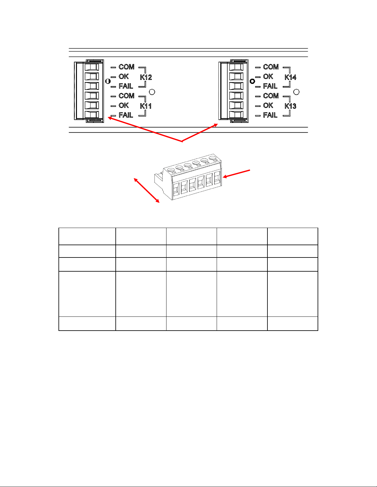
4.6. High Current Relay Connections—Optional
Optional high current relay assignments are custom configurable using the SENS Setup Utility. There are
two high current alarm relay options available from the factory. The first variant of alarm circuits (2) is
rated 5A at 120VAC. The second variant of alarm circuits (2) is rated 3A at 150VDC and 10A at 240VAC.
Connect optional alarm wiring to the respective terminals on the pluggable terminal block. To make
wiring easier, the terminal block unplugs from the header. Pull terminal block straight out from header to
remove. Connect wires to terminal block by tightening screws at each position. After wires are
connected, plug terminal block securely back into header. Wire from FAIL or OK to COM depending on
whether the alarm should be present on an open or closed circuit (see table below). The terminals accept
26-12 AWG (0.14-4.0 mm2) conductors. Tighten connections to 5.5 Lb-In (0.62 Nm) using a small slotted
driver. Route alarm wiring at least ¼ inch (6 mm) away from DC wiring and AC wiring. P-clamps provided
with system (see envelope inside cabinet) to install and route alarm wiring as desired.
SENS PowerCab2 Technical Manual
14
Optional High Current Relay Connections
Optional High Current Relay Connections
Wire from COM to OK for alarm present on open circuit or from COM to FAIL for present on closed circuit.
RELAY 11
Non-latching Coil
RELAY 12
Non-latching Coil
RELAY 13
Non-latching Coil
RELAY 14
Non-latching Coil
Relay Contacts
Assignable
Assignable
Assignable
Assignable
Open on alarm
OK (TB1-1)
OK (TB1-4)
OK (TB1-1)
OK (TB1-4)
Close on alarm
Defaults to FAIL
with no AC and
DC power
(normally closed)
FAIL (TB1-2)
FAIL (TB1-5)
FAIL (TB1-2)
FAIL (TB1-5)
Common
COM (TB1-3)
COM (TB1-6)
COM (TB1-3)
COM (TB1-6)
2 RELAYS,
3 POSITIONS PER
RELAY:
COM, OK, FAIL
PULL TO REMOVE
FROM HEADER
SENS PowerCab2 Technical Manual
15
Pin 1
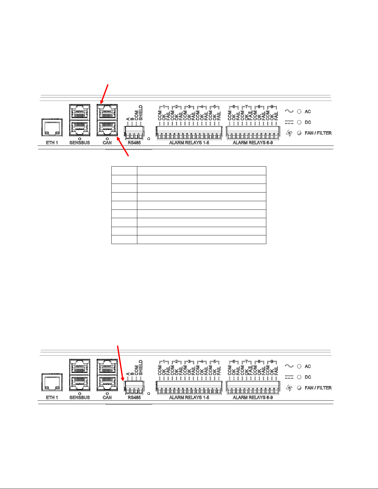
4.7. CANbus Connections
Every system includes CANbus via two RJ-45 jacks. The ports are in parallel and either port may be used.
See table below for connector pinout. Communications are isolated. This interface is intended for
communication with customer devices including battery monitoring systems, user interfaces, and
customer-specific CAN protocol communications. Consult the factory for configuration and setup.
CANbus Connections
Connector Pinout
Pin #
Purpose
1
CANbus
2
CANbus
3
No connect pass-through
4
No connect
5
No connect
6
No connect pass-through
7
Power*
8
Common (isolated)
*Main circuit PCA only, used for interconnect between SENS devices
4.8. RS-485 Connections
Every system includes RS-485 connections via a 4-pin pluggable terminal block. This interface is intended
for monitoring and communicating with the system. Available protocols include Modbus (standard on all
systems) and DNP3 (optional). Use connector position A for Modbus +D1 and position B for Modbus –D0.
The terminals accept 26-12 AWG (0.14-4.0 mm2) conductors. Tighten connections to 5.5 Lb-In (0.62 Nm)
using a small slotted driver. Route alarm wiring at least ¼ inch (6 mm) away from DC wiring, AC wiring,
low voltage wiring, and the circuit board. P-clamps provided with system (see envelope inside cabinet) to
install and route alarm wiring as desired. See manual sections on specific protocols for more information.
RS-485 Connections
4.8.1.1. Termination
For proper Modbus RS-485 operation, a 120-ohm terminator is required at the ends of the RS-
485 bus. If multiple devices are on the bus, only the devices on the ends of the network bus
need termination resistors. The figure below shows an example of how to terminate the
network. Termination may be provided as part of the network cabling or 120-ohm
Pin 1
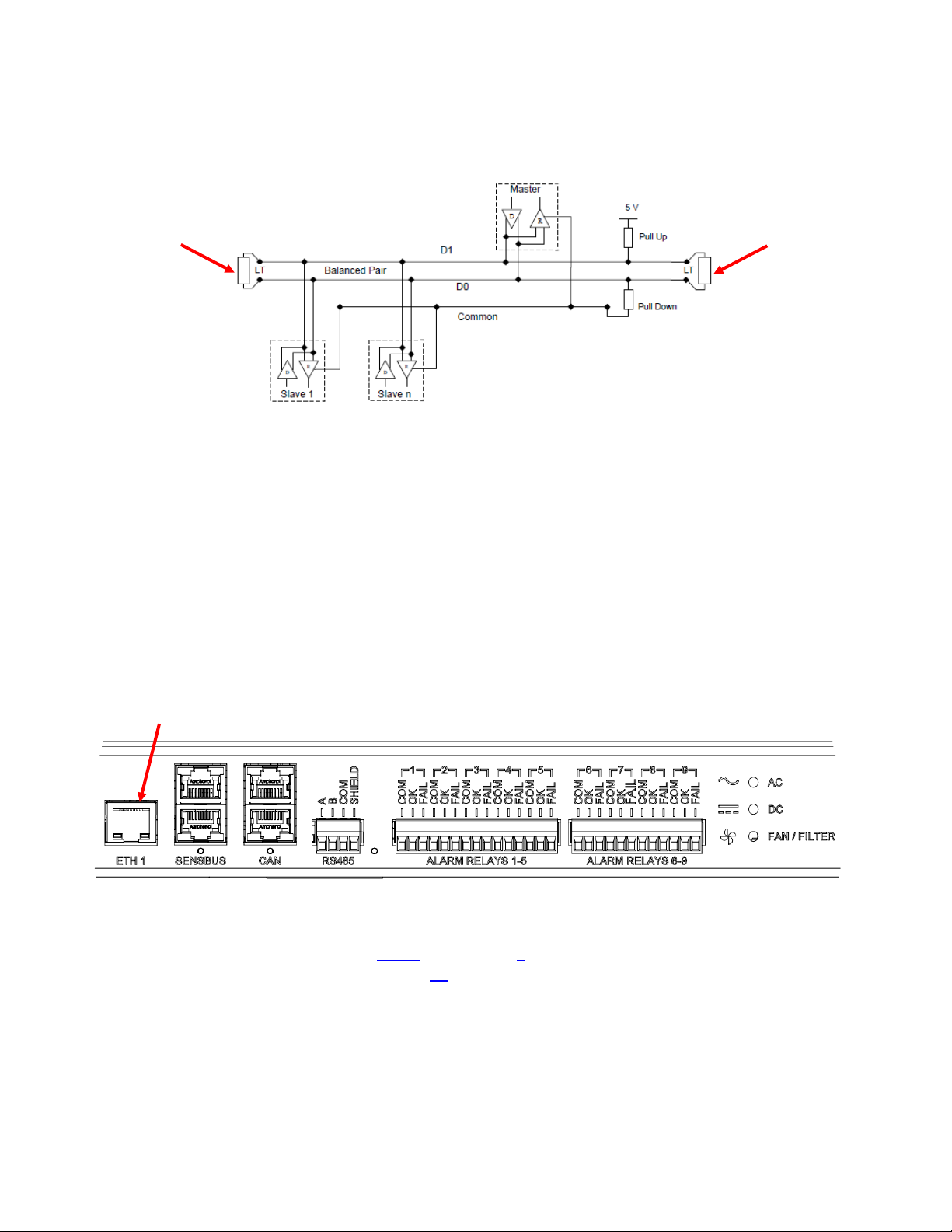
SENS PowerCab2 Technical Manual
16
termination plugs for the RJ-45 communications connector on the system are available to
order separately (SENS p/n 803707). SENS units are slave devices. Pull-up and pull-down
resistors are optional per Modbus specifications.
Typical Modbus Termination
LT = Line Termination 120-ohm resistor
4.9. Ethernet
The unit is equipped with an ethernet RJ45 port (labeled “ETH1”). Connect Cat5 or better ethernet cable.
This provides a 10/100 ethernet connection. P-clamps provided with system (see envelope inside
cabinet) to install and route alarm wiring as desired. Ethernet communications includes ethernet
connectivity to the system for monitoring and configuration via the SENS Setup Utility, Modbus TCP/IP
(standard on all systems) and DNP3 (optional).
Units with NaCl (salt) batteries include an alternate connection for Modbus TCP/IP (labeled “MODBUS
TCP/IP"). Connect Modbus communications to this port instead of ETH1 to receive Modbus information
from the batteries and all devices in the system. See separately provided system diagrams for location in
cabinet. The ETH1 ethernet port is still available but will not include Modbus information from the
batteries. Always use the ETH1 port for connection of the SENS Setup Utility.
ETH1 Ethernet Connection
4.9.1. Configure TCP/IP Address
Configure TCP/IP settings when connected to the ETH1 ethernet port using the SENS Setup Utility
or the keypad (see section 7.10.3). See section 9for Modbus details for all devices in the system
except NaCl batteries. See section 11 for NaCl Modbus details. Set the IP address as desired. It
may take up to 10 seconds for the network setting changes to apply. A TCP/IP address of 0.0.0.0
implies DHCP (Dynamic) addressing. Adjust the Gateway and Subnet Mask values as required. The
“Hardware Address” displayed on the front panel LCD is the MAC address corresponding to the
ETH1 interface. The MAC address for the optional NaCl batteries MODBUS TCP/IP connection is
stated on the label near the connection port. The MAC address values are not adjustable.
SENS PowerCab2 Technical Manual
17
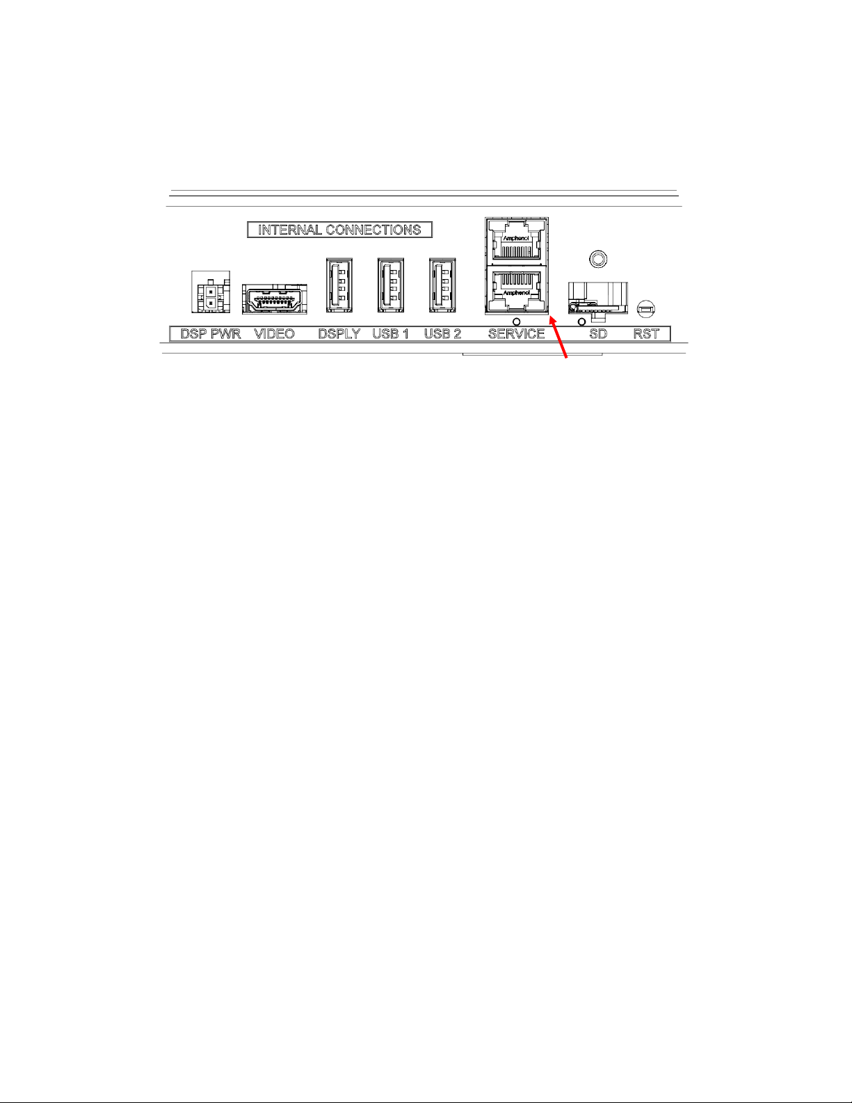
4.10. Service Connection
The unit is equipped with a Service RJ45 port. This SENSbus connection is used for internal devices and
SENS accessory connections. Do not connect multiple PowerCab2 systems together using this
connection unless directed to on the separately provided system diagrams.
Service Connection
4.11. Verify Connections
4.11.1. Verify that all connections are secure and in the proper locations. Tighten all unused screws on
terminal blocks to secure them against vibration.
4.11.2. Ensure all wires are routed in a way that access covers and doors or other objects will not pinch
or damage them.
4.12. Verify Covers
4.12.1. Verify that all covers are re-installed. These covers provide the necessary air partition for
cabinet cooling. The air partition extends the entire length from the top to the bottom of the
cabinet.

SENS PowerCab2 Technical Manual
18
5START-UP PROCEDURE
5.1. Connect Battery
Close system BATTERY and CHARGER circuit breakers to connect the battery to the charger.
5.2. Verify Configuration
Each PowerCab2 system comes configured for its application from the factory. Configuration details are
provided on the configuration label. The Config Code indicates charging algorithm and alarm setpoints
configured at the factory. Review and adjust charger configuration using the front panel keypad or the
SENS Setup Utility if factory configured settings require modification. See section 7.10 for additional
details on keypad navigation.
Example Configuration Label (inside front door)
5.3. Apply AC Input Voltage
Verify the AC input is the correct value (188-528 VAC, 47-63 Hz) and apply AC by closing the system AC
circuit breaker.
Depending on the state of charge of the batteries and the load on the DC bus, the system charger may go
into current limit at this time, in which case the output voltage will be reduced as the charger operates in
constant current mode. Eventually as the battery is charged, the charging current demand will taper to a
value below the current limit setpoint of the charger, and the charger will revert to constant voltage
output. Chargers configured to use Autoboost will operate in the boost mode for variable time ranging
from a few minutes to several hours depending on state of charge of the batteries. When in the
Autoboost mode, the charger will automatically revert from boost to float mode if the Autoboost system
has not automatically reverted to float prior to 24 hours. This is a safety feature which, if activated,
should be investigated.
5.4. Connect DC Distribution Outputs
Close each DC distribution breaker to connect external loads and devices to system DC output voltage.
5.5. Power Off
Power system off as necessary by shutting off the AC, CHARGER and BATTERY breakers in any order.

SENS PowerCab2 Technical Manual
19
6ALARMS, LEDS AND DISPLAY
6.1. LED Indicators
The system is equipped with two LEDs on the main display, one for AC status and one for DC status. See
further alarm definitions in section 6.5. See section 11 for optional NaCl (salt) battery LED indicators.
LED Definitions
AC LED
DC LED
Meaning
OFF
OFF
AC and DC not applied or charger failed or
alarm/communications circuit board cannot
communicate with main circuit board
SOLID GREEN
SOLID GREEN
AC good, DC good, in Float Mode
SOLID GREEN
FLASHING GREEN
AC good, in Dynamic Boost Mode
SOLID GREEN
FLASHING 2X GREEN
AC good, DC in current limit (max charge)
SOLID GREEN
FLASH LONG-SHORT GREEN
AC good, HELIX Eco-Float mode
SOLID GREEN
FLASH LONG-2X SHORT GREEN
AC good, HELIX Refresh Charge mode
SOLID GREEN
FLASH LONG-SHORT YELLOW
AC good, battery commissioning mode active
SOLID GREEN
FAST FLASHING GREEN
AC good, battery check in progress
SOLID GREEN
FAST FLASHING YELLOW
AC good, battery check failure
SOLID GREEN
SOLID RED
AC good, charger fail or overvoltage shutdown
(charger disabled)
SOLID GREEN
FLASHING RED/YELLOW
AC good, reverse polarity detected on output
SOLID GREEN
SOLID YELLOW
AC good, high or low DC voltage (above/below
alarm setpoint)
SOLID GREEN
FLASHING GREEN/RED
AC good, system DC output good, some individual
charger module(s) in alarm state
SOLID GREEN
FLASHING RED/YELLOW
AC good, incompatible battery (charger disabled)
SOLID GREEN
FLASHING YELLOW
AC good, positive/negative ground fault present
SOLID GREEN
FLASHING GREEN/YELLOW
AC good, output limited by high temperature
SOLID GREEN
DOUBLE FLASH YELLOW
AC good, load share fail
SOLID GREEN
DOUBLE FLASH RED
AC good, load sharing DC negative connection
open or load sharing charger address fault
SOLID YELLOW
SOLID GREEN
AC voltage/frequency out of range or AC phase
missing, DC voltage good
SOLID RED
SOLID GREEN
AC fail or over max voltage, DC voltage good
SOLID RED
SOLID YELLOW
AC fail, high or low DC voltage (above/below
alarm setpoint)
SOLID RED
SOLID RED
AC fail, charger fail or overvoltage shutdown
(charger disabled)
SOLID RED
FLASHING RED/YELLOW
AC fail, incompatible battery (charger disabled)
SOLID RED
FLASHING YELLOW
AC fail, positive/negative ground fault present
FLASH LONG-2X SHORT YELLOW
SENSbus Inactive
ALTERNATING FLASHING YELLOW
Illegal jumper configuration
ALTERNATING FLASHING RED
Missing or invalid code (boot load required)
ALTERNATING FLASHING GREEN
Charger starting up

SENS PowerCab2 Technical Manual
20
6.2. Individual Alarm Relay Contacts
The standard alarm/communications circuit board offers nine alarm discrete Form C contacts. The Form
C relay contacts change state when alarms are activated. Alarm relay assignments are custom
configurable to any of the alarm functions listed in section 6.5. See configuration label on inside front
door for original factory alarm relay assignments. See section 4.5 for typical alarm relay assignments. The
relays can be configured to be latching or non-latching with adjustable delays using the SENS Setup
Utility.
By default, the relay contacts change state 30 seconds after the onset of a fault. The relay delay is
configurable using the front panel keypad (see section 7.10) or the SENS Setup Utility. See section 6.5 for
alarm definitions.
6.3. LCD Panel
A two line by twenty-character LCD is included with every system and provides precision digital AC and
DC ammeters and voltmeters as well as information about input, output, charging status and alarms. The
voltmeters are accurate to +1% and the ammeters are accurate to +1%. The display is readable with or
without ambient lighting and operates automatically, requiring no operator intervention.
The LCD is fully operational from -20°C to +50°C. It may temporarily become unreadable below -20°C but
should recover as temperature increases. LCD life is reduced with sustained operation above 65°C.
6.4. Latched Alarms
All alarm messages displayed on the front panel LCD are latching. Alarm relay configurations created
using the SENS Setup Utility may be configured as latching if desired. Once an alarm condition no longer
exists, the alarm message will no longer display in the main/home screen but will remain under the
“Latched Alarms” menu. Clear latched alarms using the keypad under the “Latched Alarms” menu (see
section 7.10.3), using the SENS Setup Utility or by cycling power.
6.5. Alarm Definitions
See section 6.1 for a description of LED indicator activity. Unless noted otherwise, the following alarms
are displayed on the LCD panel.
6.5.1. AC Line Failure
Indicates AC input voltage is not detected or is outside of the allowed 188-528VAC range.
Activates solid red AC LED. When this alarm is assigned to a relay contact AC LINE FAIL will cause
the assigned relay to change to the Failed state after the time delay.
6.5.2. High DC Voltage
Indicates DC output voltage is above the High DC Voltage factory alarm setpoint or the configured
level if setpoint is adjusted using keypad or SENS Setup Utility. Activates solid yellow DC LED.
When this alarm is assigned to a relay contact HIGH DC VOLTAGE will cause the assigned relay to
change to the Failed state after the time delay.
6.5.3. Battery on Discharge
Indicates battery is beginning to discharge and DC output voltage is below Battery Discharge
Voltage factory alarm setpoint or the configured level if setpoint is adjusted using keypad or SENS
Setup Utility. The BATTERY DISCHARGING alarm is the first to trigger of three low output voltage
alarms and is followed by LOW DC and then END OF DISCHARGE. Alarm setpoint must be set
higher than LOW DC and END OF DISCHARGE alarms. Activates solid yellow DC LED. When this
alarm is assigned to a relay contact BATTERY DISCHARGING will cause the assigned relay to
change to the Failed state after the time delay.
6.5.4. Low DC Voltage
Indicates battery has discharged and DC output voltage is below Low DC Voltage factory alarm
setpoint or the configured level if setpoint is adjusted using keypad or SENS Setup Utility. Alarm
setpoint must be set lower than BATTERY DISCHARGING and higher than END OF DISCHARGE
Table of contents
Other Sens Power Supply manuals


Popular Power Supply manuals by other brands


PS Audio
PS Audio AV-3000 Owner's reference

Conductix-Wampfler
Conductix-Wampfler 91008-111-3130923 operating instructions

Puls
Puls PIANO PIM60.241 installation manual

Campbell
Campbell PS200 user guide

Riello
Riello STEEL PRO POWER INSTALLATION, TECHNICAL ASSISTANCE SERVICE AND SYSTEM MANAGEMENT MANUAL

Pulsar
Pulsar PSCV5012 quick start guide

Cosel
Cosel LFA10F instruction manual

Electro-Automatik
Electro-Automatik EL 9000 T operating manual

AKO-Agrartechnik
AKO-Agrartechnik EuroGuard N 1400 operating instructions

Keithley
Keithley Series 2200 quick start guide

B+K precision
B+K precision 9130 instruction manual

Fine Vu
Fine Vu FINE Safer S installation manual