Sensata PMP Series User manual

Page 1
Copyright © 2019 Sensata Technologies, Inc.
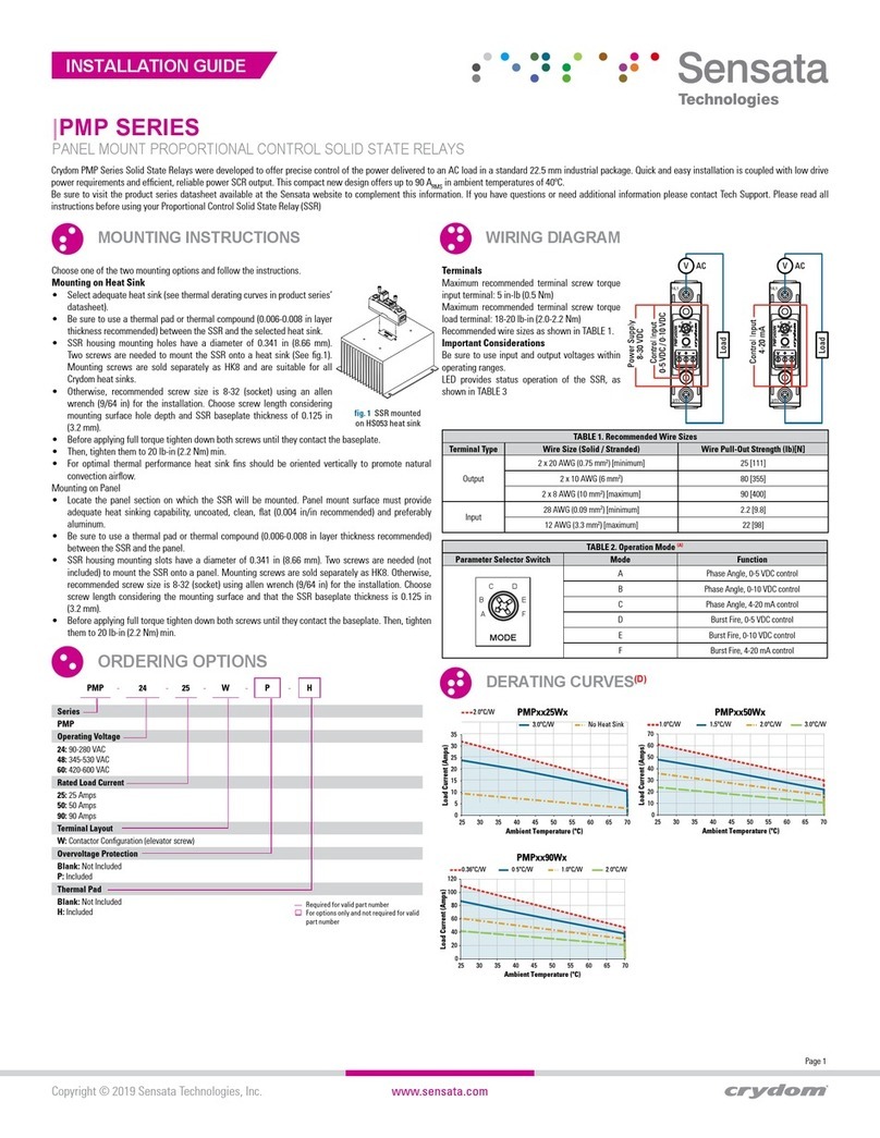
Terminals
Maximum recommended terminal screw torque
input terminal: 5 in-lb (0.5 Nm)
Maximum recommended terminal screw torque
load terminal: 18-20 lb-in (2.0-2.2 Nm)
Recommended wire sizes as shown in TABLE 1.
Important Considerations
Be sure to use input and output voltages within
operating ranges.
LED provides status operation of the SSR, as
shown in TABLE 3
|PMP SERIES
PANEL MOUNT PROPORTIONAL CONTROL SOLID STATE RELAYS
MOUNTING INSTRUCTIONS
ORDERING OPTIONS
WIRING DIAGRAM
Crydom PMP Series Solid State Relays were developed to offer precise control of the power delivered to an AC load in a standard 22.5 mm industrial package. Quick and easy installation is coupled with low drive
power requirements and efficient, reliable power SCR output. This compact new design offers up to 90 ARMS in ambient temperatures of 40ºC.
Be sure to visit the product series datasheet available at the Sensata website to complement this information. If you have questions or need additional information please contact Tech Support. Please read all
instructions before using your Proportional Control Solid State Relay (SSR)
INSTALLATION GUIDE
Choose one of the two mounting options and follow the instructions.
Mounting on Heat Sink
• Select adequate heat sink (see thermal derating curves in product series’
datasheet).
• Be sure to use a thermal pad or thermal compound (0.006-0.008 in layer
thickness recommended) between the SSR and the selected heat sink.
• SSR housing mounting holes have a diameter of 0.341 in (8.66 mm).
Two screws are needed to mount the SSR onto a heat sink (See fig.1).
Mounting screws are sold separately as HK8 and are suitable for all
Crydom heat sinks.
• Otherwise, recommended screw size is 8-32 (socket) using an allen
wrench (9/64 in) for the installation. Choose screw length considering
mounting surface hole depth and SSR baseplate thickness of 0.125 in
(3.2 mm).
• Before applying full torque tighten down both screws until they contact the baseplate.
• Then, tighten them to 20 lb-in (2.2 Nm) min.
• For optimal thermal performance heat sink fins should be oriented vertically to promote natural
convection airflow.
Mounting on Panel
• Locate the panel section on which the SSR will be mounted. Panel mount surface must provide
adequate heat sinking capability, uncoated, clean, flat (0.004 in/in recommended) and preferably
aluminum.
• Be sure to use a thermal pad or thermal compound (0.006-0.008 in layer thickness recommended)
between the SSR and the panel.
• SSR housing mounting slots have a diameter of 0.341 in (8.66 mm). Two screws are needed (not
included) to mount the SSR onto a panel. Mounting screws are sold separately as HK8. Otherwise,
recommended screw size is 8-32 (socket) using allen wrench (9/64 in) for the installation. Choose
screw length considering the mounting surface and that the SSR baseplate thickness is 0.125 in
(3.2 mm).
• Before applying full torque tighten down both screws until they contact the baseplate. Then, tighten
them to 20 lb-in (2.2 Nm) min.
Series
PMP
Operating Voltage
24: 90-280 VAC
48: 345-530 VAC
60: 420-600 VAC
Rated Load Current
25: 25 Amps
50: 50 Amps
90: 90 Amps
Terminal Layout
W: Contactor Configuration (elevator screw)
Overvoltage Protection
Blank: Not Included
P: Included
Thermal Pad
Blank: Not Included
H: Included
PMP -24 -25 -W-P-H
Required for valid part number
For options only and not required for valid
part number
TABLE 1. Recommended Wire Sizes
Terminal Type Wire Size (Solid / Stranded) Wire Pull-Out Strength (lb)[N]
Output
2 x 20 AWG (0.75 mm2) [minimum] 25 [111]
2 x 10 AWG (6 mm2) 80 [355]
2 x 8 AWG (10 mm2) [maximum] 90 [400]
Input 28 AWG (0.09 mm2) [minimum] 2.2 [9.8]
12 AWG (3.3 mm2) [maximum] 22 [98]
TABLE 2. Operation Mode (A)
Parameter Selector Switch Mode Function
MODE
D
E
F
C
B
A
A Phase Angle, 0-5 VDC control
B Phase Angle, 0-10 VDC control
C Phase Angle, 4-20 mA control
D Burst Fire, 0-5 VDC control
E Burst Fire, 0-10 VDC control
F Burst Fire, 4-20 mA control
DERATING CURVES(D)
fig. 1 SSR mounted
on HS053 heat sink
056 222 38 18 mailbox@sentronic.com www.sentronic.com
SENTRONIC AG

Specification No.: Rev. 11/12/18
Americas
+1 (877) 502 5500
Europe, Middle East & Africa
+44 (1202) 416170
Asia Pacific
China +86 (21) 2306 1500
Japan +81 (45) 277 7117
Korea +82 (31) 601 2004
India +91 (80) 67920890
Rest of Asia +886 (2) 27602006
ext 2808
Page 2
CONTACT US
Copyright © 2019 Sensata Technologies, Inc.
Sensata Technologies, Inc. (“Sensata”) data sheets are solely intended to assist designers (“Buyers”) who are developing systems that incorporate Sensata
products (also referred to herein as “components”). Buyer understands and agrees that Buyer remains responsible for using its independent analysis, evaluation
and judgment in designing Buyer’s systems and products. Sensata data sheets have been created using standard laboratory conditions and engineering
practices. Sensata has not conducted any testing other than that specifically described in the published documentation for a particular data sheet. Sensata may
make corrections, enhancements, improvements and other changes to its data sheets or components without notice.
Buyers are authorized to use Sensata data sheets with the Sensata component(s) identified in each particular data sheet. HOWEVER, NO OTHER LICENSE,
EXPRESS OR IMPLIED, BY ESTOPPEL OR OTHERWISE TO ANY OTHER SENSATA INTELLECTUAL PROPERTY RIGHT, AND
NO LICENSE TO ANY THIRD PARTY TECHNOLOGY OR INTELLECTUAL PROPERTY RIGHT, IS GRANTED HEREIN. SENSATA DATA SHEETS ARE PROVIDED “AS
IS”. SENSATA MAKES NO WARRANTIES OR REPRESENTATIONS WITH REGARD TO THE DATA SHEETS OR USE OF THE DATA SHEETS, EXPRESS, IMPLIED
OR STATUTORY, INCLUDING ACCURACY OR COMPLETENESS. SENSATA DISCLAIMS ANY WARRANTY OF TITLE AND ANY IMPLIED WARRANTIES OF
MERCHANTABILITY, FITNESS FOR A PARTICULAR PURPOSE, QUIET ENJOYMENT, QUIET POSSESSION, AND NON-INFRINGEMENT OF ANY THIRD PARTY
INTELLECTUAL PROPERTY RIGHTS WITH REGARD TO SENSATA DATA SHEETS OR USE THEREOF.
All products are sold subject to Sensata’s terms and conditions of sale supplied at www.sensata.com SENSATA ASSUMES NO LIABILITY FOR APPLICATIONS
ASSISTANCE OR THE DESIGN OF BUYERS’ PRODUCTS. BUYER ACKNOWLEDGES AND AGREES THAT IT IS SOLELY RESPONSIBLE FOR COMPLIANCE WITH
ALL LEGAL, REGULATORY AND SAFETY-RELATED REQUIREMENTS CONCERNING ITS PRODUCTS, AND ANY USE OF SENSATA COMPONENTS IN ITS
APPLICATIONS, NOTWITHSTANDING ANY APPLICATIONS-RELATED INFORMATION OR SUPPORT THAT MAY BE PROVIDED BY SENSATA.
Mailing Address: Sensata Technologies, Inc., 529 Pleasant Street, Attleboro, MA 02703, USA.
• The Elevator Screw option allows the screw and clamp
to be raised out of the mating threads completely. This
provides for the insertion and use of a ring or lug type
wire terminal.
• A #2 Phillips head driver should be used with the
Elevator Screws. If a powered driver is used, avoid
speeds above 500 RPM.
• Cutting threads in the cover plastic as the screw
elevates is key to the elevating feature. It has a finite
life and therefore not recommended to be used more
than 50 times during the product lifetime.
• Do not continue rotating the screw (in the elevating
direction) once it freely rotates at the top of the plastic surface. The Elevator screw is capable of
clearing 0.125 inches between the terminal and the bottom of the screw. Insertion of a terminal or
lug thicker than 0.125 in is not recommended.
• When inserting the terminal ensure that the terminal hole is in line with the screw.
• During tightening, be certain that the terminal is seated flat within the cavity, and that the clamping
washer is secure against the upper surface of the terminal.
• If fork terminations, spade lugs, or stranded wire are used, to prevent improper contact do not raise
the elevator screw out of the mating threads.
(A) The operation mode is detected during power up. Any changes done to the selector while the unit is
powered will be ignored until next power up
(B) UL approved rating is the one that intersects at 40°C.
TABLE 5. Recommended Accessories
Hardware Kit Thermal Pad Lug Terminal
Heat Sink
Part No.
Thermal
Resistance [ºC/W]
HK8 HS259DR
HS073
HS072
HS053
HS033
HS023
2.5
0.7
0.7
0.5
0.36
0.25
HSP-7 TRM0
TRM6
ACCESSORIES
ELEVATOR SCREW (”W” SUFFIX)
CONSIDERATIONS
GENERAL NOTES
Status LED Indicator
Flashes twice intermittently
Flashes three times intermittenl y
Flashes four times intermittenl y
Flashes five times intermittenl y
Varying brightness
Varying frequenc y
No Mains Voltage
Frequency Out of Range
Error on Selector
Overtemperature
Phase Control
Burst Control
SSR Output
OFF
OFF
OFF
OFF
ON
ON
Fork LugR ing Lug Copper Lug Copper Lug
Width [W] in (mm)
Terminals
Stud Size Dia [D] (in)
Wire Size AWG
Crydom Part No.
0.45 (11.4)
#8 (0.168)
0.45 (11.4)
#8 (0.168)
TRM0
6-0
TRM6
14-6
W D
W D
fig. 2 Elevator screw
TABLE 3. LED Status TABLE 4. Compatible Terminals
056 222 38 18 mailbox@sentronic.com www.sentronic.com
SENTRONIC AG
This manual suits for next models
1
Other Sensata Relay manuals
Popular Relay manuals by other brands
TE Connectivity
TE Connectivity SRSE-2NO Installation, use and maintenance guide
sprecher + schuh
sprecher + schuh CMR7N Series quick start guide
Micom
Micom ALSTOM P341 Technical data sheet
GEYA
GEYA GRT6-S Series instruction manual
CD Automation
CD Automation REVO SSR user manual
PickData
PickData ACTIO 24 quick start guide
