SensaTyre TPE01A User manual

Tire Pressure Monitoring System
User Manual
Pressure Range:0~80 PSI
Model:TPE01A
(Cap Type)
TPV05A
(Valve Type)
TPV03A
(Valve with Antenna Type)
TPC03A
(Clamp Type)

1
Table of Content
1
2
2
2
2
! " #
! " # ! " #
! " #
3
! $ %
! $ % ! $ %
! $ %
3
! " ! &
! " ! & ! " ! &
! " ! &
4
' ( $ % ) ( !
' ( $ % ) ( ! ' ( $ % ) ( !
' ( $ % ) ( !
9
'
' '
' (
( (
( $ % ( & * ( ! !
$ % ( & * ( ! ! $ % ( & * ( ! !
$ % ( & * ( ! !
9
'
' '
'
" $ % + ) ( !
" $ % + ) ( ! " $ % + ) ( !
" $ % + ) ( !
10
, & ! !
, & ! !, & ! !
, & ! !
11
, ! ! " ! &
, ! ! " ! & , ! ! " ! &
, ! ! " ! &
11
, "& " ! &
, "& " ! & , "& " ! &
, "& " ! &
13
, -
, - , -
, -
14
. /
. / . /
. / 0 #
0 # 0 #
0 #
15
.
. .
. # 1 2 ! ! " !
# 1 2 ! ! " ! # 1 2 ! ! " !
# 1 2 ! ! " !
15
.
. .
. # 3 ! ! " !
# 3 ! ! " ! # 3 ! ! " !
# 3 ! ! " !
16
.
. .
. # "& " !
# "& " ! # "& " !
# "& " !
17
. $ !
. $ ! . $ !
. $ !
17
.
. .
. $ ! )
$ ! ) $ ! )
$ ! ) 4
44
4 !
! !
!
18
. '
. '. '
. ' 5 "6 7
5 "6 75 "6 7
5 "6 7 8
88
8)
))
)
" ! &
" ! & " ! &
" ! &
18
. ,
. ,. ,
. , 9 : / 0 #
9 : / 0 # 9 : / 0 #
9 : / 0 #
19
;
; ;
; 0 #
0 # 0 #
0 #
20
; 9 : 1
; 9 : 1 ; 9 : 1
; 9 : 1
20
; #
; # ; #
; #
2
2 2
2 "
""
" ! & (
! & ( ! & (
! & (
20
;
; ;
; ! ! 0 #
! ! 0 # ! ! 0 #
! ! 0 #
21
;
; ;
; "& 0 #
"& 0 # "& 0 #
"& 0 #
22
;
; ;
; ( ! 1 #
( ! 1 # ( ! 1 #
( ! 1 #
22
; '
; ' ; '
; ' 9 :
9 : 9 :
9 : 0 #
0 # 0 #
0 #
23
<
< <
< $ % ( #
$ % ( # $ % ( #
$ % ( # 444
444444
4441 )
1 )1 )
1 )
!
! !
!
&
& &
& = % > 2
= % > 2 = % > 2
= % > 2
?
? ?
?
"
""
" ! &
! & ! &
! &
23
1 &
1 & 1 &
1 &
26
" !
" ! " !
" !
27
" !
" !" !
" !
28
#
# #
#
31

2
1
Product Introduction
(1) This tire pressure monitoring system contains highly accurate sensors to detect tire
pressure and temperature; and RF modules send data via radio wave to the digital
receiver placed in driver’s cabin.
(2) The tire pressure monitoring system –TPV05A/TPV03A/TPC03A starts to detect
pressure and temperature automatically when the vehicle is in motion. The tire
pressure monitoring system - TPE01A starts to detect pressure and temperature
automatically when the sensor is mounted. Pressure and temperature data will be
showed on the LCD screen of digital receiver. If the pressure and temperature go
wrong, the driver will be warned with LCD backlight, beep, and flashing numbers.
Therefore, the driver can take action immediately.
2
Safety Notice
(1) Tire pressure monitoring system is a vehicle safety warning system. Please follow
installation guide and instruction carefully. When the system sends out warming
signals, please check your tires immediately.
(2) This product has to be properly installed and programmed by professional
technician.
3
Vehicle Application
This product is suitable for “0~80PSI” tire pressure range.
What are Included in the Package
4.1 Digital Receiver1unit
4.2 User Manual1 copy4.3 Antenna1 pcs
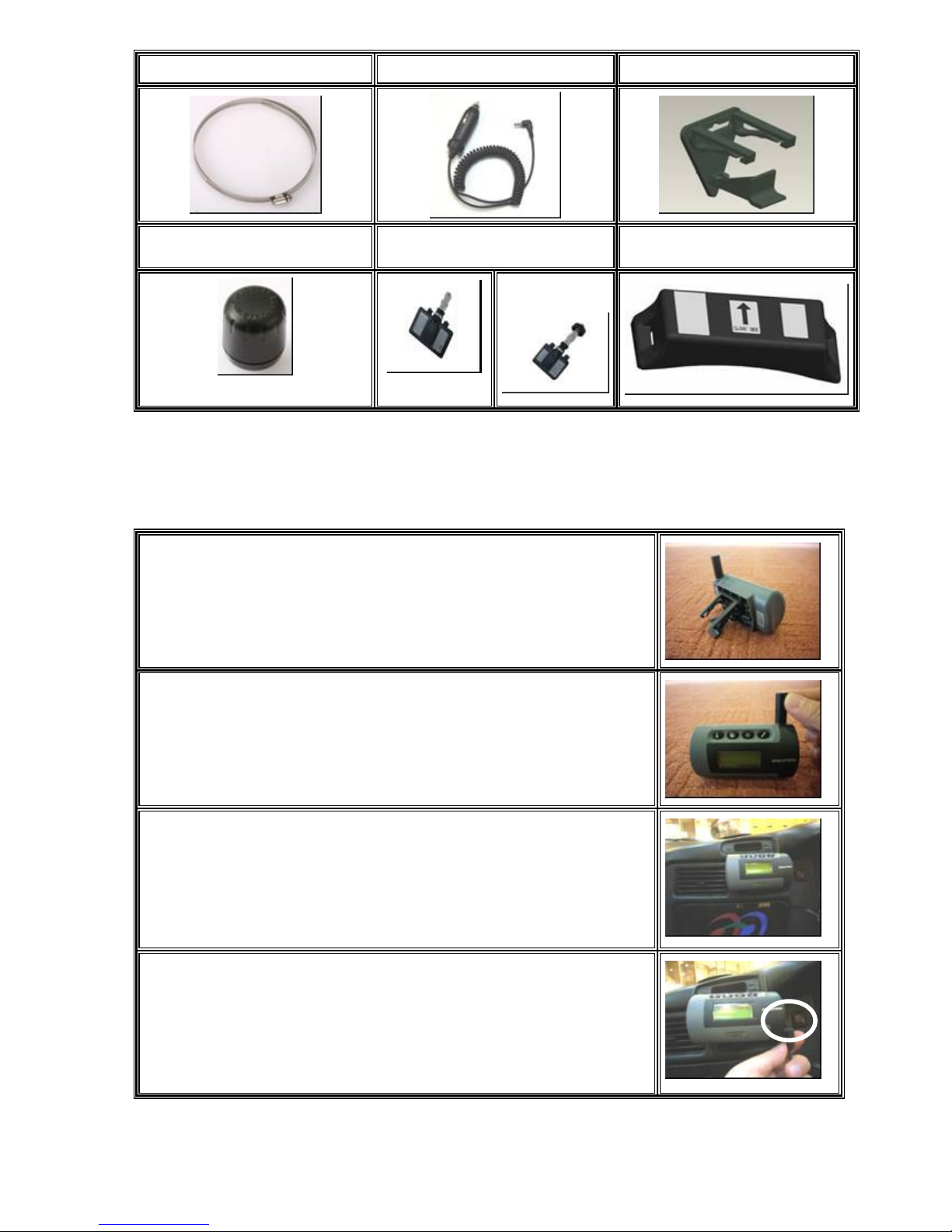
3
4.4 Strap4 pcs4.5 Power Cable1 pcs4.6 Receiver’ Holder 1 pcs
4.7 Transmitter4 pcs4.8 Transmitter4 pcs4.9 Transmitter4 pcs
With Antenna
Installation of TPMS
Install Receiver
(1) Install the Receiver’ Holder on the back of it.
(2) Install the Antenna.
(3) Use the Receiver’s Holder to install the Receiver on the vent
of air conditioner.
(4) Install the Cigarette Lighter Power Cable on the Receiver.

4
(5) Turn on the KEY SW, the Receiver will show??P
(6) Reverse above steps to remove the receiver.
5.2 Install Transmitter
Attention:
Transmitters must be installed by professional technicians. The technicians
have to follow the installation guide step by step to install transmitters correctly.
Following tools and instructions are for technicians, not for end users.
Tools
Tire Changer
Wheel Balancer
Pliers
Other Hand-tools
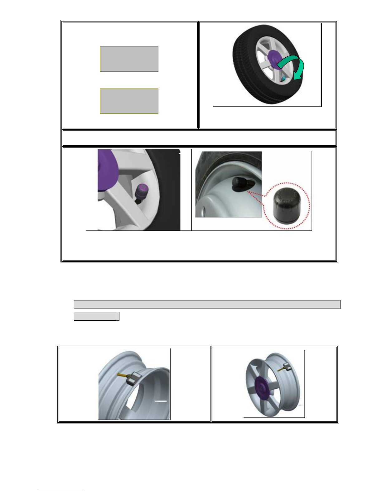
5.2.1 Install Cap Type Transmitter
Please follow steps below to install cap type transmitter. Wheel balancing is
required after the installation.
@ @
@ @@ @
@ @ IMPORTANT: Turn on the Receiver and go to the General Set Up Mode/Search
TX ,then place the transmitter one by one(See NO.8.6)See Page:18
1. Place the transmitter on the valve.
Make sure the one gets the signal
and wait 2 mins to prevent getting
the same ID, then you can go to the
next.
2. Shown as No.1
??P ??P
??P ??P
5
NOTE:NO.8.6(Page 18)
1.1 Search T
1.2 Pick Up tire
1.2
3.Set tightened torque at 9~10 Kgf.cm.
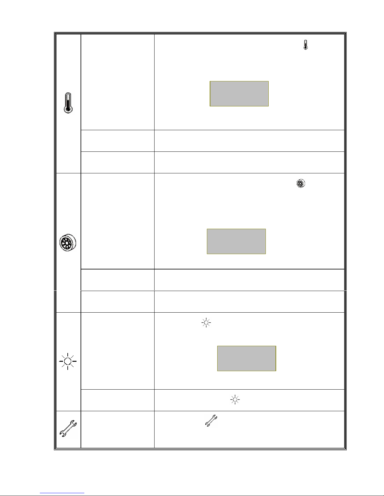
5.2.1 Install Valve Type Transmitter
(Before install the tire please set up the ID of the transmitter first, refer to NO.10)
See Page:23
(1)Install the Valve type into the valve of tire disc.
Search
Tx
01 02
03 04

6
(2)Install the Washer into the valve of Transmitter.
(3)Tighten the Nut into the valve of Transmitter.
Tighten Torque 35~45 Kgf-cm
(4)Tighten the Nozzle into the valve of Transmitter.
Tighten Torque 2~3.2 Kgf-cm

7
(5)Install the tire.
(6)Install the Antenna(Only TPV03A).
(7) Finished.

8
5.2.3 Install Clamp Type Transmitter
(Before install the tire please set up the ID of the transmitter first, refer to NO.10)
See Page:23
5.2.1.1 Please follow the standard procedures
to dismount tire from rim.
IMPORTANT:
5.2.1.2 Set up the ID of the transmitter and
must keep other transmitters away
from at least 1m away to avoid taking
the same signal Then install the
clamp.
5.2.1.3
Make sure arrow on the transmitter
point to rubber valve side.
5.2.1.4 Put the transmitter in the lowest area
of the rim or drop center, and beside
valve. Tighten the strap.(Torqre must
over 0.35 kfg-m)
Suggestion: Place lock of strap opposite to
transmitter mounting position for better tire
rebalancing.
5.2.1.5
Cut excess strap off to approximately
one inch (25mm); blunt sharp cutting
edge.

9
5.2.1.6
Wheel Balancing is required after
transmitter installation.
5.2.1.7
Reverse the above steps to remove
a transmitter.
Suggestion:Tell technician that you have
installed TPMS before he changes the tire.
6. Digital Receiver Function Description
6.1 Digital Receiver Diagram, Display Control and Indicators
Temperature
LCD Backlight
Set Up
Pressure
10
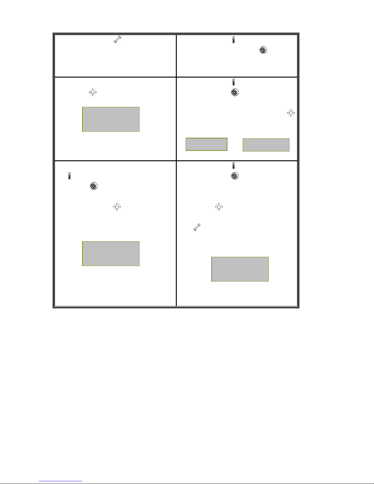
6.2 The Receiver Button Function Description
1.Temperature
Button Display temperature of tires after press button . If no
data
received,
the corresponding tire pressure will be displayed
as “??C”.
2.
(Downward
Button)
In “General Set Up Mode”,acts
as downward button to
select function and number.
3.Backward Button In “Special Set Up Mode”,acts as backward button t
o
select tire for programming.
1.Pressure Button Display pressure of tires after press button .
If no data
received, the corresponding tire pressure will be displayed
as “??P”
2.
(Upward Button)
In “General Set Up Mode”,acts
as upward button to select
function and number.
3.Forward Button In “Special Set Up Mode”,acts as forward
button to select
tire for programming.
1.LCD Display
Backlight Button Press button to switch the backlight of LCD Display.
2.Confirmation
Button In set up mode,button acts as confirmation button.
1.Activate Set Up
Button Press button more than 2 seconds
to enter into
“General Setup Mode”.
35C 35C
??C 36C
32P 32P
??P 32P
32P 32P
32P 32P

11
2.Exit Set Up Mode Press button again to exit “Setup Mode”.
Note
Values shown above are for reference only.
7. Alarms and Warnings
7.1 Pressure Threshold Alarm and Warning
*Remark:
The manual
pressure thresholds suggested being
lower than 29PSI and higher than
42PSI. The pressure threshold
value is adjustable by user.
1. Tire pressure lower/higher than Manual
Pressure Threshold Setting
Low/High Pressure Warning is initiated
when the pressure drops below /rises above
the
programmed Pressure Threshold Setting Limit.
Warning Actions Include
(1) LED Alarming Indicator blinks once.
(2) Two short audio alarms.
Suggested Action to Warning
When the warning occurs, reduce
speed and proceed to a safe
location to check tires.
Example:
When the tire pressure is lower than
threshold, the LCD display will show
something as below and initiate the
pressure warning.
2. Tire pressure drops below the
Factory-Preset Low Pressure Threshold
Setting
Low Pressure Alarm is initiated when the
pressure drops below the Factory-Preset
Threshold Setting Limit.
Alarm Actions Include
(1) LED Alarm Indicator blinks once.
(2) Three short audio alarms.
(3) LCD Display Backlight remains onThe
pressure value of the anomalous tire will be
kept flashing and shown on the associated
tire location.
To Cancel Alarm actions
Proceed “Reset” function as described on
“General Set Up Mode” Section 8.4. Or
Remark:
The low tire pressure warning value
is set as 75% of the cold tire
pressure.
(1) The cold tire pressure for valve
cap transmitter is the initial
pressure detected while the
transmitter screwed on the tire.
(2)The cold tire pressure for clamp
type transmitter is the tire pressure
detected while the transmitter is
waking up by its centrifugal switch.
(if the tire pressure is below 30PSI,
the cold tire will be detected as
30PSI, e.g. the low tire pressure
25P
32P
32P 32P

12
warning value will be 23PSI.
the low pressure warning will remain on the
display even re-power the receiver.
Suggested Action to Alarm
When the alarm occurs,reduce speed and
proceed to a safe location to check tires.
Note
The Pressure Deflation Alarm will disappear
when the tires are properly re-inflated to
correct levels. Example:
When the tire pressure is 10PSI,
the LCD display will remain as
left and the warning will activate.
3. Leak Warning
When the tire pressure decline rate is over
5PSI/minute(fast leaks) or 10PSI/10
minute.(slow leaks), the transmitter will
initiate the warning. The tire pressure and
the !!! warning signal will flash with
interchanging.
NoteThe leak warning might be wrongly initiated
if the tire pressure is dramatically
changed, esp. under the heavy rain or
the significant temperature falls.
Note
Value shown above is for reference only.
!10P 32P
32P 32P
!!! 32P
32P 32P

13
7.2 Temperature Threshold Alarm and Warning
Note:
The default
manual threshold Setting
Limit is 75°C
.
1. Tire Temperature higher than Manual
Temperature Threshold Setting
High Temperature Warning is initiated when
detected tire temperature is above the
programmed Temperature Threshold Setting
Limit.
Warning Actions Include:
(1) LED Alarming Indicator blinks once.
(2) Two short audio alarms.
(3) The pressure value of the associated tire
flashes once
Suggested Action to warming
When the warning occurs, reduce
speed and proceed to a safe location to
check tires.
Example:
When the tire temperature is 80°C,
the LCD display will remain as
below and the warning will
activate.
2. Tire Temperature higher then Factory-
Preset
Temperature Threshold Setting
High Temperature Alarm is initiated when tire
temperature rises above the Factory-Preset
Temperature Threshold Setting Limit.
Alarm Actions Include:
(1) LED Alarming Indicator flashes once.
(2) Three short audio alarms.
(3) LCD Display Backlight remains onThe
temperature value of the
anomalous tire will be kept flashing
and shown on the associated tire
location.
To Cancel Alarm actions
Proceed “Reset” function as depicted on
“General Set Up Mode” Section 8.4. Or
the low temperature warning will remain on
the display even re-power the receiver.
Suggested Action to Alarm
When the alarm occurs, reduce speed and
proceed to a safe location to check tires.
Example:
When the tire pressure is 86°C,the
LCD display will remain as below
and the warning will activate.
Note:
The Factory-Preset
Temperature Threshold Setting Limit
is set at 85°C in the transmitter
firmware.
80C 35C
35C 35C
!86C 35C
35C 35C

14
7.3 Other Warnings
1. Communication failure warning
When the receiver has not received a
transmitter signal over 30 mins., the ???
symbols will be shown on LCD display at the
corresponding position. If the above
symbols continuously remains on the display,
the system might be poorly communicated or
malfunctioned. Please return to the original
manufacturer for further inspection.
Note
If the receiver restarts, the counter will
recount.
2. ID correctness failure warning
Once turning on the receiver, the transmitter
ID code will be checked automatically. If the ID
identification failed, the LCD display will display
E01 signal as warning.
Note:
If the ID identification failure warning occurs,
please re-setting the transmitter ID code.
3. Low Battery Warning
The low battery warning will be initiated while
the transmitter is going to run out of battery.
The tire pressure and the E02 warning digit
will also flash alternately on the LCD display.
Note:
If the transmitter low battery warning occurs,
please replace it with new transmitter.
4. Sensor Malfunction Warning
While the pressure and temperature sensing
functions failed during sensor detection, the
tire pressure and the E03 warning digit will flash
alternately on the LCD display.
Note: Please replace it with new transmitter.
Note
Value shown above is for reference only
??? 32P
32P 32P
E01
32P
32P 32P
E02 32P
32P 32P
E03 32P
32P 32P

15
8. General Set Up Mode
8.1 Manual Low Pressure Threshold Setting
1. Press button for more than 2
seconds to go into “General Set Up
Mode”.
2. Use button
(act as downward
button) and button
(act as upward
button) to select “Low Pressure
Warning “ setting.
3. LCD Display will show
Press button to confirm
4. Use button
(act as downward
button) or (act as upward button)
to select the setting for all or single tire.
Press button to confirm.
OR
5. If select SINGLE tire, use button
(act as downward button) or button
(act as upward button) to select the tire
location for setting. Press button
to confirm.
6. Use button
(act as downward
button) or (act as upward button)
to select the low tire threshold setting
value. Press button to confirm
the pressure value. Or p
ress button
to cancel the above setting and exit
“General Set Up Mode”.
Low Pre
Warning
ALL
SINGLE
01 02
03 04
29 PSI
16
8.2 Manual High Pressure Threshold Setting
1. Press button for more than 2
seconds to enter “General Set
Up Mode”.
2. Use button
(act as downward
button) and button (act as
upward button) to select “High
Pressure Warning “ setting.
3. LCD Display will show
Press button to confirm
4. Use button
(act as downward
button) or
(act as upward
button) to select the setting for all
or single tire. Press button
to confirm.
OR
5. If select SINGLE tire, use button
(act as backward button) or
button (act as forward button)
to select the tire location for
setting. Press button to
confirm.
6. Use button
(act as downward
button) or
(act as upward
button) to select the
high
pressure threshold setting
value.
Press button to confirm the
pressure value. Or p
ress button
to cancel the above setting
and exit “General Set Up
Mode”.
High Pre
Warning
ALL
SINGLE
01 02
03 04
42 PSI

17
8.3 Manual Temperature Threshold Setting
1. Press button for more than 2
seconds to enter “General Set Up
Mode”.
2. Use button
(act as downward
button) and button
(act as upward
button) to select “High Temperature
Warning” setting.
3. LCD Display will show
Press button to confirm
4. Use button
(act as downward
button) and button
(act as upward
button) to select a number as High
Temperature Threshold.
5. Press button to confirm setup
value. Or press button again to
exit “General Set Up Mode”.
8.4 Reset
(Clear present pressure and temperature values. This procedure will also
cancel alarm status temporarily)
1. Press button for more than 2
seconds to enter “General Set Up
Mode”.
2. Use button (act as downward button)
and button (act as upward button)
to select “Reset” setting.
3. Press button to confirm.
4. All previous pressure and temperature
figures will be clear and show “ ???”.
This main function is used
to remove
the display of low pressure warning.
Temp.
Warning
75
Reset
OK

18
8.5 Restore Factory-Preset Value
(This function is to restore the manual pressure and temperature threshold value to
the factory-preset threshold. The Factory-Preset Low Pressure Threshold
Value=29PSI, High Pressure Threshold Value=42PSI; Factory-Preset Temperature
Threshold Value=75)
1. Press button for more than 2
seconds to go into “General Set
Up Mode”.
2. Use button
(act as downward button)
and button (act as upward button) to
select “Default” setting.
Press button to confirm
3. LCD Display will show default
Threshold Setting Value (P=
Pressure,T = Temperature).
4. Press button again to confirm
Factory-Preset Threshold Setting. Or press
button to cancel the restore function and
exit “General Set Up Mode”.
and Threshold
will remain as previous Manual Threshold
Setting Value.
8.6 “Search TX”—for Cap Transmitter only
1. Press button for more than 2
seconds to enter “General Set Up
Mode”
2. Use button (act as downward button)
and button (act as upward button) to
select “Search TX” setting. Press button
to confirm.
Default
P=29/42
T=75
OK
Search
TX
19
3. Use button (act as downward
button) and button (act as upward
button) to select the tire location for
setting ID code.
Press button to confirm
4. Once received the TX ID code, the tire
pressure will be shown at the
associated tire location on the display.
Transmitter searching then completes.
Press button
to cancel the search
function and exit
“General Set Up
Mode”.
Note:
1. All ID setting should be finished
within two minutes. Or the receiver will
stop searching automatically. And when
you install the next transmitter, please
wait 2mins or displace the former
transmitter.
2. The TX searching function is only for
valve cap transmitter. For the initial
installation on tires, each valve cap
transmitter should do the pairing setting
according to the 8.6 section.
8.7 Exit General Set Up Mode
1. Press button to exit the General Set Up Mode. The LCD Display will return
to
initial display.
Note
Value shown above is for reference only.
01 02
03 04
32P
??P
??P ??P
32P
32P
32P 32P
This manual suits for next models
3
Table of contents
Popular Measuring Instrument manuals by other brands


Circutor
Circutor CVM-E3-MINI-ITF instruction manual

Landis+Gyr
Landis+Gyr G130 installation manual

Tektronix
Tektronix VM Series Quick start user manual

Brooks
Brooks Quantim QmB Series Installation and operation manual

OWL
OWL Fiber OWL IIC+ Operation manual

Applent Instruments
Applent Instruments Anbai AT2511 user guide


