Sense-Tech Kimax 1 Quick guide

Installation- and Instruction Manual

2
Introduction
Sensor
installation
Electrical
installation
Setup
Calibration
Protection
Daily use
Additional
information
Table of contents
How does it work? ......................................................................................................... 3
Air sensor installation..................................................................................................... 5
Hydraulic installation on a forklift .................................................................................... 8
Electrical installation ...................................................................................................... 9
Kimax 1 menu ............................................................................................................ 11
in menu ..................................................................................................................... 12
AdL menu................................................................................................................... 12
Adh menu................................................................................................................... 12
Calibration.................................................................................................................. 13
Alarms ....................................................................................................................... 14
Protecting your calibration ............................................................................................ 15
Daily use .................................................................................................................... 16
Serial output............................................................................................................... 17
Troubleshooting .......................................................................................................... 18
Dimensions and technical specifications.......................................................................... 19
Warranty
Kimax 1 cabin, trailer and hydraulic are all covered by Sense-Tech Weighing Systems ApS
guarantee. Electronic failure and broken components caused by normal use are repaired or
exchanged when necessary, when sent to the factory.
Damage to your vehicle caused by installation of Kimax instruments or loss of time caused by
recalibration or repairs of Kimax instruments are not covered by Sense-tech Weighing Systems
ApS in any case.
Basic safety rules:
Before you start the installation procedure, make sure that the instrument has not suffered
any damage during transport.
Note that the Kimax 1 instruments must be installed and connected in accordance
with the regulations valid for the vehicle and country in question.
The Kimax 1 instruments must be protected from gravel, water spray from wheels
and other factors that may damage the instruments.
We recommend mounting the instruments in a position where it is protected from
water jets and rinse water.
Once you have decided where the instrument is to be mounted in the cabin, you must consider
the cable routing.
Special attention should be given to potential damaging factors such as hinging points for
tilting the cab.
Once you have decided where the instrument is to be mounted on the chassis, you must
consider the cable routing. Special attention should be given to tensile forces, cuts and other
factors that may damage the cables and hoses.

3
Introduction
Sensor
installation
Electrical
installation
Setup
Calibration
Protection
Daily use
Additional
information
Connection of compressed air.
Before you carry out any installation work related to the air suspension, make sure
that the suspension has been brought to the lowest possible position.
Electrical connection
Always disconnect the battery before you perform any installation work on the
system of the vehicle.
How does it work?
The Kimax 1 on board scale is an axle pressure gauge that uses pressure gauging on the air
suspension to indicate the load, and to always keep you informed about the present load
situation.
A mechanical or electrical system on the vehicle maintains a fixed level of the chassis height
through a level valve which adds or subtracts compressed air to the bellows according to the
actual load on the vehicle.
The top of the bellow, shock absorber and the level valve are all fixed on the chassis of the
vehicle.
The pressure in the suspension system represents the weight of the axle/axle group.
The weight of the vehicle is a linear function of the pressure in the suspension system, see the
chart on page 12.
The Kimax 1 instrument is customized to your vehicle by means of giving in the actual
unloaded weight in tons when the truck is empty and giving in actual loaded weight in tons
when the truck is loaded.
Both values, one for an empty vehicle (Lo) and one for a loaded vehicle
(hi) MUST be entered into the Kimax unit when the pressure in the air
suspension is present!
The accuracy of the weighing system is affected by the mechanical condition of your vehicle,
e.g. the condition of the shock absorbers.
The Kimax instrument is not a verified weighing system.
To Kimax
From air tank

4
Introduction
Sensor
installation
Electrical
installation
Setup
Calibration
Protection
Daily use
Additional
information
Basic Kimax 1 installation
A Single air inlet channel is used on vehicles with
combined level control for one or more axles.
In case of uneven load from one side to the other
the pressure will slowly be equalized between the
bellows in each side.
The reading on the Kimax unit will be correct when
the pressure is equalized.
This application is used for measuring the axle load
of a rear axle.
A dual air inlet channel is used on vehicles with
split level control for one or more axles.
The Kimax unit calculates the weight using the
air pressure from each side. In case of uneven
load the Kimax will show the correct axle load
immediately after loading.
This application is ideal for measuring the axle
load of a rear axle.
A dual air inlet can be applied on vehicles with
one or more individual axles arranged in a
combined level control system.
Using a Kimax 1 on two or more individual axles
offers you a limited accuracy, because the
measuring of the load depends on the center of
gravity for the entire load - for better accuracy
we recommend our Kimax 2 product group.
For more information please visit:
www.kimax.com
Air input
Air input
Air input
Air input rear
Air input front

5
Introduction
Sensor
installation
Electrical
installation
Setup
Calibration
Protection
Daily use
Additional
information
Air sensor installation
Connection of compressed air
Before you carry out any installation work related to the air suspension, make sure that the
suspension has been brought to the lowest possible position and all compressed air is released.
First step in the installation is to identify the hose supplying compressed air to the bellows.
This hose, typically 8 mm outer diameter, must be cut through and assembled once again with
the T-piece supplied with the Kimax instrument.
The 6 mm output port of the T-piece has to be connected to the Kimax instrument according to
the illustration on the next page.
It is important to install the hoses in such a way that they are not affected by other
components. The hoses must be fixed at suitable intervals
Route the hoses in such a way that they are not exposed to exhaust heat and other heating
sources that may lead to the permissible temperature being exceeded.
Avoid damage from gravel, friction and contact with sharp edges.
Avoid excessive tension of the hoses.
Make sure that the smallest bending radius is not exceeded.
Make sure there is no leakage at the fittings, it will affect the accuracy of the measurement.
Air pressure for Kimax
Storage
Tank
Shock absorber
Level valve
Maintain
level
Bellow

6
Introduction
Sensor
installation
Electrical
installation
Setup
Calibration
Protection
Daily use
Additional
information
The Kimax instruments are equipped with push-in fittings.
You must make a clean perpendicular cut with a sharp knife or a hose cutter before you
connect a new air hose to a Kimax instrument.
You can release the locking mechanism in the fitting by pushing in the release ring.
(A 7 mm open-ended spanner is a suitable tool for pushing-in the release ring so you can pull
out the air hose).
Air inlet
Throttle
6 mm
Pressure towards Kimax 1
8 mm
Air pressure for the bellows

7
Introduction
Sensor
installation
Electrical
installation
Setup
Calibration
Protection
Daily use
Additional
information
Sensor layout on different vehicles
8
Introduction
Sensor
installation
Electrical
installation
Setup
Calibration
Protection
Daily use
Additional
information
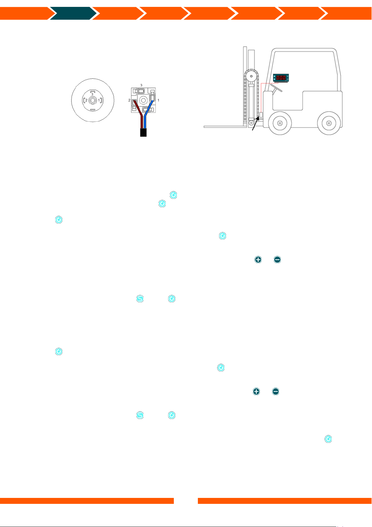
Hydraulic installation on a forklift
The hydraulic sensor is connected as indicated in
this illustration.
The hydraulic transmitter should be placed as close to the lifting cylinder as possible to obtain
the best measuring accuracy.
Setting the Lo calibration point (Kimax 1 Hydraulic)
Raise the forks approx. 20 cm from the ground and lower them again approx. 5 cm.
Enter the menu on the Kimax by pressing for approx. 4 secs (see page 11). Release the
button and the display reads in. Press twice and the display reads Lo.
Press again and the display reads the last saved value for Lo.
In case you want to skip/bypass the Lo calibration, press , now the display reads hi and the
previous value has not been modified.
To change the Lo calibration, you may change the value by pressing or until you have
the value that equals the readout you want when the pressure in the lift cylinder is like the
present pressure.
Example 0.00
You save the value by pressing . Press to continue to hi.
Setting the hi calibration point (Kimax 1 Hydraulic)
Raise the forks approx. 20 cm from the ground with a known weight (the best accuracy is
obtained if the weight is close to the maximum lift capacity) and lower approx. 5 cm again.
Press and now the display reads the last saved value for hi.
In case you want to skip/bypass the hi calibration, press , now the display reads A1 and the
previous value has not been modified.
To change the hi calibration, you may change the value by pressing or until you reach
the value that equals the weight of the load.
You save the value by pressing . Press to continue to A1.
During calibration you can modify Lo and hi in a sequence as described above or you can
modify Lo or hi individually by bypassing the value you do not want to change by pressing
(see page 11).
Brown
Blue
Hydraulic transmitter

9
Introduction
Sensor
installation
Electrical
installation
Setup
Calibration
Protection
Daily use
Additional
information
Electrical installation
Electrical connection
Always disconnect the battery before you perform any installation work on the system of the
vehicle.
Do not route the cables next to ignition cables or other cables carrying large currents.
Make sure that the cables are not exposed to tensile or shearing forces.
Protect the cables with rubber grommets if you route the cables through holes.
For connecting cables use crimp connectors or another approved method.
Avoid short-circuiting the system by faulty connections or squeezed cables.
Fasten the cables at suitable intervals.
Make sure all Kimax 1 instruments are protected with fuses in the supply cables.
Pink RS232 TX Data for a printer
Green RS232 RX Data
Yellow RS232 TX Data
White Relay (A2)
Blue Relay (A2)
Grey Supply 10 - 30 V DC
Brown Ground

10
Introduction
Sensor
installation
Electrical
installation
Setup
Calibration
Protection
Daily use
Additional
information
Optional: Warning light (A2), Tracker and Kimax printer.
Unused wires must be separately isolated.
Fuse
Battery
Switch
Key on
position
Tracker
Warning light
Green
Yellow
White
Grey
Blue
Pink
Brown
Imax 0,5 A
11
Introduction
Sensor
installation
Electrical
installation
Setup
Calibration
Protection
Daily use
Additional
information
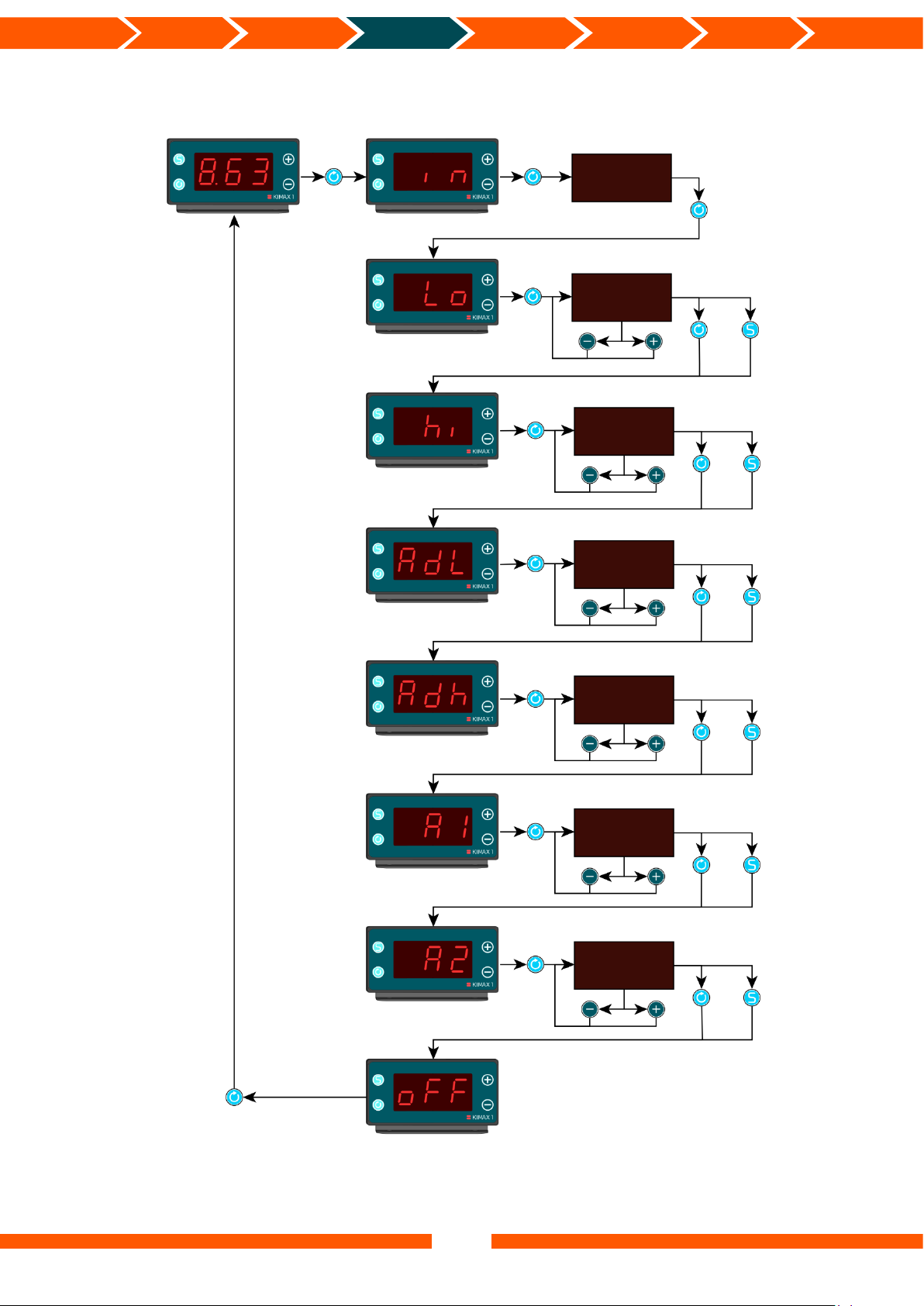
Kimax 1 menu
Press for
~4 secs
Value
Value
Value
Value
Value
Value
Value
Bypass
Bypass
Save value
Bypass
Save value
Bypass
Save value
Bypass
Save value
Bypass
Save value
Bypass
Save value
Adjust the value
Adjust the value
Adjust the value
Adjust the value
Adjust the value
Adjust the value
Back to weight
reading

12
Introduction
Sensor
installation
Electrical
installation
Setup
Calibration
Protection
Daily use
Additional
information
in menu
In the input menu it is possible to read the present signal from the sensor.
A hydraulic transmitter input produces a value ranging from 0 - 100% (0 –22,9 mA).
An air input will give you a reading ranging from 0 - 10,0 bar.
AdL menu
In the AdLmenu it is possible to read the input value of the sensor input from when the Lo
calibration was performed (stored sensor value at empty calibration).
When a Lo calibration is performed the Kimax unit automatically saves the in value from the
sensor input as an AdL value.
Adh menu
In the Adhmenu it is possible to read the input value of the sensor input from when the hi
calibration was performed (stored sensor value at loaded calibration).
When a hi calibration is performed the Kimax unit automatically saves the in value from the
sensor input as an Adh value.
0
2
4
6
8
10
12
14
0 2 4 6 8 10
Tonne
Bar
Calibration Kimax 1 (example)
Calibration
Lo
hi
AdL
Adh
Adh
hi
Lo
AdL
13
Introduction
Sensor
installation
Electrical
installation
Setup
Calibration
Protection
Daily use
Additional
information
Calibration
Two reference values are needed to make a correct calibration, one value for an unloaded
vehicle (Lo), and one for a loaded vehicle (hi). By means of these two reference values the
Kimax 1 Axle Load Indicator will generate a complete pressure chart and display the current
axle load on the display.
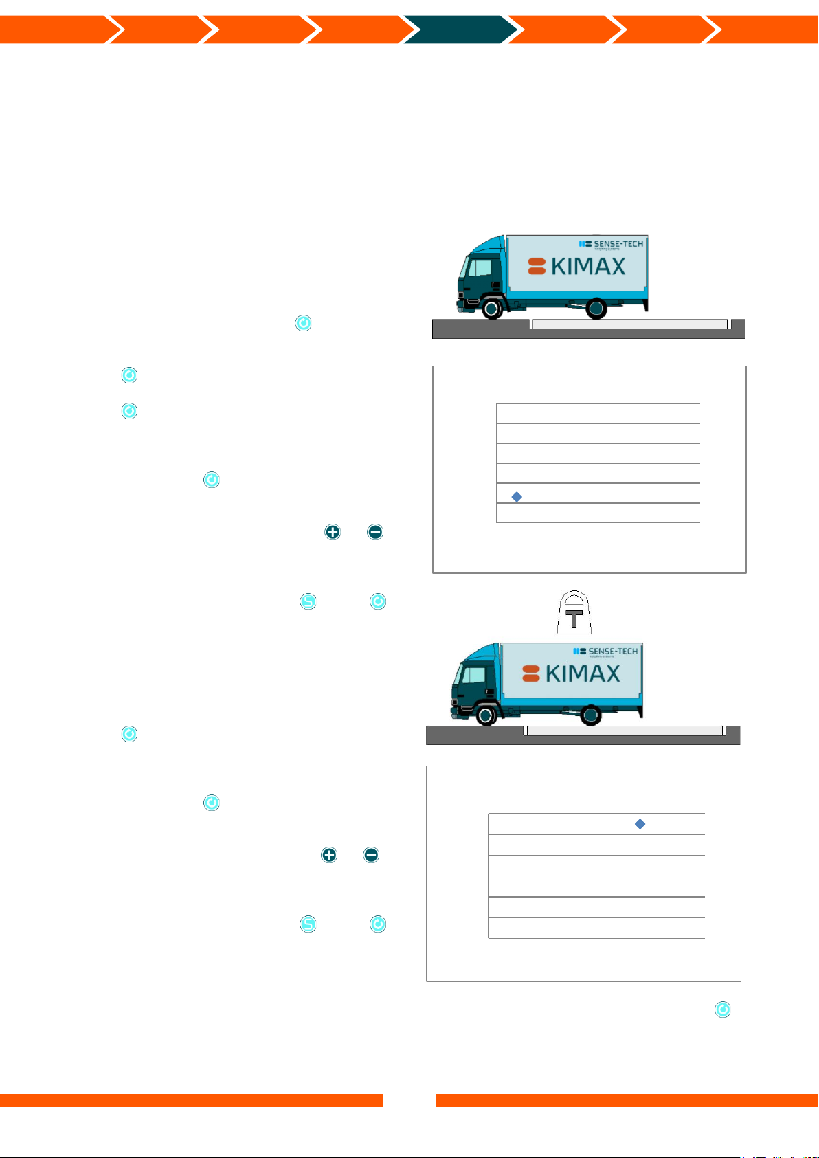
Setting the Lo calibration point
Go to a weighing bridge with your empty
vehicle.
Enter the menu by pressing for approx. 4
secs (see page 11). The display reads in.
Press twice, now the display reads Lo.
Press again and the last saved value for Lo
will be displayed.
In case you want to skip/bypass the Lo
calibration, press , now the display reads hi
and the previous value has not been modified.
To change the Lo calibration press or ,
until you have the value that equals the readout
from the weighing bridge.
You save the value by pressing . Press to
continue to hi.
Setting the hi calibration point
Go to a weighing bridge with your loaded
vehicle.
Press , and the display reads the last saved
value for hi.
In case you want to skip/bypass the hi
calibration, press , now the display reads A1
and the previous value has not been modified.
To change the hi calibration press or
until you have the value that equals the readout
from the weighing bridge.
You save the value by pressing . Press to
continue to A1.
During calibration you can modify Lo and hi in a sequence as described above or you can
modify Lo or hi individually by bypassing the value you do not want to change by pressing
(see page 11).
0
2
4
6
8
10
12
0 5 10
Tonne
Bar
Lo calibration point
0
2
4
6
8
10
12
0 5 10
Tonne
Bar
hi calibration point
Weighing
bridge
Weighing
bridge
14
Introduction
Sensor
installation
Electrical
installation
Setup
Calibration
Protection
Daily use
Additional
information
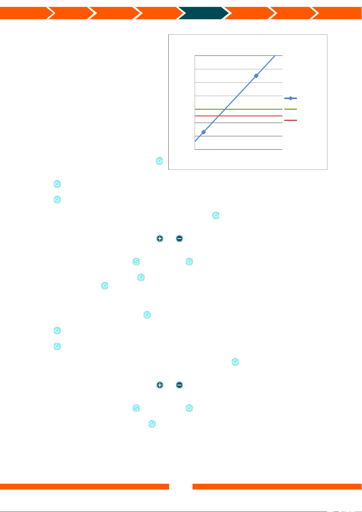
Alarms
The Kimax 1 has two different alarm
functions.
When the weight reading exceeds the A1
alarm level, the three digits in the display
start flashing.
When the weight reading exceeds the A2
alarm level, an internal relay connects
the white and the blue wires in the supply
cable (see page 9-10).
Setting the A1 alarm level
Enter the Kimax menu by pressing
button for 4 sec. (see page 11).
Press button shortly several times until the display reads A1.
Press button once again, and the display reads the last saved A1 value.
In case you want to maintain the previous value, press and the display reads A2 without
saving any modified A1 value.
You can change the value by pressing or until you get a value equal to the alarm level
you want.
You save the value by pressing button, press and the display reads A2.
You leave the menu by pressing shortly several times until the display reads oFF and then
you press the button once more or restart the Kimax.
Setting the A2 alarm level
Enter the Kimax menu by pressing button for 4 sec. (see page 11).
Press button shortly several times until the display reads A2.
Press button once again shortly, and the display reads the last saved A2 value.
In the case you want to maintain the previous value, press and the display reads oFF
without saving any modified A2 value.
You can change the value by pressing or until you get a value equal to the alarm level
you want.
You save the value by pressing button, press and the display reads oFF.
You can leave the menu by pressing or restart the Kimax.
0
2
4
6
8
10
12
14
0 5 10
Tonne
Bar
Calibration Kimax 1 (example)
Calibration
Alarm 2
Alarm 1

15
Introduction
Sensor
installation
Electrical
installation
Setup
Calibration
Protection
Daily use
Additional
information
Protecting your calibration
Locking your Kimax 1
To lock your Kimax 1 and hereby prevent unintended changes to the calibration, activate
and at the same time for 5 seconds, while the Kimax is powered. When the display switches
off you may release the buttons. Now the display reads -L- and the Kimax is locked.
Unlocking your Kimax 1
To unlock the Kimax 1 you must activate and at the same time for 5 seconds, while the
Kimax is powered. When the display switches off you may release the buttons. Now the display
reads -u- and the Kimax is unlocked.

16
Introduction
Sensor
installation
Electrical
installation
Setup
Calibration
Protection
Daily use
Additional
information
Daily use
The Kimax 1 has four buttons and a display with three LED digits. The display is easy to read
in a dark cabin and outside in bright sunlight.
When the unit starts up it shows tot and after 1 sec. the display reads the value of the
currently measured weight of your vehicle/axle/axle group.
If you press the display reads PAY and after 1 sec. the display reads the value of the
payload of your vehicle/axle/axle group. Payload = tot value –Lo value
If you press the button again, the display switches off. Press the button again and you
are back to tot.
The Kimax instrument has a floating point. Values from 0.00 - 9.99 will be displayed with 2
digits after the decimal point. Values from 10.0 - 99.9 will be displayed with 1 digit after the
decimal point. Values from 100 - 999 will be displayed without digits after the decimal point.
Save
Plus
Scroll
Minus
After 1
sec.
After 1
sec.
Back to
tot reading
Power ON

17
Introduction
Sensor
installation
Electrical
installation
Setup
Calibration
Protection
Daily use
Additional
information
Serial output
OBC
The Kimax 1 instrument offers you a RS-232 serial output that broadcasts the measured value,
that you read on the display.
The string of data is broadcasted every 10th second and can be transmitted to a fleet
management vehicle tracker.
To test the serial output, you may set up a ”HyperTerminal” on your laptop with the
parameters below,
Bit pr sec
9.600
Data bit
8
Parity
N
Stopbit
1
Flowcontrol
N
Now you will be able to read the broadcasted value as numeric characters.
You need to set up your fleet management vehicle tracker for receiving data with the same
parameters.
The protocol looks like this:
A XX.X S
Send of message
XX.X actual value
Astart of message
Printer
The Kimax 1 instrument offers you a RS-232 serial output for a printer.
The string of data is broadcasted every time you activate the print function on the instrument,
by pressing for 3 seconds.
As a test, you can set up a ”HyperTerminal” on your laptop with
the parameters shown, and you may read the broadcasted data.
Bit pr sec
4.800
Data bit
8
Parity
N
Stopbit
1
Flowcontrol
N
You need to set up your printer to receive data with the
same parameters.
Most common printers with a serial input can be used
with a Kimax 1 unit.

18
Introduction
Sensor
installation
Electrical
installation
Setup
Calibration
Protection
Daily use
Additional
information
Troubleshooting
Problem
Possible solution
Display is flashing like this...
On
Off
On
Off
The value shown is below zero.
Display is flashing like this...
On
Off
On
Off
When the value on the display exceeds the value for A1
the display starts to flash.
For more information on this function see page 11.
Display is blank
Press the button to turn on the display.
For more information on this function see page 16.
or
Check the wiring see page 9 and 10.
The value shown oscillates..
Check the air hose for leakage.
Make sure the 0,4 mm hole in the throttle is not
blocked.
Check that the AdL and the Adh values are not equal
(see page 12).
Recalibrate the instrument.
The value shown is fixed
Check the air hose for leakage.
Make sure the 0,4 mm hole in the throttle is not
blocked.
Check that the Lo and the hi values are not equal (see
page 12).
Recalibrate the instrument.
Calibration is not possible, the
display shows -L-, when or is
pressed..
The unit is locked/protected from changes made in the
memory.
Check page 15 for unlocking the unit.
If you do not succeed in finding a solution to your issue, feel free to contact us.

19
Introduction
Sensor
installation
Electrical
installation
Setup
Calibration
Protection
Daily use
Additional
information
Dimensions and technical specifications
Kimax 1 cabin version
* Not present on single air inlet instruments
Supply cable
Air inlet
Air inlet*

20
Introduction
Sensor
installation
Electrical
installation
Setup
Calibration
Protection
Daily use
Additional
information
Kimax 1 Trailer version
*The Gore-Tex membrane is for venting the Kimax 1 housing, to avoid getting vacuum in the
housing during shifting ambient temperatures.
The Gore-Tex membrane is only present on the trailer versions of the Kimax 1 instruments.
If you paint the instrument, make sure the venting opening in the Gore-Tex membrane is not
blocked with paint, cover it with painter’s tape before painting.
** Not present on single air inlet instruments. On single air inlet instruments the Gore-Tex
membrane is placed here.
Air inlet
Air inlet**
Supply cable
Gore-Tex Membrane*
Table of contents


