A-OM
A-BUS®Output Module
Instruction Manual
Product Overview
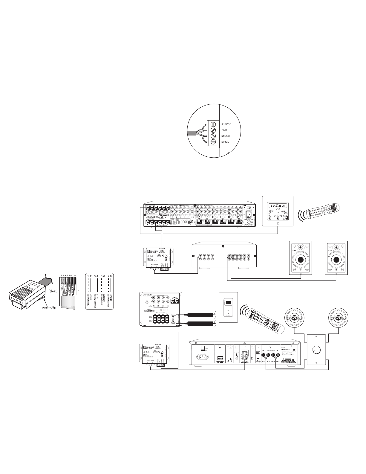
The Russound A-OM A-BUS Output Module provides a
fixed-level stereo line output from an A-BUS keypad
port on any A-BUS hub or other A-BUS-ready multi-
room system. This is useful for sending fixed-level
audio signals to an external amplifier or receiver for
amplification.
The module can be located with the system controller
or hub, or remotely with the amplifier or receiver. It
connects to the A-BUS port with a single CAT-5 cable
and provides RCA jacks for the audio output.
The A-OM also provides connections for an infrared
receiver so the source equipment can be operated
from the zone by an IR remote control.
Features
• Provides fixed-level stereo line output
• Works with any standard A-BUS keypad port
• Includes IR receiver input terminals
• Compact chassis mounts on any surface
5 Forbes Road, Newmarket NH 03857 USA
Tel 603.659.5170 • Fax 603.659.5388
www.russound.com
Warranty
The Russound A-OM is fully guaranteed against all defects in materials and
workmanship for two (2) years from the date of purchase. During this period,
Russound will replace any defective parts and correct any defect in workman-
ship without charge for either parts or labor.
For this warranty to apply, the unit must be installed and used according to its
written instructions. If service is necessary, it must be performed by
Russound. The unit must be returned to Russound at the owner's expense and
with prior written permission. Accidental damage and shipping damage are not
considered defects, nor is damage resulting from abuse or from servicing by
an agency or person not specifically authorized in writing by Russound.
This warranty does not cover: damage caused by abuse, accident, misuse,
negligence, or improper installation or operation; power surges and lightning
strikes; normal wear and maintenance; products that have been altered or
modified; any product whose identifying number, decal, serial number, etc. has
been altered, defaced or removed.
Russound sells products only through authorized dealers and distributors to
ensure that customers obtain proper support and service. Any Russound prod-
uct purchased from an unauthorized dealer or other source, including retailers,
mail order sellers and online sellers will not be honored or serviced under exist-
ing Russound warranty policy. Any sale of products by an unauthorized source
or other manner not authorized by Russound shall void the warranty on the
applicable product.
Damage to or destruction of components due to application of excessive
power voids the warranty on those parts. In these cases, repairs will be made
on the basis or the retail value of the parts and labor. To return for repairs, the
unit must be shipped to Russound at the owner's expense, along with a note
explaining the nature of service required. Be sure to pack the unit in a corru-
gated container with at least three (3) inches of resilient material to protect the
unit from damage in transit.
Before returning a unit for repair, call Russound at 603.659.5170 for a return
authorization number. Write this number on the shipping label and ship to:
Russound, 5 Forbes Road, Newmarket, NH 03857.
Specifications
Input connector: RJ-45 8-pole modular jack
Output connectors: (2) RCA jacks, left and right audio
IR receiver connector: Removable 4-pole screw terminal
Input power (via CAT-5): 24 VDC 200 mA
IR receiver power: 12 VDC 200 mA maximum
Mounting method: Surface
Finish: Black
Dimensions: 3.33” W x 2.38” H x 1.59” D
(8.4 x 6.0 x 4.0 cm)
Weight: 5.6 oz (158 g)
Safety Instructions
1. Read these instructions.
2. Keep these instructions.
3. Heed all warnings.
4. Follow all instructions.
5. Do not use this apparatus near water.
6. Clean only with dry cloth.
7. Do not block any ventilation openings. Install in accor-
dance with the manufacturer’s instructions.
8. Do not install near any heat sources such as radiators,
heat registers, stoves, or other apparatus (including
amplifiers) that produce heat.
9. Do not defeat the safety purpose of the polarized or
grounding plug. A polarized plug has two blades with
one wider than the other. A grounding plug has two
blades and a third grounding prong. The wide blade or
the third prong is provided for your safety. If the provid-
ed plug does not fit into your outlet, consult an electri-
cian for replacement of the obsolete outlet.
10. Protect the power cord from being walked on or
pinched, particularly at plugs, convenience receptacles,
and the point where it exits from the apparatus.
11. Use only attachments or accessories specified by the
manufacturer.
12.Use only with the cart, stand, tripod, bracket, or table
specified by the manufacturer or sold with the appara-
tus. When a cart is used, use caution when moving the
cart-apparatus combination to avoid injury from tip-over.
13.Unplug this apparatus during lightning storms or when
unused for long periods of time.
14.Refer all servicing to qualified service personnel.
Servicing is required when the apparatus has been dam-
aged in any way, such as the power supply cord or plug
is damaged, liquid has been spilled or objects have fall-
en into the apparatus, or the apparatus has been
exposed to rain or moisture, does not operate normally,
or has been dropped.
If you have any questions, call Russound at
1.800.638.8055 or 603.659.5170.
Copyright © 2006 Russound. All rights reserved. All trademarks are the
property of their respective owners. Specifications are subject to change with-
out notice. Russound is not responsible for typographical errors or omissions.
28-1244 04/27/06
A-BUS is a registered trademark of LeisureTech Electronics Pty Ltd Australia.