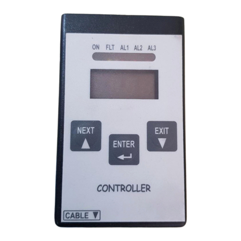
Sensitron STS/CKD+ User manual

Manuale d’istruzione / Instruction Manual
MT4508 rev.0 01/10/2020©
2020 SENSITRON S.R.L. - All rights reserved - www. sensitron.it
Tastierino di calibrazione / Calibration keypad
STS/CKD+

THIS MANUAL MUST BE CAREFULLY READ BY ALL PERSONS WHO HAVE OR
WILL HAVE THE RESPONSIBILITY FOR INSTALLING, USING OR SERVICING
THIS PRODUCT.
Like any equipment, this product will perform as designed only if installed,
used and serviced in accordance with the manufacturer’s instructions.
OTHERWISE, IT COULD FAIL TO PERFORM AS DESIGNED AND PERSONS
WHO RELY ON THIS PRODUCT FOR THEIR SAFETY COULD SUFFER SEVERE
PERSONAL INJURY OR DEATH.
The warranties made by Sensitron s.r.l. with respect to this product are voi-
ded if the product is not installed, used and serviced in accordance with
the instructions in this user guide. Please protect yourself and others by
following them.
We recommend our customers to write or call us regarding this equipment
prior to use or for any additional information relative to use or repair.
QUESTO MANUALE DEVE ESSERE LETTO ATTENTAMENTE DATUTTI COLORO
CHE HANNO O AVRANNO LA RESPONSABILITA’ DI INSTALLARE, UTILIZZARE
O DI PRESTARE UN SERVIZIO DI ASSISTENZA SU QUESTO PRODOTTO.
Come ogni componente di un sistema, questo prodotto funzionerà corret-
tamente solo se installato, utilizzato e controllato come prescritto dal fab-
bricante.
IN CASO CONTRARIO, POTREBBE NON FUNZIONARE CORRETTAMENTE E LE
PERSONE CHE AFFIDANO LA LORO SICUREZZA A QUESTO PRODOTTO PO-
TREBBERO SUBIRE DANNI PERSONALI O LETALI.
La garanzia riconosciuta da Sensitron s.r.l. su questo prodotto potrebbe es-
sere nulla se il prodotto non venisse installato, utilizzato e controllato se-
condo le istruzioni fornite con il presente manuale. Per favore, proteggetevi
seguendole attentamente.
Invitiamo i nostri clienti a scriverci o a chiamarci per ogni informazione ri-
guardo questo strumento, il suo uso o una sua eventuale riparazione.

ItalianoEnglish
SUMMARY
1. Introduction..................................................................................................... 9
1.1 Description ...........................................................................................................................9
2. Connection and autotest............................................................................ 10
3. Menu .................................................................................................................. 11
4. Menu diagrams............................................................................................... 13
4.1 Menu diagrams ...................................................................................................................13
4.2 Operating errors...................................................................................................................15
5. Troubleshoot of detector’s errors ............................................................ 15
6. Warranty............................................................................................................ 16
7. Instructions for disposal.............................................................................. 16
SOMMARIO
1. Introduzione.................................................................................................... 1
1.1 Descrizione generale..........................................................................................................1
2. Connessione e autotest............................................................................... 2
3. Menu .................................................................................................................. 3
4. Schemi di funzionamento .......................................................................... 5
4.1 Schemi di funzionamento................................................................................................5
4.2 Errori di utilizzo.....................................................................................................................7
5. Risoluzione dei problemi del rilevatore................................................. 7
6. Garanzia ............................................................................................................ 8
7. Istruzioni per lo smaltimento .................................................................... 8

ITALIANO
Pag. 1
1. Introduzione
1.1 Descrizione generale
IIl nuovo tastierino di calibrazione STS/CKD+ si adatta a tutti i rivelatori gas prodotti da Sen-
sitron s.r.l. La tastiera di calibrazione è fornita con un adattatore per la connessione ai rileva-
tori della serie SMART P.
La tastiera di calibrazione permette di eseguire*:
³Taratura di Zero;
³Taratura dello Span;
³Taratura dell’uscita 4-20 mA;
³Modica delle soglie di allarme e della relativa isteresi;
³Reset del dispositivo;
³”Head pairing”(accoppiamento del rivelatore con la testa sensore) ;
³Modica o sola visualizzazione del Baud Rate;
³Impostazione dell’indirizzo del bus RS485;
³Visualizzazione della versione del rmware del rivelatore.
*Le voci elencate dipendono dalla tipologia di rilevatore collegato, riferirsi alla Tabella 3 per
eventuali chiarimenti.
La tastiera di calibrazione può essere collegata a rivelatore sia spento che acceso. Prima di
aprire il coperchio del rilevatore, assicurarsi di aver preso le precauzioni di sicurezza neces-
sarie.
Per il collegamento della tastiera fare riferimento al capitolo seguente.

ITALIANO
Pag. 2
2. Connessione e autotest
Per collegare il tastierino di calibrazione occorre innanzitutto aprire il rilevatore, consideran-
do le adeguate misure di sicurezza, e collegare il cavo del tastierino all’apposito connettore.
Nel caso, consultare il manuale del rilevatore con lo specico schema topograco del cir-
cuito. Se il rilevatore è uno SMART P, occorre collegare il tastierino allo specico adattatore
riportato in Figura 1 (fornito con il tastierino STS/CKD+).
Figura 1) Adattatore per rilevatori SMART P
Se si collega il tastierino mentre il rilevatore è in warm-up, compare la scritta HEAT e tutti i
LED si accendono. Quando il rilevatore esce dalla fase di warm-up, la scritta HEAT scompare
e rimane acceso solo il LED“ON”.
Una volta collegato, il tastierino eseguirà un autotest interno. Questo passaggio permette
di rendere noti eventuali malfunzionamenti della tastiera di calibrazione. Se è presente un
malfunzionamento, viene visualizzato il relativo errore.
Gli errori che possono essere visualizzati sono:
Tabella 1) Errori successivi alla fase di autotest del tastierino
Errore visualizzato Descrizione
ArAn La memoria RAM del tastierino pre-
senta un’anomalia
AFLS La memoria Flash del tastierino è cor-
rotta
Arr Errore generico
Nel caso in cui venga riportato uno di questi errori, l’operatore può solo provare a scollegare
e ricollegare nuovamente la tastiera di calibrazione. Se l’errore persiste, contattare l’assisten-
za Sensitron.

ITALIANO
Pag. 3
3. Menu
Il tastierino di calibrazione presenta un menù con diverse voci, ognuna delle quali permette
di condurre un’azione diversa sul rivelatore. Nella tabella di seguito sono riportate tutte le
possibili voci presenti.
vimento.
Tabella 2) Descrizione delle voci presenti nel menù del tastieirno
Nome
vissualizzato
Signicato Descrizione
PSd Password 1234. Permette di accedere alle voci del menù del tastierino.
Se non viene inserita, l’utente può solo eseguire il reset o vi-
sualizzare la versione rmware del rilevatore.
Se si vuole modicare le soglie di allarme e il valore di istere-
si, la password da inserire è 5345.
Zero Zero Quando il rilevatore viene acceso per la prima volta o quando
un nuovo elemento sensibile viene montato, si raccomanda
di eseguire la taratura di ZERO.
Quest’operazione deve essere eseguita con il rilevatore nelle
seguenti due condizioni:
- Il rilevatore deve trovarsi in aria pulita cioè in assenza di so-
stanze interferenti.
- Il rivelatore deve essere acceso da almeno 8 ore.
Span Span La taratura dello Span permette la modica della sensibilità
al gas del rilevatore.
Per la calibrazione dello Span (sensibilità al gas) è richiesta
una bombola di gas campione.
Se la concentrazione di gas della bombola campione è di-
versa da quella visualizzata sul tastierino, allora si deve ef-
fettuare la calibrazione dello Span. In caso contrario questa
operazione non è necessaria.
Per la corretta taratura dei rivelatori, Sensitron ha realizzato
una VALIGETTA TEST che contiene tutta la strumentazione
necessaria per eseguire le prove di funzionalità richieste.
Il KIT di calibrazione fornito con la valigia contiene il neces-
sario per vericare in campo la risposta al gas dei rilevato-
ri Sensitron. Il cappuccio di calibrazione ha la possibilità di
adattarsi a tutte le teste di rilevazione prodotte utilizzando,
se necessario, i riduttori presenti nel kit.
La valvola per bombola con ussometro permette di erogare
il gas di prova ad una portata tale da ottenere dati veritieri
riguardo allo stato di salute dell’elemento sensibile.
t4.20 Taratura
4-20
Taratura uscita 4-20 mA.
THr1 Threshold 1 Visualizza e permette la modica della soglia di allarme 1
THr2 Threshold 2 Visualizza e permette la modica della soglia di allarme 2

ITALIANO
Pag. 4
Nome
vissualizzato
Signicato Descrizione
THr3 Threshold 3 Visualizza e permette la modica della soglia di allarme 3
HYSt Hysteresis Visualizza e permette la modica dell’isteresi delle soglie di
allarme
rES Reset Permette di resettare il rivelatore
PAIr Pairing Eettua l’accoppiamento dell’elemento sensibile con il rive-
latore
VEr Version Versione del rmware del rilevatore
Adr Address Visualizza e permette la modica dell’indirizzo RS485 del ri-
velatore
bAUd Baudrate Visualizza e permette la modica del baud-rate della porta
seriale.
Lista valori disponibili: 9600, 115200.
A seconda della tipologia di rivelatore scelto, saranno poi disponibili solo alcune voci del
menu di calibrazione. Le voci disponibili per ogni classe di rilevatore sono elencate nella
tabella sottostante.
Tabella 3) Voci del menu disponibili per ogni tipologia di rilevatori SMART
SOTTO-MENU Tipologia rivelatore SMART
3G 3R 3H Serie LITE P S
Password Richiesta per tutti i dispositivi all’ingresso. Per tutti la password è 1234.
Zero Presente in tutti dispositivi, se almeno un sensore è collegato
Span Presente in tutti dispositivi, se almeno un sensore è collegato
4-20 mA x
Thr1 x
Thr2 x x x x x x
Thr3 x x x x x x
Hysteresis x x x x x x
Reset x x x x x x
Pairing x x
Version x x x x x x
Address x[2] x x x x x
Baudrate Solo
visualizzato[2]
x x x Solo
visualizzato
x
[1] Per modicare le soglie di allarme e il valore di isteresi occorre entrare nel menù con la
password 5345.
[2] Per le precedenti versioni di SMART 3G, la visualizzazione e/o modica dell’indirizzo e del
baudrate non è possibile.

ITALIANO
Pag. 5
ENTER
ESC
ENTER
*
ENTER
ENTER
ESC
ENTER
*
ENTER
ENTER
ESC
ENTER
*
ENTER
ENTER
ESC
Valore di “span” confermato
ENTER
ESC
ENTER
ESC
Concentrazione attuale
ENTERENTER
ESC
ENTER
Concentrazione bombola di gas
*
ENTER
ESC
ENTER
ENTER
ESC
Valore di “zero” confermato
ENTER
ESC
ENTER
ESC
“Zero” Attuale
ENTER
“Zero”per O2 è ‘20.9’
per altri gas è ‘0’.
*
ENTER
ESC
ENTER
ENTER
“PWd
OK”
La cifra in modifica è lampeggiante.
* Set Value
Set
Digit
Set
Digit
ENTER
Set
Digit
ENTER
Set
Digit
ENTER
ENTER
ESCESCESC
ESC
ENTER
*
ENTERENTER
Start
ENTER
ESC
ENTER ENTER
ESC
4. Schemi di funzionamento
4.1 Schemi di funzionamento
La procedura di taratura dello zero per i rilevatori della serie “Smart 3G” non prevede il set-
taggio del livello di zero (ragurato come ZGL – Zero Gas Level). La lettura in punti attuale
viene considerata come nuovo valore di zero.
Impostazione soglie di allarme,
solo tramite password 5345

ITALIANO
Pag. 6
ENTER
*
ENTER
ENTER
*
ENTER
ENTER
ESC
ENTER
Start
ENTERENTER
Start
ENTERENTER
La cifra in modifica è lampeggiante.
* Set Value
Set
Digit
Set
Digit
ENTER
Set
Digit
ENTER
Set
Digit
ENTER
ENTER
ESCESCESC
ESC
ENTER
ESC
ENTER
ESC
ENTER
ESC
ENTER
*
ENTER

ITALIANO
Pag. 7
4.2 Errori di utilizzo
Tabella 4) Tipologie di errori che si possono vericare durante l’utilizzo
Tipologia di errore Possibile causa Azione conseguente
Errore di calibrazione
(ErrC)
Lettura del sensore fuori
range
Non viene eettuata la
taratura
Warning di taratura dello zero
(UnG0 – Warning invalid zero)
Lettura del sensore dif-
ferente dal valore di zero
atteso
La taratura viene eet-
tuata ma con un messag-
gio di avviso
Warning di taratura dello span
(UnGS – Warning invalid sensitivity)
Lettura del sensore dif-
ferente dal valore di
span atteso
La taratura viene eet-
tuata ma con un messag-
gio di avviso
Errore di impostazione della soglia
(ErrT)
Inserimento di un valore
fuori range
Non viene memorizzata
la soglia inserita
Errore di impostazione del valore di
isteresi
(ErrT)
Inserimento di un valore
fuori range
Non viene memorizzato il
valore inserito
Errore di impostazione dell’indirizzo
(ErrA)
Inserimento di un valo-
re fuori range (range: 1-
247)
Non viene memorizzato
l’indirizzo inserito
Errore di impostazione del baudrate
(ErrB)
Inserimento di un valo-
re non ammesso (possi-
bili valori: 9600, 19200,
38400, 115200)
Non viene memorizzato il
valore inserito
5. Risoluzione dei problemi del rilevatore
Tabella 5) Risoluzione dei problemi del rilevatore
Problema Possibile causa Rimedio
Messaggio
UEOL sul display
Termine tempo vita sensore Necessità di cambiare il sensore
Messaggio:
“ErrH”
Mismatch tra testa e rilevatore Eseguire il pairing tra testa e rilevatore
Messaggio Untn
sul display
Scadenza tempo di manutenzione
del sensore
Necessità di vericare la funzionalità del
sensore
Messaggio EE2P
sul display
La memoria interna E2Prom del ri-
velatore presenta un’anomalia
Eettuare l’operazione di reset mediante
il codice di accesso 459
Messaggio EFLS
sul display
La memoria interna Flash del rive-
latore presenta un’anomalia
Eettuare l’operazione di reset mediante
il codice di accesso 459
Messaggio ErAN
sul display
La memoria interna RAM del rive-
latore presenta un’anomalia
Eettuare l’operazione di reset mediante
il codice di accesso 459
Messaggio
EALM sul display
L’alimentazione del rivelatore è
fuori dai range prescritti
Controllare l’alimentazione sui morsetti
+ e – del rivelatore

ITALIANO
Pag. 8
6. Garanzia
La garanzia sui prodotti Sensitron è valida un anno dalla data di fabbricazione riportata sul
prodotto.
7. Istruzioni per lo smaltimento
Quando il dispositivo raggiunge la ne della sua vita utile, deve essere smaltito in conformi-
tà con i requisiti locali di gestione dei riuti e la legislazione ambientale.
I materiali utilizzati si possono dividere nelle seguenti categorie:
³Scatola del tastierino: Plastica
³Base board: Riuti di apparecchiature elettriche e elettroniche (RAEE)
In alternativa, il vecchio dispositivo può essere imballato in modo sicuro, chiaramente con-
trassegnato per lo smaltimento ambientale e restituito a Sensitron.
Sensitron ha una politica di continuo sviluppo e miglioramento dei suoi prodotti. Pertanto, le speciche del
dispositivo descritte in questo documento possono essere modicate senza preavviso. In caso di modica del
prodotto, Sensitron declina ogni responsabilità. I dati possono cambiare, così come la legislazione e si consiglia
vivamente di ottenere copie delle più recenti normative, standard e linee guida emesse. Questa pubblicazione
non intende costituire la base di un contratto. Nessuna parte di questa pubblicazione può essere riprodotta,
distribuita o trasmessa in qualsiasi forma o con qualsiasi mezzo, inclusi fotocopie, registrazioni o altri metodi
elettronici o meccanici, senza la previa autorizzazione scritta di Sensitron.
Problema Possibile causa Rimedio
Messaggio EI2C
sul display
Non c’è comunicazione fra la testa
sensibile e la base
Controllare che il rivelatore non sia in-
stallato in ambienti con temperature di
lavoro superiori ai 60°C, spostare even-
tualmente il rivelatore. Se il problema
persiste sostituire la testa sensibile con
una nuova.
Messaggio EAnP
sul display
La base base dello SMART non ri-
conosce il serial number della te-
sta sensibile ad essa collegata e
questo può dipendere dal fatto
che le teste fra due rivelatori sono
state invertite.
Controllare che il serial number della te-
sta sia lo stesso riportato sull’etichetta
del serial number sul rivelatore.
Messaggio E420
sul display
Loop 4-20 interrotto Ripristinare il loop 4-20
Messaggio EAdc
sul display
Errore lettura segnale proveniente
dal sensore
Spegnere e riaccendere il rilevatore. Nel
caso in cui l’errore persisita, contattare
Sensitron srl.
Messaggio EBCH
sul display
I dip-switch (1 & 8) per il ripristino
dati a default sono in posizione
sbagliata
Riportare I dip-switch in posizione cor-
retta seguendo le istruzioni riportate nel
manuale tecnico del rivelatore

ENGLISH
Pag. 9
1. Introduction
1.1 Description
The calibration keypad STG can be used for all the gas detectors of Sensitron s.r.l.
The calibration keypad is supplied with an adapter for connection to SMART P detectors.
The calibration keypad enables the following*:
³Zero calibration;
³Span calibration;
³4-20 ma output calibration;
³To change the alarm thresholds and its hysteresis;
³To reset the device;
³To couple detector with the sensor head “Head pairing”;
³To change or visualize only the Baud Rate;
³To set the address of the RS485 bus;
³To show the rmware version of the detector;
* The mentioned operations are function of the gas detector in use, see Table 3 for further
clarications.
The keypad can be connected both when the detector is powered on and operating and
when the detector is o. Before opening the detector enclosure, be sure that all safety pre-
cautions have been considered.
To connect the keypad, refer to the following chapter.

ENGLISH
Pag. 10
2. Connection and autotest
To connect the calibration keypad to the gas detector, the user has to open the detector,
following the safety instructions, and locate the connection for the keypad. Please refer to
the technical manual of the gas detector to be sure of the connection position.
Gas detectors of SMART P series require a specic connector adapter to connect the calibra-
tion keypad. The adapter is shown in Figure 1 and it’s supplied with the calibration keypad.
Figure 1) SMART P connector adapter
If the user connects the keypad while the detector is warming-up, the HEAT message appe-
ars and all the LEDs light up. When the warm-up phase ends, the HEAT message disappears
and only the“ON”LED remains on.
Once connected, the calibration keypad will execute an autotest. This procedure allows to
detect possible internal errors. If an failure occurs, the error name will be displayed.
The possible errors are:
Table 1) Possible errors visualised after the autotest process
If one of the described errors occurs, the user can only disconnect and connect again the
calibration keypad. If the error is still present, please contact the Sensitron assistance.
Displayed error Description
ArAn The internal RAM memory is not wor-
king
AFLS The internal Flash memory is not wor-
king
Arr General error

ENGLISH
Pag. 11
3. Menu
The calibration keypad has a menu with several options, each one of them allows to per-
form dierent actions on the detector. In the following table are summarised all the possible
actions.
Table 2) Calibration keypad menu description
Displayed
name
Meaning Description
PSd Password 1234. It allows to access the keypad menu, otherwise the user
can only reset the detector or visualise its rmware version.
To modify the alarm thresholds and the hysteresis value, the
password is 5345.
ZEro Zero When the detector is turned on for the rst time, or when
a new kit sensor head is mounted into the instrument, the
ZERO calibration is recommended.
This action has to be done under the following two condi-
tions:
-The detector is to be in fresh air (without any gas or interfe-
ring compounds);
-it must be powered on at least for 8 hours.
Span Span The Span allows the instrument calibration and is to be exe-
cuted if the response in gas of the instrument is not correct.
To run the Span calibration, it is essential the use of a sample
gas bottle with Target Gas.
If the concentration of the sample gas bottle is dierent from
that displayed on the keypad, then must be performed the
Span calibration. Otherwise this step is not necessary.
For the correct calibration of gas detectors, Sensitron makes
available a dedicated calibration case complete with all ne-
cessary tools to perform accurate tests. The calibration KIT,
supplied with a carrying case, comprises the necessary in-
strumentation to verify in situ the response of Sensitron's
gas detectors.
The calibration cap can be tted on all of Sensitron sensing
heads by employing, when necessary, the endowed adap-
tors. Both gaskets and screw threads inside the cap allow an
optimum tightness between the sensing head and the cap.
The analysis chamber inside the calibration cap has been de-
signed and realized to obtain a test method identical to the
one adopted in our Laboratory for the initial factory calibra-
tion. The ow meter valve is to be mounted on the gas can
to allow the gas ow at a controlled velocity to obtain accu-
rate data to verify the sensing element status.
t4.20 4-20 cali-
bration
4-20 mA output calibration

ENGLISH
Pag. 12
Displayed
name
Meaning Description
THr1 Threshold 1 Displays and allows editing of the rst alarm threshold
THr2 Threshold 2 Displays and allows editing of the second alarm threshold
THr3 Threshold 3 Displays and allows editing of the third alarm threshold
HYSt Hysteresis Displays and allows editing of hysteresis of the alarm thre-
sholds
rES Reset Reset of the Fault status
PAIr Pairing It allows the pairing between the sensing element and the
detector
VEr Version Detector rmware version
Adr Address To display and set the detectors’address on the RS485 bus
bAUd Baudrate Displays and allows editing of the baud rate of the serial port.
List of available values: 9600, 115200
Depending on the detectors’series, dierent menu entries are available. The following table
reports the available items per each type of detector
Table 3) Menu component available per each detector of SMART series
SUB-MENO SMART series
3G 3R 3H Serie LITE P S
Password Always requested at the start, the password is 1234 for all the gas detec-
tors.
Zero Available for all detectors, if at least one sensor is connected
Span Available for all detectors, if at least one sensor is connected
4-20 mA x
Thr1 x
Thr2 x x x x x x
Thr3 x x x x x x
Hysteresis x x x x x x
Reset x x x x x x
Pairing x x
Version x x x x x x
Address x[2] x x x x x
Baudrate Visualised
only[2]
x x x Visualised
only
x
[1] To modify the alarm thresholds and the hysteresis value, the menu password is 5345.
[2] For old SMART 3G versions, the address and the baudrate options are not present.

ENGLISH
Pag. 13
4. Menu diagrams
4.1 Menu diagrams
Confirmed “span” value
Actual gas concentration
Gas tank concentration
Confirmed “zero” value
Actual “zero”
“Zero” for O2 is ‘20.9’
for the other gases is ‘0’.
The digit blinks when the user edits it
* Set Value
Set
Digit
Set
Digit
ENTER
Set
Digit
ENTER
Set
Digit
ENTER
ENTER
ESCESCESC
ESC
ENTER
ESC
ENTER
*
ENTER
ENTER
ESC
ENTER
*
ENTER
ENTER
ESC
ENTER
*
ENTER
ENTER
ESC
ENTER
ESC
ENTER
ESC
ENTERENTER
ESC
ENTER
*
ENTER
ESC
ENTER
ENTER
ESC
ENTER
ESC
ENTER
ESC
ENTER
*
ENTER
ESC
ENTER
ENTER
“PWd OK”
ENTER
*
ENTERENTER
Start
ENTER
ESC
ENTER ENTER
ESC
Zero calibratrion for gas detectors of“Smart 3G”series has not the setting of a zero level (re-
ported as ZGL -Zero Gas Level). The actual reading is considered as new zero value.
Settings of alarm thresholds,
only by password 5345.

ENGLISH
Pag. 14
* Set Value
Set
Digit
Set
Digit
ENTER
Set
Digit
ENTER
Set
Digit
ENTER
ENTER
ESCESCESC
ESC
The digit blinks when the user edits it
ENTER
*
ENTER
ENTER
*
ENTER
ENTER
ESC
ENTER
Start
ENTERENTER
Start
ENTERENTER
ENTER
ESC
ENTER
ESC
ENTER
ESC
ENTER
*
ENTER

ENGLISH
Pag. 15
4.2 Operating errors
Table 4) Posible kind of errors that can occur during operations with the calibration keypad
Tipologia di errore Possibile causa Azione conseguente
Calibration error
(ErrC)
Sensor’s reading out of ran-
ge
The zero calibration is not
performed
Zero calibration warning
(Ung0 – warning invalid zero)
The sensor has a non-zero
reading
The zero calibration is per-
formed but with a warning
notice
Span calibration warning
(Ung0 – warning invalid sensiti-
vity)
The user has set a span va-
lue out of range
The span calibration is per-
formed but with a warning
notice
Threshold setting error (ErrT) The user has set a threshold
out of range
The threshold is not me-
morised
Hysteresis setting error (ErrT) The user has set a hystere-
sis value out of range
The hysteresis is not me-
morised
Address error (ErrA) The user has set a value out
of range (range: 1- 247)
The address is not memo-
rised
Baudrate error (ErrB) The user has set a non-ad-
missible value (admissible
values: 9600, 19200, 38400,
115200)
The baudrate value is not
memorised
5. Troubleshoot of detector’s errors
Table 5) Troubleshooting
Problem Possible causes Remedies
UEOL message End of sensor lifetime Sensor substitution
“ErrH”message Mismatch between the head and
the gas detector
Please perform pairing procedure
Untn message Due date sensor maintenance Check sensor functionality (with a
gas test, for example)
EE2P message The internal memory E2Prom is
not working
Please perform the reset procedure
by the 459 tech password
EFLS message The internal memory Flash is not
working
Please perform the reset procedure
by the 459 tech password
ErAN message The internal memory Ram is not
working
Please perform the reset procedure
by the 459 tech password
EALM message The power supply of the detector
is outside of range (from 12Vdc to
24Vdc)
Please check the power supply on
the + and – terminals of the detector

ENGLISH
Pag. 16
Problem Possible causes Remedies
EI2C message There is no communication
between the sensor head and
the microprocessor base board of
SMART 3
Please check that the detector is
not installed in environments with a
temperature over 60 ° C. If so, chan-
ge the detector installation position.
If the problem is still present replace
the sensor head with a new one.
EAnP message The SMART3 detector main board
does not match the sensor head
connected (doesn’t match the se-
rial number inside). May be that
the heads between two dierent
detectors are inverted.
Check that the serial number prin-
ted on the sensor head it is the same
that the one printed on the detector
label.
E420 message Interrupted 4-20 loop Restore 4-20 loop
EAdc message Error while reading sensor signal Restart the gas detector. If the error
still occurs, contact Sensitron s.r.l
EBCH message The dip switches (1 & 8) for the
data recovery of the detector are
in the wrong position
Please set the dip switches for data
recovery in the right position, fol-
lowing the technical manual.
6. Warranty
Warranty on Sensitron products is valid one year from the manufacturing date placed on the
product.
7. Instructions for disposal
When the device reaches the end of its life, it should be disposed of in accordance with local
waste management requirements and environmental legislation.
Employed materials are subdivided into the following categories:
³Keypad enclosure: Plastic
³Base board: Waste Electrical & Electronic Equipment (WEEE)
Alternatively, the old device may be securely packaged, clearly marked for environmental
disposal and returned to Sensitron.
Sensitron has a policy of continuous development and improvement of its products. As such the specication
for the device outlined in this document may be changed without notice. In case of modication of the pro-
duct, Sensitron disclaims all liability. Data may change, as well as legislation and you are strongly advised to
obtain copies of the most recently issued regulations, standards and guidelines. This publication is not inten-
ded to form the basis of a contract. No part of this publication may be reproduced, distributed, or transmitted
in any form or by any means, including photocopying, recording, or other electronic or mechanical methods,
without the prior written permission of Sensitron.

Contact details: SENSITRON s.r.l. Viale della Repubblica, 48 - 20007 - Cornaredo (MI) Italy
LEADER IN SIL2 (SIL3) FIXED GAS DETECTION SYSTEMS
Table of contents
Languages:
Other Sensitron Keypad manuals
