manuals.online logo
Brands
  1. Home
  2. •
  3. Brands
  4. •
  5. Contro l4
  6. •
  7. Keypad
  8. •
  9. Contro l4 C4-SKCB2 User manual

Contro l4 C4-SKCB2 User manual

Square Wired
Configurable Keypad V2
Installation Guide
Introduction
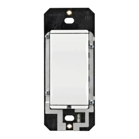
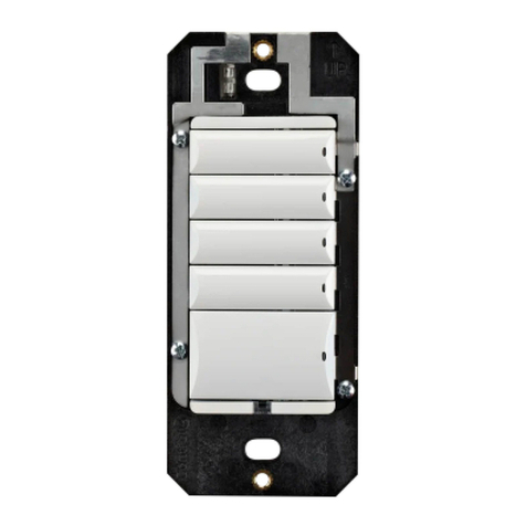
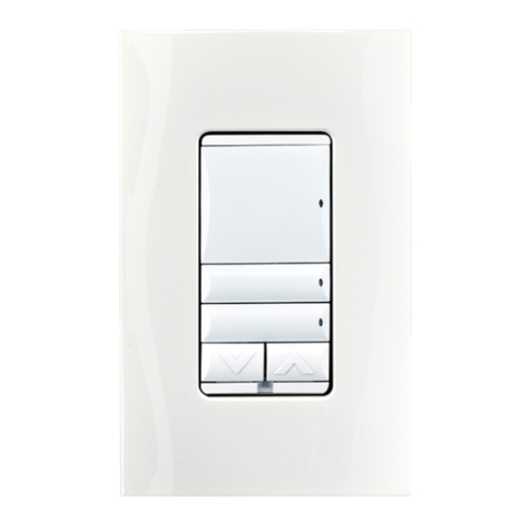
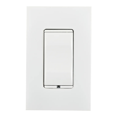
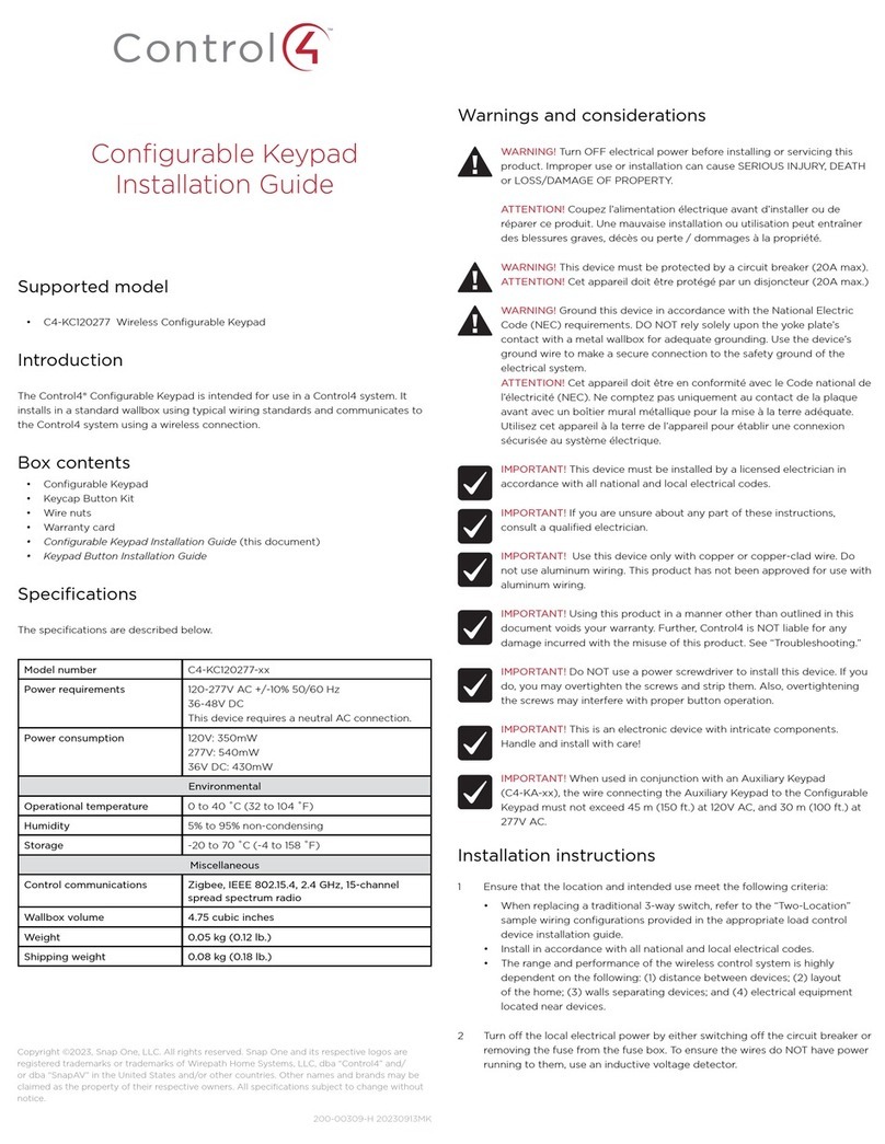
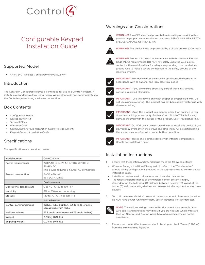
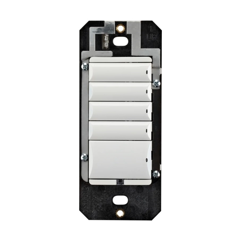
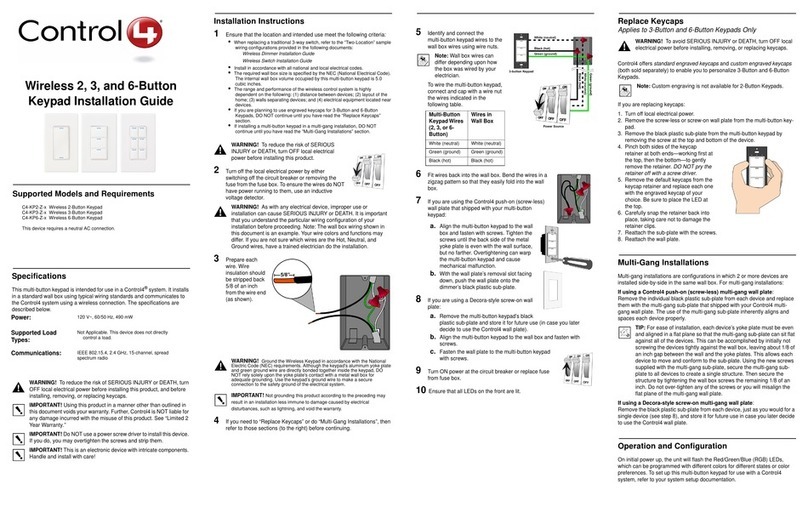
The Control4® Square Wired Configurable Keypad is intended for use in a Control4
system. It installs in a standard square (UK style) or round (EU style) wall box.
Communication to the Control4 system is via RS-485 protocol and wiring. For RS-
485 wiring topologies, refer to the document Keypad Bus Wiring Guide.
Box contents
• Square Wired Configurable Keypad
• Pluggable Terminal Block
• Square Wired Configurable Keypad V2 Installation Guide (this document)
• Warranty card
• M3.5 machine screws (2)
• M4.0 machine screws (2)
• M3.0 thread-cutting screws (2)
Specifications
Model number C4-SKCB2
Power requirements 48VDC
Power consumption Maximum 48VDC 1.2W
Minimum 48VDC 0.7W
Environmental
Operational temperature 0˚C ~ 40˚C (32˚F ~ 104˚F)
Humidity 5% to 95% non-condensing
Storage -20˚C - 70˚C (-4˚F ~ 158˚F)
Miscellaneous
Control communications RS-485
Weight 0.045 kg (0.1 lb)
Shipping weight 0.14 kg (0.3 lb)
Warnings and considerations
Important: Using this product in a manner other than outlined in
this document voids your warranty. Further, Control4 is NOT liable
for any damage incurred with the misuse of this product. See
“Troubleshooting.”
Important: Do NOT use a power screwdriver to install this device. If you
do, you may overtighten the screws and strip them. Also, overtightening
the screws may interfere with proper button operation.
Important: This is an electronic device with intricate components.
Handle and install with care!
Important: This device must be attached to the wall box with screws.
Wall boxes without screw holes for mounting (for example, those that
require expansion clamps) are not compatible with this device.
Important: When installing the keypad in an EU-style (round) wall box,
a Trim Ring (sold separately) must be installed between the keypad and
the wall box. Trim Rings are available in both single-gang and dual-gang
versions.
Caution! Do not exceed the number of keypads per power supply as
indicated in the Keypad Bus Wiring Guide. Exceeding the maximum
number of keypads will result in overheating the wires, failed devices,
and/or communication errors.
Attention ! Ne pas dépasser le nombre de claviers par bloc
d’alimentation comme indiqué dans le Guide de câblage du clavier.
Un dépassement du nombre maximal de claviers entraînera la
surchaue des câbles, périphériques défectueux, et/ou des erreurs de
communication.
Installation instructions
Caution! When wiring the keypad, make sure that either:
• The Bus Power Supply is not powered on.
- OR -
• The pluggable connector is disconnected from the Bus Power
Supply.
Attention ! Lors du branchement du clavier, assurez-vous que
• Le Bus d’alimentation n’est pas sous tension ou
• La prise est déconnecté de l’alimentation.
1 Determine whether the keypad will be installed in a UK-style (square) or EU-
style (round) wall box. If the keypad is to be installed in an EU-style (round)
wall box, ensure that the appropriate trim ring (sold separately) is available
before proceeding.
2 Prepare the cable for termination by stripping the outer sheath and
individual wires, and then wire into the pluggable terminal block.
3 Remove the pluggable terminal block from the back of the keypad, then
connect wires to the terminal block as shown in Figure 1 below.
Figure 1: Keypad wiring
4 If installing in a round wall box, pull the wires and the pluggable terminal
block through the center hole in the trim ring. Refer to Figure 3 for the
proper front/back orientation of the trim ring.
5 Connect the pluggable terminal block to the keypad.
6 Fit the wires back into the wall box.
KeyPad KeyPad
V+ GNDD+ D- V+ GNDD+ D-
To Bus Ethernet
Gateway
To Next Keypad
7 Follow the appropriate instructions for attaching the keypad:
To install in a UK-style square wall box:
a Align the keypad to the wall box as shown in Figure 1 (note the UP
orientation arrow on the keypad), then fasten the keypad to the wall box
using the included M3.5 machine screws.
Figure 2: Square wall box installation
To install in an EU-style round wall box with mounting screws on the left
and right:
a Align the keypad and the trim ring to the wall box as shown in Figure3
(note the UP orientation arrow on the trim ring and keypad).
b Fasten the keypad and trim ring to the wall box using either the included
M3.0 thread cutting screws or the screws that came pre-installed in the
wall box. Note that some pre-installed screws may not have large enough
screw heads to securely hold the keypad.
Figure 3: Round wall box installation—horizontal screw holes
To install in an EU-style round wall box with mounting screws on the top
and bottom:
a Align the trim ring to the wall box as shown in Figure 4 (observe the UP
orientation arrow on the trim ring).
b Fasten the trim ring to the wall box using either the included M3.0 thread
cutting screws or the screws that came pre-installed in the wall box. Note
that some pre-installed screws may not have large enough screw heads to
securely hold the trim ring.
c Attach the keypad to the trim ring with four M2.2 x 6 mm thread-forming
screws included with the trim ring as shown in Figure 4.
Figure 4: Round wall box installation—vertical screw holes
Note: For instructions on installing in a dual EU-style wall box with a
dual trim ring, refer to the Dual Trim Ring Installation Guide.
IMPORTANT! Tighten the screws until the device or trim ring is flush
with the wall surface, but no further. Overtightening can warp the
keypad and cause it to malfunction.
8 Install the buttons (sold separately) following the instructions in the Keypad
Buttons Installation Guide (
ctrl4.co/butn
).
9 Install the Control4 faceplate (sold separately) by placing the top of the
faceplate on the device (note the [“up”] orientation arrow on the inside of
the faceplate) and firmly pressing the bottom until the faceplate snaps into
place against the wall.
Note: To remove the faceplate, use a flathead screwdriver. Insert the
screwdriver into the small gap on the bottom between the faceplate
and the device. Twist the screwdriver blade to pop the faceplate o.
10 Ensure that the Bus Power Supply is installed correctly and powered
on. For instructions, see the Bus Power Supply, 48V Installation Guide
(
ctrl4.co/bps48
).
Wiring diagrams
For bus wiring details, refer to the Keypad Bus Wiring Guide.
Operation and configuration
On initial power up, all status LEDs on the keypad will illuminate blue, indicating
that the device has power. Until the keypad has been configured into a Control4
system, it will not control any loads. To set up this keypad for use with a Control4
system, refer to the Composer Pro User Guide (
ctrl4.co/cpro-ug
).
Button tap sequences
The button tap sequences are defined in the table below. Button tap sequences
that require a single button should use the top-most button installed on the
keypad. Button tap sequences requiring two buttons should use the top-most and
bottom-most (or bottom-left) buttons installed on the keypad.
Function Button sequence
Identify 4
Reboot 15
Factory reset 9-4-9
Unidentify 13-4-13
Troubleshooting
If the LEDs do not light up indicating that the keypad is receiving power::
• Ensure that the Bus Power Supply is powered on.
• Ensure that the Bus Ethernet Gateway is powered on and connected.
• Check for proper wiring (see “Installation Instructions” above).
• For help on the installation or operation of this product, email or call the
Control4 Technical Support Center. Provide your exact model number.
Contact
support@control4.com
or see the website
www.control4.com.
Care and cleaning
• Clean surface of the keypad with a soft damp cloth as needed.
• Do NOT paint the keypad or its wall plate.
• Do NOT use any chemical cleaners to clean the keypad.
Additional resources
The following resources are available for additional support:
• Control4 Knowledgebase and forums
• Control4 Technical Support
• Control4 website:
www.control4.com
• Composer documentation available at
ctrl4.co/docs
.
For the latest version of this document, open this URL or scan the QR code on a
device that can view PDFs.
Regulatory and safety information
To review regulatory information for your particular Control4 products, see the
information located on the Control4 website at:
ctrl4.co/reg
.
Warranty
Visit
www.control4.com/warranty
for details.
More help
For the latest version of this document, open this URL or scan the QR code on a
device that can view PDFs.
MOST RECENT VERSION
ctrl4.co/sq-wiredkp-intl
control4.com | 888.400.4070
Copyright ©2016, Control4 Corporation. All rights reserved. Control4, the Control4
logo, the 4-ball logo, 4Store, 4Sight, Control4 My Home, and Everyday Easy are
registered trademarks or trademarks of Control4 Corporation in the United States and/
or other countries. All other names and brands may be claimed as the property of their
respective owners. All specifications subject to change without notice.
200-00418-C
2016-02-04 MS
C

Other Contro l4 Keypad manuals

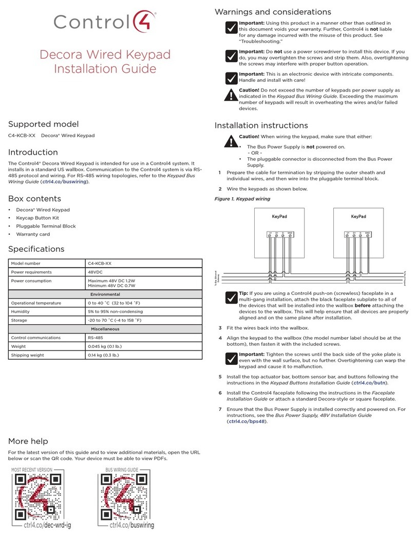
Contro l4 C4-KC120277 User manual

Contro l4

Contro l4 C4-KC120277 User manual

Contro l4 KPZ-3B1 User manual

Contro l4

Contro l4 KPZ-3B1 User manual

Contro l4 C4-KPTK1-M Series User manual

Contro l4

Contro l4 C4-KPTK1-M Series User manual

Contro l4 C4-KA Series User manual

Contro l4

Contro l4 C4-KA Series User manual

Contro l4 Decora C4-KCB-XX User manual

Contro l4

Contro l4 Decora C4-KCB-XX User manual

Contro l4 C4-KC120277 User manual

Contro l4

Contro l4 C4-KC120277 User manual

Contro l4 C4-KC120277 Series User manual

Contro l4

Contro l4 C4-KC120277 Series User manual

Contro l4 C4-KA User manual

Contro l4

Contro l4 C4-KA User manual

Contro l4 C4-KA User manual

Contro l4

Contro l4 C4-KA User manual

Contro l4 C4-KP2-Z User manual

Contro l4

Contro l4 C4-KP2-Z User manual

Contro l4 Decora C4-KCB Series User manual

Contro l4

Contro l4 Decora C4-KCB Series User manual

Contro l4 C4-SKC User manual

Contro l4

Contro l4 C4-SKC User manual

Contro l4 C4-KP2-Z User manual

Contro l4

Contro l4 C4-KP2-Z User manual

Contro l4 C4-SKC User manual

Contro l4

Contro l4 C4-SKC User manual

Contro l4 C4-KP2-Z-x User manual

Contro l4

Contro l4 C4-KP2-Z-x User manual

Contro l4 KPE-10B1 User manual

Contro l4

Contro l4 KPE-10B1 User manual

Contro l4 C4-KA Series User manual

Contro l4

Contro l4 C4-KA Series User manual

Contro l4 C4-KD120 User manual

Contro l4

Contro l4 C4-KD120 User manual

Contro l4 C4-KP2-Z-W User manual

Contro l4

Contro l4 C4-KP2-Z-W User manual

Contro l4 C4-KCB-XX User manual

Contro l4

Contro l4 C4-KCB-XX User manual

Contro l4 Auxiliary C4-KA Series User manual

Contro l4

Contro l4 Auxiliary C4-KA Series User manual

Contro l4 C4-KC240 User manual

Contro l4

Contro l4 C4-KC240 User manual

Contro l4 C4-SKCB-XX User manual

Contro l4

Contro l4 C4-SKCB-XX User manual

Contro l4 C4-KC120277 Series User manual

Contro l4

Contro l4 C4-KC120277 Series User manual

Popular Keypad manuals by other brands

Alarm Lock T3 Prox Cheat list

Alarm Lock

Alarm Lock T3 Prox Cheat list

Unitech K19 Specifications

Unitech

Unitech K19 Specifications

CIDOO V21 Pro user manual

CIDOO

CIDOO V21 Pro user manual

DSC LCD5501Z Using

DSC

DSC LCD5501Z Using

GE AL-1103 user manual

GE

GE AL-1103 user manual

Honeywell 6271C - Ademco TouchCenter Color Keypad Installation and user guide

Honeywell

Honeywell 6271C - Ademco TouchCenter Color Keypad Installation and user guide

Microframe Corporation Visual-Pager 900 Series Installation and specification guide

Microframe Corporation

Microframe Corporation Visual-Pager 900 Series Installation and specification guide

ATA KPX-5 instruction manual

ATA

ATA KPX-5 instruction manual

Metra Electronics RTKP Technical manual

Metra Electronics

Metra Electronics RTKP Technical manual

NAPCO Gemini GEM-TOUCH K Series operating guide

NAPCO

NAPCO Gemini GEM-TOUCH K Series operating guide

Allen-Bradley Poweflex 525 VFD Setting Procedure

Allen-Bradley

Allen-Bradley Poweflex 525 VFD Setting Procedure

AMX AXP-MLCD Dimensional drawing

AMX

AMX AXP-MLCD Dimensional drawing

Salto CONLAN CM1000EMV user manual

Salto

Salto CONLAN CM1000EMV user manual

AMX Metreau DAS-MET-6SRC installation guide

AMX

AMX Metreau DAS-MET-6SRC installation guide

Visonic KP-140 PG2 user guide

Visonic

Visonic KP-140 PG2 user guide

AMX PLK-MSP8 Specifications

AMX

AMX PLK-MSP8 Specifications

Harman AMX MET-13E quick start guide

Harman

Harman AMX MET-13E quick start guide

DMP Electronics 9800 Series quick start guide

DMP Electronics

DMP Electronics 9800 Series quick start guide

manuals.online logo
manuals.online logoBrands
  • About & Mission
  • Contact us
  • Privacy Policy
  • Terms and Conditions

Copyright 2025 Manuals.Online. All Rights Reserved.