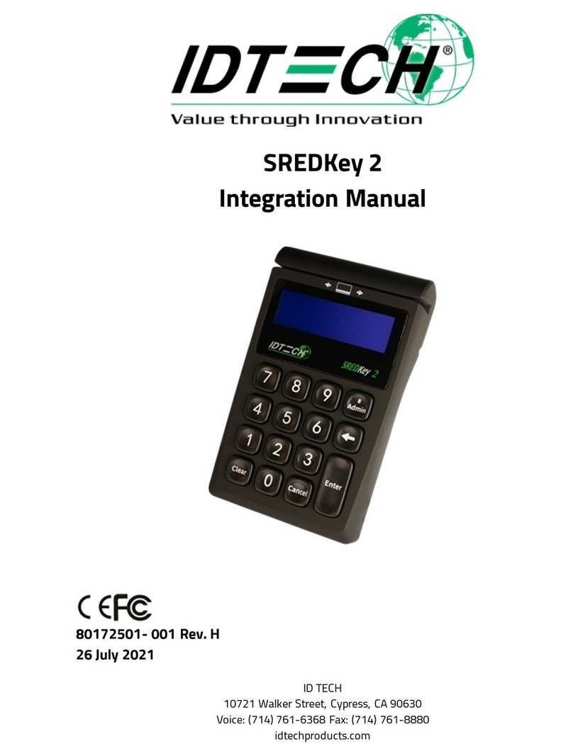
IDTECH SmartPIN L100 User manual

ID TECH
10721 Walker Street, Cypress, CA 90630
Voice: (714) 761-6368 Fax: (714) 761-8880
80141505-001
User Manual SmartPIN L100
Rev. H
25 March 2021

Page | 2
ID TECH
10721 Walker Street
Cypress, CA 90630
Voice: (714) 761-6368 Fax: (714) 761-8880
Copyright © 2021 by ID Technologies, Inc. All rights reserved.
The information contained herein is provided to the user as a convenience. While every effort has been
made to ensure accuracy, ID TECH is not responsible for damages that might occur because of errors or
omissions, including any loss of profit or other commercial damage, nor for any infringements or patents
or other rights of third parties that may result from this information’s use. The specifications described
herein were current at the time of publication but are subject to change at any time without prior
notice.
LIMITED WARRANTY
ID TECH warrants to the original purchaser for a period of 12 months from the date of invoice that this
product is in good working order and free from defects in material and workmanship under normal use
and service. ID TECH’s obligation under this warranty is limited to, at its option, replacing, repairing, or
giving credit for any product that returned to the factory of origin with the warranty period and with
transportation charges and insurance prepaid, and which is, after examination, disclosed to ID TECH’s
satisfaction to be defective. The expense of removal and reinstallation of any item or items of
equipment is not included in this warranty. No person, firm, or corporation is authorized to assume for
ID TECH any other liabilities in connection with the sales of any product. In no event shall ID TECH be
liable for any special, incidental, or consequential damages to purchaser or any third party caused by
any defective item of equipment, whether that defect is warranted against or not. Purchaser’s sole and
exclusive remedy for defective equipment, which does not conform to the requirements of sales, is to
have such equipment replaced or repaired by ID TECH. For limited warranty service during the warranty
period, please contact ID TECH to obtain a Return Material Authorization (RMA) number & instructions
for returning the product.
THIS WARRANTY IS IN LIEU OF ALL OTHER WARRANTIES OF MERCHANTABILITY OR FITNESS FOR
PARTICULAR PURPOSE. THERE ARE NO OTHER WARRANTIES OR GUARANTEES, EXPRESS OR IMPLIED,
OTHER THAN THOSE HEREIN STATED. THIS PRODUCT IS SOLD AS IS. IN NO EVENT SHALL ID TECH BE
LIABLE FOR CLAIMS BASED UPON BREACH OF EXPRESS OR IMPLIED WARRANTY OF NEGLIGENCE OF ANY
OTHER DAMAGES WHETHER DIRECT, IMMEDIATE, FORESEEABLE, CONSEQUENTIAL OR SPECIAL OR FOR
ANY EXPENSE INCURRED BY REASON OF THE USE OR MISUSE, SALE OR FABRICATIONS OF PRODUCTS
WHICH DO NOT CONFORM TO THE TERMS AND CONDITIONS OF THE CONTRACT.
ID TECH and Value through Innovation are trademarks of International Technologies & Systems
Corporation. USB (Universal Serial Bus) specification is copyright by Compaq Computer Corporation,
Intel Corporation, Microsoft Corporation, and NEC Corporation. Windows is a registered trademark of
Microsoft Corporation.

Page | 3
Table of Contents
1 INTRODUCTION............................................................................................................................................... 6
2 FEATURES ....................................................................................................................................................... 7
3 APPLICABLE DOCUMENTS................................................................................................................................ 7
4 ABBREVIATIONS.............................................................................................................................................. 8
5 SPECIFICATIONS .............................................................................................................................................. 9
5.1 Components .....................................................................................................................................................9
5.1.1 Faceplate Color: Silver gray Finish: Brushed finish ..................................................................................9
5.1.2 LCD..........................................................................................................................................................9
5.1.3 LED ..........................................................................................................................................................9
5.1.4 Keys.......................................................................................................................................................10
5.2 Size & weight ..................................................................................................................................................10
5.3 Mounting ........................................................................................................................................................10
5.3.1 L100 Dimensions...................................................................................................................................11
5.4 Tamper Detection...........................................................................................................................................12
1.1 5.4 Tamper Detection.....................................................................................................................................12
5.1 Engaging the Removal Detection Switch for Testing......................................................................................13
5.2 Drop Test ........................................................................................................................................................13
5.3 Dust and Water Resistance.............................................................................................................................13
5.4 Salt spray test .................................................................................................................................................13
5.5 IK Test .............................................................................................................................................................14
5.6 Key Life ...........................................................................................................................................................14
6 ELECTRONIC DESIGN.......................................................................................................................................15
6.1 Power Supply ..................................................................................................................................................15
6.2 USB - Power supplied through USB port Power Management.......................................................................15
6.2.1 Low Power Mode ..................................................................................................................................15
6.3 Reliability & Environmental............................................................................................................................15
6.3.1 Electro-Static Discharges (ESD) ............................................................................................................15
6.3.1 Environmental Temperature Range......................................................................................................15
6.4 Agency Certifications......................................................................................................................................15
7 BASE FUNCTIONALITY.....................................................................................................................................16
7.1 PIN Pad function .............................................................................................................................................16
7.2 Interface function ...........................................................................................................................................16
7.3 Key injection function.....................................................................................................................................16
7.4 Low-Power Modes..........................................................................................................................................16
7.4.1 Sleep Mode ...........................................................................................................................................16
7.4.2 Stop Mode (20 µA)................................................................................................................................16
7.4.3 Bootloader function ..............................................................................................................................16
8 NGA COMMANDS & RESPONSES FORMAT ......................................................................................................17
8.1 LCD & Beeper State & LED..............................................................................................................................17
8.1.1 LCD & Beeper State from Deactivation State to Activation State .........................................................18
8.1.2 Other LCD State for PIN function ..........................................................................................................19
8.1.1 Beeper Tone..........................................................................................................................................20
8.1.2 Keypad Note .........................................................................................................................................20
8.2 Tamper and Failed Self-Check Indicators .......................................................................................................20
8.3 Device Operation Process...............................................................................................................................21
8.3.1 Activation/Removal of Device...............................................................................................................21
8.4 Testing with the L100 .....................................................................................................................................24
8.5 Updating L100 Firmware ................................................................................................................................24
8.5.1 Updating L100 firmware via the VP5300..............................................................................................24
8.5.2 Updating L100 Firmware via Serial-to-USB cable .................................................................................28

Page | 4
8.6 Bootloader Detailed Process ..........................................................................................................................30
8.6.1 Detailed Description..............................................................................................................................30
8.6.1 Enter into Bootloader............................................................................................................................30
8.7 PIN Pad and MSR Pairing Solution ..................................................................................................................30
8.8 General Group (Task)......................................................................................................................................31
8.8.1 Get Firmware Release Version..............................................................................................................31
8.8.2 Get Internal Firmware Version..............................................................................................................32
8.8.3 Enter into Bootloader............................................................................................................................32
8.8.4 Get Serial Number.................................................................................................................................32
8.8.5 Get Model Status ..................................................................................................................................34
8.8.6 Response Example ................................................................................................................................34
8.8.7 Reset .....................................................................................................................................................34
8.8.8 Get Status for Key .................................................................................................................................34
8.8.9 Get Key Status.......................................................................................................................................35
8.8.10 Set Remote Key Injection Timeout ......................................................................................................36
8.8.11 Get Remote Key Injection Timeout......................................................................................................37
8.8.12 Set Date & Time ..................................................................................................................................37
8.8.13 Get Date & Time .................................................................................................................................38
8.8.14 Get All Fix/Removal Records...............................................................................................................38
8.8.15 Enter Stop Mode .................................................................................................................................39
8.8.16 Set Enter Sleep Mode Time .................................................................................................................39
8.9 Other PIN Pad Group (Task)............................................................................................................................40
8.9.1 Get Encrypted PIN .................................................................................................................................40
8.9.2 Get Numeric with Display Message ......................................................................................................41
8.9.3 DisplayMessage and Get Numeric Key .................................................................................................42
8.9.4 DisplayMessage and Get Amount.........................................................................................................42
8.9.5 Get Function Key...................................................................................................................................43
8.9.6 Cancel Command ..................................................................................................................................43
8.9.7 Beeper Control ......................................................................................................................................44
8.9.8 Set PIN Len ............................................................................................................................................45
8.9.9 Get PIN Len ...........................................................................................................................................45
8.9.10 Set Numeric Len ..................................................................................................................................45
8.9.11 Get Numeric Len .................................................................................................................................46
8.9.12 Default PINpad Group All Setting........................................................................................................46
8.9.13 Review PINpad Group All Setting........................................................................................................46
8.9.14 Manual PAN Entry Support.................................................................................................................47
8.9.15 Real Time Key Press Support...............................................................................................................48
8.9.16 Get Numeric with Display Message ....................................................................................................48
8.1 LCD Group (Task) ............................................................................................................................................50
8.1.1 Clear Display .........................................................................................................................................50
8.1.2 Save Prompt Display .............................................................................................................................51
8.1.3 Display Prompt .....................................................................................................................................51
8.1.4 Display Message ...................................................................................................................................51
8.1.5 Default LCD Group All Setting ...............................................................................................................52
8.1.6 Review LCD Group All Setting ...............................................................................................................52
8.1.7 Set Back light of LCD On/Off.................................................................................................................53
8.1.8 Get Back light of LCD On/Off ................................................................................................................53
8.2 RS232 Task Commands...................................................................................................................................53
8.2.1 Set BaudRate ........................................................................................................................................53
8.2.2 Get BaudRate........................................................................................................................................54
8.2.3 Set StopBits ...........................................................................................................................................54
8.2.4 Get StopBits ..........................................................................................................................................55
9 ERROR CODES ................................................................................................................................................56

Page | 5
10 LCD FOREIGN LANGUAGE MAPPING TABLE ...................................................................................................58
11 APPENDIX A: SPECTRUM PRO RELATED COMMANDS....................................................................................60
11.1 CR gets PINPAD UID......................................................................................................................................60
11.2 Get Nonce.....................................................................................................................................................61
11.3 Get DUKPT KSN.............................................................................................................................................61
11.4 Activate and Deactivate Removal Sensor.....................................................................................................62
11.5 Handicap Assistant Signal.............................................................................................................................64
11.6 Display and Get Key (command only between CR-PINPAD).........................................................................64
11.7 Get PIN (command only between CR-PINPAD) ............................................................................................66
11.7.1 Plain text of Truncated Primary Account Number (PAN) pack............................................................68
11.7.2 Plain text of PIN Block.........................................................................................................................68
11.8 Symmetric Key loading .................................................................................................................................68
11.8.1 3B – Set Key: Master and Working Key Description............................................................................68
11.8.2 3C – Set Working Key..........................................................................................................................70
12 APPENDIX B: OPOS/JPOS..............................................................................................................................72
12.1.1 Methods, Properties and Events .........................................................................................................72
13 APPENDIX C: CLEARING THE LOG ..................................................................................................................75

Page | 6
1Introduction
ID TECH’s SmartPIN L100 provides a compact, rugged, secure keypad interface for POS systems requiring
PIN and/or manual-entry capability. The device’s 16-key layout and built-in LCD make it ideal for kiosks
and other unattended applications. When paired with ID TECH’s Spectrum Pro insert reader, the
SmartPIN L100 provides a complete, EMV-ready chip-and-PIN, chip-and-signature, debit/PIN, and MSR
solution that meets ADA, ANSI, and ISO standards for PIN Entry Devices.
For development of applications that communicate with the SmartPIN L100, please ask your ID TECH
representative about the ID TECH Universal SDK for L100 (Windows), which contains libraries (DLLs), C#
source code, a demo app, and documentation for a C# API on Windows. By using the Universal SDK
(which also works with other ID TECH products, such as the Spectrum Pro insert reader), you can save
time developing host applications that talk to the L100 via USB or RS-232 and take advantage of many
convenience methods (including encryption libraries) exposed via the high-level-language API.
Low-level access to L100 via firmware commands can be achieved via USB-HID or RS-232 (serial
connection). This manual documents the low-level commands used to control the L100 and provides
essential information required for establishing a serial connection to the device.

Page | 7
2Features
•PCI 4 certified
•x 4 key layout (0-9, *, #, Cancel, Clear, Enter, Blank), plus 64x128-pixel liquid crystal display
•function keys adjacent to the LCD
•One tri-color LED on the back of the L100 to display unit status
•Meets ADA, ANSI, and ISO standards for a PIN Entry Device
•Audio feedback
•Size and mounting compatible with (mechanical drop-in replacement for) Hypercom Artema
Compact and the Verifone UX100
•Built-in gasket for watertight mounting
•IP65 rated for dust and water resistance
•IK09 rated for intrusion resistance
•Removal Detection and tamper-resistant
•Secure schemes for authorized activation, installation, and injection of keys
•Low power consumption when PIN pad is in sleep mode
•Support for TDES encryption
•Master/Session & DUKPT key management
•Spectrum Pro (standard version) and L100 (standard version) can work either as two standalone
products or be paired together (no special CA certification download required)
•Supports multiple key slots, using the same key storage hardware and firmware design in
Spectrum Pro, which can store fifteen (15) DUKPT keys and twelve (12) 2048-bit RSA public keys
as X.509 certificates
•Encrypted text and clear text entry
•RoHS and REACH compliant
•One-year manufacturer warranty
•Minimum 2,000,000 keystroke operations
•Meets Interac standard for Canadian Market
•When connected to ID TECH Spectrum Pro, supports full functions required by Spectrum Pro,
such as Mutual Authentication with Host through Spectrum Pro, Remote Key Injection through
Spectrum Pro, Firmware Download through Spectrum Pro, Key Pairing (for both PIN Debit and
Chip & PIN), etc.
•Firmware is easily upgraded in the field via the serial communication interfaces
3Applicable Documents
•ISO/IEC 7813 – Identification cards, Physical Characteristics
•ISO/IEC 7811 – Identification cards, Recording Techniques, Magnetic Stripe

Page | 8
4Abbreviations
ANSI
American National Standard Institute
APACS
Association for Payment Clearing Service
API
Application Programming Interface
CPU
Central Processing Unit
DC
Direct Current
DES
Data Encryption Standard
DUKPT
Derived Unique Key Per Transaction, Key management
EMI
Electromagnetic Interference
EMV
Europay, MasterCard, Visa
ESD
Electrostatic Discharge
GND
Signal Ground
Host
A PC or like device with local Application Software for controlling connected SmartPAY
terminals
IEC
International Electrical Congress
ISO
International Organization for Standardization
JPOS
Java for Retail Point-of-Sale
KSN
Key Serial Number
LCD
Liquid Crystal Display
mA
MilliAmperes
MAC
Message Authentication Code
MK/SK
Master Key/Secession Key, Key management
MTBF
Mean Time Between Failures
mV
MilliVolts
OPOS
OLE for Retail Point-of-Sale
PC
Personal Computer or similar hardware device
PCB
Printed circuit board
PCI
Payment Card Industry
PED
PIN Entry Device
PIN
Personal Identification Number
TDES
Triple Data Encryption Standard

Page | 9
19 holes for keys
LCD window
ID TECH logo
5Specifications
5.1 Components
5.1.1 Faceplate Color: Silver gray Finish: Brushed finish
5.1.2 LCD
The L100 has a liquid crystal display with four lines of 20 characters each. With 128 dots to a character,
this means there are 4*20*128 (or 10,240) dots in the LCD.
5.1.3 LED
There is one tri-color (red, yellow, green) LED on the back of the L100 to display unit status. Looking at
the back of the L100, with the top (LCD end) up, the LED is just to the left of the DB-9 connector
opening.
Any given color of LED light can have multiple meanings depending on the context; for details, see the
table under LCD & Beeper State from Deactivation State to Activation State below.

Page | 10
Tactile dot
Color bar
Function keys
5.1.4 Keys
Color: Silver gray Finish: Brushed finish
Layout: Alphabetical characters printed on the keys
Operation keys have engraved, colored bar and symbols: Cancel (red), Clear (yellow), Enter (green).
3 Function Keys are etched or engraved with “F1” “F2” and “F3” respectively Tactile identifier on the
numeral key 5.
Meets ADA standard (which requires embossed symbols to be between 0.6 and 0.9 mm in height).
5.2 Size & weight
Size: 107.5 mm *140 mm *29 mm
Weight: 526 g
5.3 Mounting
Use the provided cutouts to mount the device using standard #10 screws or equivalent (shaft diameter 5
mm or 0.19 inch).
Note: The head of the screw should be greater than 11 mm, less than 13 mm. For best results, use a
washer (with outside diameter greater than 0.43 in. or 11 mm, less than 0.5 in. or 13 mm) under the
screw head.

Page | 11
5.3.1 L100 Dimensions

Page | 12
5.4 Tamper Detection
Tamper detect
Use screw with shaft diam. 'd'
such that 6 mm >= d >= 5 mm
and head diam. 'D' such that
13 mm >= D >= 11 mm

Page | 13
5.1 Engaging the Removal Detection Switch for Testing
The front panel of the SmartPIN L100 incorporates a removal-detection switch behind the bezel's rubber
gasket, on the unit's right-edge flange (when viewed head-on, as in the illustration below).
Engaging the removal-detection feature is only necessary when attempting to pair an L100 with a
compatible ID TECH reader, such as the VP5300. For bench testing, you may find it desirable to clamp
the detection-removal nubs closed using a metal strip held on with two screws (as in the illustration
below). Make sure to do this before powering up the unit. Conversely, power down the unit before
releasing tension on the nubs.
Note: to close the tamper removal switch, 1.63mm of displacement (compression) is required, or
0.056kg of force, but it is recommended that when using a M4-M5 hex nut to mount the unit, a torque
between 1.0-1.2 N.m be applied to allow the gasket to prevent water ingress as well.
5.2 Drop Test
The L100 can withstand 4-ft drop to concrete on 6 surfaces and 4 corners (3 cycles) with no damage and
still maintain functionality.
5.3 Dust and Water Resistance
All front face components are designed for direct liquid spray, and/or splashed or spilled liquids. The
L100 passes IP65 ratings.
5.4 Salt spray test
Faceplate, metal keys, and mounting plate pass the salt spray test.

Page | 14
5.5 IK Test
The front face is impact resistant to meet IK9 rating (10 joules of impact energy, equivalent to dropping
a 5kg object from 20 cm height).
5.6 Key Life
The L100 is designed for a minimum of 2,000,000 keystroke operations per key.

Page | 15
6Electronic Design
6.1 Power Supply
The SmartPIN L100 supports three different modes:
•RS232 – Requires power supplied by an external A/C power adapter (5VDC).
•UART - RJ45 cable connects directly to the Spectrum Pro insert reader; also requires an external
A/C power adapter (5VDC).
•USB – Connects directly to the host, which provides power through the USB interface.
6.2 USB - Power supplied through USB port Power Management
Power management includes several parts:
1. System voltage supply
a. An LDO chip is used to convert 5V external voltage to 3.3V, which is the common voltage
for all chips and components used in this device.
2. Battery
a. A battery supplies the power for the SRAM to keep the keys in storage.
6.2.1 Low Power Mode
In low power mode, the voltage of all peripherals is cut off and wakes up by key press and
communication from PC.
6.3 Reliability & Environmental
MTBF: 425010 hrs (FR=2352 FITs, BasicR=0.979)
FR is failure rate. FITs is failures per billion hours. MTBF is the Mean Time between Failures in hours.
BasicR (Reliability) is the probability that the circuit, taken as a purely Serial configuration, will operate
without failure for the mission time. For example, if the BasicR = 0.837438, then
the circuit has a probability of 0.837438 (or 83.74%) of working without a failure for the mission time
duration.
6.3.1 Electro-Static Discharges (ESD)
The L100’s electronics can survive electrostatic discharges of 6kV contact and 12kV air discharge with no
loss of communications, per ID TECH ESD testing procedures.
6.3.1 Environmental Temperature Range
Operating
-25 to 70°C (-13 to 158°F) [non-condensing]
Storage
-30 to 80°C (-22 to 176°F) [non-condensing]
Relative humidity:Maximum 95% (non-condensing)
6.4 Agency Certifications
FCC CLASS B & CE PCI 4.1

Page | 16
7Base Functionality
7.1 PIN Pad function
•PIN MK/SK, DUKPT Key Management
•TDES Encryption (keystrokes are not sent in the clear)
•4 x 4 key layout with 0-9 numerical keys, *, #, Cancel, Clear, Enter, Blank, and 3 additional
Function keys adjacent to the bottom of the LCD screen: F1, F2, F3 (function defined by
application)
•Supports clear text entry
•PCI-PTS 4.x certified
7.2 Interface function
•USB-HID and RS232 interfaces connect via one DB9 connector on the back of the PIN pad that
plugs into the appropriate interface cable.
•The L100 supports both USB-HID and RS232 interfaces for the regular host.
RS232 :
•Baud rates supported: 2400, 4800, 9600, 19200, 38400, 115200 bps
•Data bits: 8
•Parity: Odd, Even, or None
•The COM default settings are initialized to: 38400, 8, 1, & None
USB-HID:
•PID: 0x1050
•VID: 0x0ACD
7.3 Key injection function
•Compatible with FutureX SKI 9000 HSM for PIN Key Injection.
•Can communicate with HSM using the key injection protocol for unattended products.
7.4 Low-Power Modes
7.4.1 Sleep Mode
While using the RS232 interface, Sleep Mode is controlled by a timeout after the L100 is idle for a
specified time (default is 120s). While using the USB interface, Sleep Mode is controlled by the USB
suspend and resume signals. Sleep Mode is used for battery-operated and solar-powered systems. It
reduces power consumption to a much lower level (1 mA USB, 8 mA RS232) than full-power mode (200
mA) but leaves the device able to be woken up by key press or communication from the host.
7.4.2 Stop Mode (20 µA)
Stop Mode is controlled by the application through a specific command. Stop Mode reduces power
consumption to the lowest possible level (20 µA). An L100 in Stop Mode can only be woken up by a
physical key press.
7.4.3 Bootloader function
The firmware can be upgraded via USB/RS-232 port (Baud rate is 115200).
For detailed information, please refer to document P/N 80000420-001, Bootloader Firmware
Specification (V52).doc.

Page | 17
8NGA Commands & Responses format
The L100 uses NGA protocol commands and responses in general communication. The format is:
<STX> <Len_Low><Len_High> <Command Body / Response Body / Notification Body>
<CheckLRC> <CheckSUM> <ETX>
Where:
•<STX> is 0x02 and <ETX> is 0x03
•<Len_Low><Len_High> is length of <Command Body / Response Body / Notification Body>
•<CheckLRC> is LRC (8-bit XOR) of all data bytes in <Command Body / Response Body /
Notification Body>
•<CheckSUM> is SUM (8-bit SUM) of <Command Body / Response Body / Notification Body>
oResponse Body: <Response Status> + [<Response Data>]
o<Response Status>: status of the response. 1 byte. NAK: 0x15
oACK: 0x06
o<Response Data>: main response string.
oIf <Response Status> is ACK: More bytes needed.
oIf <Response Status> is NAK: Response data is Error codes (2 bytes).
oNext section lists <Command Body>, <Response Body>, and <Notification Body>
detailed.
8.1 LCD & Beeper State & LED
Note:
Item
Definition
Device is in a Deactivation
State
Tamper Switch Or Battery Error
Important Data - No
At least one of Public Key, Firmware Key, Check Value,
and/or Numeric Key was not loaded
Important Data - Have
Loaded Public Key, Loaded Firmware Key, Loaded
Check Value, and Loaded Numeric Key

Page | 18
8.1.1 LCD & Beeper State from Deactivation State to Activation State
•PK – Public Key (Manufacture Key)
•FK – Firmware Key
•NK – Numeric Key CV – Check Value
•DTV – Date & Timer Value
Device State
Definition
LCD Display Message
Beeper State
LED auxiliary indicator
Deactivation
Device – Removal
Security Chip – De-
activation
No PK, FK, CV,
NK, and DTV
Line0: Fatal Error
Other line:
Battery/SDI1/SDI2/Other
Other lines are used to
describe the cause to de-
activation
Always beeping,
quick
Steady Red
Load Important
Data State
Device – Removal
Activation
Need to load
PK, FK, CV,
NK, and DTV
Load Check Value &
Related Key
Always beep
(slow)
Steady Red
Activation1
Activation
PK, FK, CV, NK,
and DTV loaded
successfully
No DUKPT Key or
Master Key
Ready
Not beeping
If user passwords not
set: Blink Yellow
If user passwords set
or if legally in
Removal
State: Steady Yellow
If legally in Install
State: Steady Green
Load Key State
Activation
PK, FK, CV, NK,
and DTV loaded
successfully
Unit prepared to load
DUKPT Key or Master
Key
Refer to
XX DUKPT Key
Loading … Master Key
Loading…
Refer to Key
Loading Note
If user passwords not
set: Blink Yellow
If user passwords set
or if legally in
Removal
State: Steady Yellow
If legally in Install
State: Steady Green
Suspend for Get
PIN
Activation
PK, FK, CV, NK
and DTV loaded
successfully
GET PIN more than 120
times per hour by MKSK
Line0: SUSPEND
Other lines: Get PIN
Other lines are used to
describe the cause to
suspend
Not beeping
If not set user
passwords: Blink
Yellow If set user
passwords:
If legally Removal
State: Steady Yellow If
legally Install State:
Steady Green

Page | 19
Device State
Definition
LCD Display Message
Beeper State
LED auxiliary indicator
Activation2
Activation
PK, FK, SCV,
NK, and DTV loaded
successfully
At least DUKPT Key or
MKSK is loaded
successfully
Ready
Not beeping
If not set user
passwords: Blink
Yellow If set user
passwords:
If legally Removal
State: Steady Yellow If
legally Install State:
Steady Green
8.1.2 Other LCD State for PIN function
State
LCD Display Message
Note
Checking Firmware
Firmware Checking…
Get Encrypt PIN
Line0:xxxxxxxx
Line1:xxxxxxxx
Line2:xxxxxxxx
Line3:***……
Get Numeric
Line0:xxxxxxxx
Line1:xxxxxxxx
Line2:xxxxxxxx
Line3: xxxxxxxx…
The Message and Plaintext Numeric
Display is defined by Command.
Get Numeric
Line0:xxxxxxxx
Line1:xxxxxxxx
Line2:xxxxxxxx
Line3:***……
The Message and Star Display is
defined by Command.
Suspend
Line0: SUSPEND
Line1: PWD ERR
Removal Detection Password Error 3
times continuously
Modify default password
Please input one password
********
Please input new password
********
Please input new password again
********
Please input another password
********
Please input new password
********
Please input new password again
********
Modify two groups’ default passwords
to user passwords.
Input Removal Detection
Enable/Disable user
passwords
Please input one new password
********
Please input another new password
********
Enter two groups’ user passwords.
Checking Firmware
Firmware Checking…
Get Encrypt PIN
Line0:xxxxxxxx
Line1:xxxxxxxx

Page | 20
Line2:xxxxxxxx
Line3:***……
Suspend
Line0: SUSPEND
Line1: Get PIN
Get Encrypted PIN under MKSK more
than 120 times per hour.
8.1.1 Beeper Tone
Name
Tone Note
Normal Tone
beep tone once
Complete Tone
beep short tone 2 times
invalid Tone
beep short tone 3 times
8.1.2 Keypad Note
F1
F2
F3
1
2
3
Cancel
4
5
6
Backspace
7
8
9
Enter
*
0
#
Blank
8.2 Tamper and Failed Self-Check Indicators
The SmartPIN L100 displays the following indicators when it has been tampered or has any of the other
following internal issues, such as an expired certificate, missing key, or similar fault discovered during a
self-check.
Indicator
Tampered Status
Other Issue Status
Diagnostic LED
Solid red
Solid red
LCD Display Message
Fatal Error
Others
Fatal Error
Battery
Buzzer
Quick beep
Quick beep
Table of contents
Other IDTECH Keypad manuals
Popular Keypad manuals by other brands

Upgrading everyday security
Upgrading everyday security EL-2620 introduction
YASKAWA
YASKAWA JVOP-KPLCA04A Series installation manual
UTC Fire and Security
UTC Fire and Security interlogix ATS1135 Installation sheet
Sigma
Sigma Apollo user manual
NAPCO
NAPCO Gemini GEM-RP2ASe2 operating guide

Honeywell
Honeywell 6271C - Ademco TouchCenter Color Keypad Installation and user guide
