Sensor Line SL MD-220 User manual

Optical Transmittance Analyzer
SL MD-220
USER'S MANUAL
Hardware Version 2.0 / Software Version 1.3
Sensor Line - Gesellschaft für
optoelektronische Sensoren mbH
Carl-Poellath-Str. 19
D-86259 Schrobenhausen
- Germany -
Tel.: +49 (0) 8252 / 8943-0
Fax.:+49 (0) 8252 / 8943-11
Email: [email protected]
www.sensorline.de

SL MD-220 User's Manual
- 2 -
Table of Contents
1. General..............................................................................................................................4
1.1 Introduction..................................................................................................................4
1.2 Principle of Operation..................................................................................................4
1.3 Technical Data ............................................................................................................6
2. Hardware Section.............................................................................................................7
2.1 Dimensional Drawing...................................................................................................7
2.2 Handling Precautions ..................................................................................................7
2.3 Installation ...................................................................................................................8
2.4 System Terminal..........................................................................................................8
2.4.1 Mechanical............................................................................................................8
2.4.2 Connections..........................................................................................................8
2.4.2.1 Power Supply Terminal......................................................................................8
2.4.2.2 Optocoupler Outputs..........................................................................................9
2.4.2.2.1 Internal Circuitry............................................................................................9
2.4.2.2.2 External Wiring.............................................................................................9
2.4.2.2.2.1Generating Voltage Output Signals ........................................................9
2.4.2.2.2.2Driving Loads........................................................................................10
2.5 RS-232 Interface .......................................................................................................11
2.5.1 Connector ...........................................................................................................11
2.5.2 Wiring..................................................................................................................11
2.6 Reset Switch..............................................................................................................12
2.7 8-Way SIL Switch......................................................................................................12
2.8 Jumpers.....................................................................................................................12
2.9 Status LEDs ..............................................................................................................13
2.10 Measuring Pins..........................................................................................................13
2.11 Fiber Optic Receptacles............................................................................................14
2.12 JTAG connector ........................................................................................................14
3. Software Section............................................................................................................15
3.1 General Description...................................................................................................15
3.2 Details .......................................................................................................................16
3.2.1 Startup Procedure...............................................................................................16
3.2.2 Timing.................................................................................................................17
3.2.2.1 Program cycle time..........................................................................................17
3.2.2.2 Watchdog Timer..............................................................................................17

SL MD-220 User's Manual
- 3 -
3.2.3 Triggering............................................................................................................17
3.2.3.1 Trigger Timing .................................................................................................17
3.2.3.2 Nominal Trigger Threshold..............................................................................17
3.2.3.3 Adaptive Trigger Threshold.............................................................................18
3.2.4 SIL Switch and Jumper Settings.........................................................................19
3.2.4.1 Switch Settings................................................................................................19
3.2.4.2 Jumper Settings...............................................................................................20
3.2.5 Status Outputs....................................................................................................20
3.2.5.1 Status LEDs.....................................................................................................20
3.2.5.2 System Terminal Block....................................................................................20
3.2.5.3 Status Table ....................................................................................................21
3.2.6 RS-232 Interface.................................................................................................22
3.2.6.1 General............................................................................................................22
3.2.6.2 Comm Parameters...........................................................................................22
3.2.6.3 Output Modes..................................................................................................22
3.2.6.3.1 Voltage Mode .............................................................................................22
3.2.6.3.2 Percent Mode .............................................................................................23
3.2.6.3.3 Transmittance Mode...................................................................................23
3.2.6.3.4 Status Mode ...............................................................................................24
3.2.6.3.5 Off Mode.....................................................................................................25
3.2.6.3.6 Software Version Query..............................................................................25
3.2.6.3.7 Fast Mode...................................................................................................25
3.2.6.3.8 Special Output Modes................................................................................25
3.2.6.4 Commands ......................................................................................................26
3.2.6.4.1 System Reset Command............................................................................26
3.2.6.4.2 Threshold Reset Commands......................................................................26

SL MD-220 User's Manual
- 4 -
1. General
1.1 Introduction
The SENSOR LINE MD-220 is a two-channel static opto-electronic interface for SENSOR
LINE’s SPZ/SPT fiber optic load sensors. This two-channel interface supplies light to two
fiber optic sensors, monitors the amount of light transmitted through the sensors and detects
small changes caused by loads applied to the sensors. With its advanced circuitry, the
interface can detect a load on a sensor for as long as it is applied to the sensor.
The MD-220 incorporates a TI MSP-430 embedded microcontroller, programmable via a
JTAG interface. It has a 10-wire screw-clip interface with power supply terminals and four
floating optocoupler outputs. It also has a RS-232 interface for input and output of data.
Direct external control is possible through the use of an 8-way SIL switch, two jumpers and a
reset switch. For quicker troubleshooting, six LED status displays show the function of the
interface and there are five easily accessible test points for analog measurements.
Power consumption has been minimized by circuitry that operates the transmitter diodes in
series while independently controlling the current through each diode. The MD-220 comes
with two different kinds of transmitter diodes, a near infrared diode giving each channel a
dynamic range of 30 dB and a more economic red diode for a dynamic range of 20 dB.
The hardware and software for the MD-220 come in different versions. This manual is
divided into a hardware and a software section.
Please ensure that you have the correct version of this manual.
1.2 Principle of Operation
7.5M
470k
D
A
A
D
D
A
GNDGND
MONx
ANAx
I2 I1
The drawing above is a simple circuit diagram of one channel. When the photodiode is
illuminated with light from the sensor it proportionally sinks a current to the incoming light
power. This causes the output of the OP to go high so the current is supplied across the
7.5M resistor. When the light becomes too bright the OP output is clipped, and the controller
supplies additional current via the DAC and the 470k resistor until the OP output is
“unclipped.”
6PDOO FKDQJHV RI SKRWR FXUUHQW DUH DPSOLILHG E\ WKH 23 E\ D IDFWRU RI 0
9
$
The controller measures this voltage ("Analog Voltage" or VANAx) as well as the voltage

SL MD-220 User's Manual
- 5 -
produced by the DAC ("Monitor Voltage" or VMONx) with a resolution of 12 Bits. An additional
DAC controls the light power fed into the sensor.
Both voltages can be measured at test pins. Since the sensitivity of the photodiode is about
0.5 A/W the incoming light power
-
can at any time be calculated using the formula
-
= 2 W
A·
VMONx
N
+ VANAx
0

SL MD-220 User's Manual
- 6 -
1.3 Technical Data
Device Type: MD-220
Hardware
Hardware Version: 2.0c STD-1
Number of Channels: 2
Size: 100x110x19 mm (3.54x4.33x.75 in)
Electrical Connections: 10-wire screw terminal block
RS-232, 3-wire**
5 test points
Optical connections: SMA 905
LED Peak Output Wavelength 850 nm (NIR) / 660 nm (VIS red)
Maximum Sensor Loss: 30 dB (NIR) / 20 dB (VIS)
Relative Humidity: 80% at 25°C (77°F)
Temperature Range: -40°C to 85°C (-40°F to 185°F)
Supply Voltage: +12 to +24 VDC
Supply Current: < 140 mA
Analog Output at Test Points: 0-10 V
Optocoupler Outputs max.: OFF: 50V/<1uA
ON: 5V/50 mA (250 mW @ 25°C)
RS-232 connector 9-pin DSUB male
Velocity Range: 1 to 250 km/h (0.6 to 155 mph)
Feeder Length: up to 250 meters (820ft)
Comparative Laser Class: 3A (NIR, sensor disconnected)
EMV/EMI: Meets CE-requirements
Software
Program Name: MD220STD
Program Version: 1.3
Program cycle time:
V
Watchdog expiration time 4 ms
Triggering Thresholds 0.2%, 0.4%, 0.8%, 1.6%
change of light transmittance**
Adaptive Threshold 0%, 6.25%, 12.5%, 25%, 50%
of load signal**
Hysteresis: ± 2 digits
Minimum input ON time: 3 program cycles (1.5 ms)
Minimum output ON time: 3 program cycles (1.5 ms) /
40 program cycles (20 ms)*
80 program cycles (40 ms)*
Maximum output ON time: 30 s
RS-232 Baud Rate 9600 / 19200 / 115200 Bd**
Data Bits 8
Stop Bits 1
Parity N (no parity)
* selectable with jumper J1, ** selectable with SIL switch
SL MD-220 User's Manual
- 7 -
2. Hardware Section
The PCB version is found on the bottom layer of the PCB. This manual is for hardware
version 2.0.
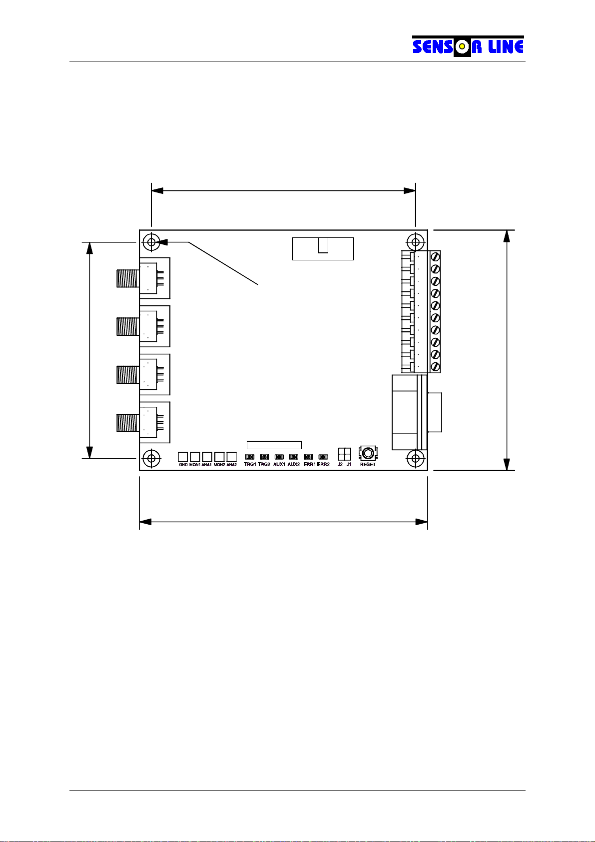
2.1 Dimensional Drawing
.
Receiver 2
Transmitter 1
Receiver 1
Transmitter 2
100 (3.937)
120 (4.724)
110 (4.331)
90 (3.543)
JTAG
Connector
RS-232
Connector
Reset
Switch
Jumpers
System Terminal
Status LEDs
Test Points
Channel 1
Receiver
Channel 1
Transmitter
Channel 2
Transmitter
Channel 2
Receiver
+12..24VDC
GND
AUX2-
AUX2+
AUX1-
AUX1+
TRG2-
TRG2+
TRG1-
TRG1+
Through Holes Ø3.1 (.122)
Maximum Height 19 (.748) - Dimensions in mm (in)
Fiber Optic SMA 905 Receptacles
1
2
3
4
5
6
7
8
90
SIL-Switch
2.2 Handling Precautions
The MD-220 is delivered without a housing so handle it the same way as a PC card. Some
of the interface components are sensitive to electrostatic discharge (ESD). Leave the
interface inside its conductive bag until installation. Discharge yourself by touching a
grounded conductor before touching the interface. The receptacles are either non-
conductive or grounded and the system outputs have a special protective circuitry. It is
relatively safe to handle the interface by these parts. If conductive spacers are used, the
interface may be handled by these spaces because the rims of the through-holes are also
grounded. Before pressing the reset switch by hand first discharge yourself. The jumpers
and LEDs are connected directly to the controller and should never be touched. The test
points are connected to OP outputs, which are also sensitive to ESD. Discharge any
measuring clips on the GND pin before contacting one of the other test points.

SL MD-220 User's Manual
- 8 -
2.3 Installation
The MD-220 PCB has four Ø3.1mm (0.12”) through-holes, allowing it to be mounted on any
appropriate flat surface by means of M3 screws. At least 5mm (0.2”) spacers are
recommended to ensure a sufficient gap between the PCB and the mounting surface.
2.4 System Terminal
2.4.1 Mechanical
The system terminal is a 10-wire screw terminal block which accepts 0.14–1.5 mm2(26–16
AWG) wires. To fasten the screw clips a screwdriver with a blade up to 3.5 mm wide can be
used. The terminal block can either be a flat or angled design, the latter is used if several
interfaces are stacked.
2.4.2 Connections
Pinning Sign Description
+12...24VDC Supply Voltage
GND Ground
AUX2–
AUX2+ }Auxiliary Optocoupler Output 2
(Low Resistance = Sensor Failure)
AUX1–
AUX1+ }Auxiliary Optocoupler Output 1
(Low Resistance = TRG1 AND TRG2)
TRG2–
TRG2+ }Trigger Channel 2 Optocoupler Output
(Low Resistance = Load Response)
TRG1–
TRG1+ }Trigger Channel 1 Optocoupler Output
(Low Resistance = Load Response)
2.4.2.1 Power Supply Terminal
Terminals 0 and 1 of the system terminal block are for connection of a 12-24 VDC power
supply. The MD-220 has built-in voltage regulators and is reverse voltage protected. The
interface draws a maximum of 140 mA. Connect the negative output to Terminal 1 and the
positive output to Terminal 0.

SL MD-220 User's Manual
- 9 -
2.4.2.2 Optocoupler Outputs
2.4.2.2.1 Internal Circuitry
68 V
0.25W
100 Ohms
Optocoupler
H11G1 + Terminal
–Terminal
The above schematic shows the internal circuitry of the TRG1 & 2 and AUX1 & 2
optocoupler outputs. When the phototransistor is illuminated by the LED (ON condition)
current flows into the + terminal and out of the - terminal. The resistor limits the maximum
allowable current to 50mA. Therefore, any DC voltage applied directly to the outputs must
not exceed 5V when the phototransistor is conductive because the maximum power the 100
Ohm resistor can dissipate is 250mW.
When the phototransistor is not conductive the maximum voltage is limited by the zener
diode to 68V. If a voltage above that value is applied (even with additional resistors), the
output might appear conductive but the phototransistor is not. To avoid any glitches caused
by voltage spikes or surges the optocoupler outputs should not be operated with voltages
above 50V.
2.4.2.2.2 External Wiring
The optocoupler outputs are not connected to any voltage source so there are many ways to
obtain various kinds of output signals. In all cases an external power supply must be added.
The outputs behave as switches with the restriction that current can only flow in one
direction. Below are examples of how the outputs may be wired.
2.4.2.2.2.1 Generating Voltage Output Signals
Voltage output signals are required if high impedance inputs, like those on an oscilloscopes,
are connected. The wiring from the diagrams below can be used if the voltage from the
available source has the required value or is not critical.
10k
+ Terminal
–Terminal
+
–
+ Vout
–Vout
Positive output voltage going
LOW on ON condition
10k
+ Terminal
–Terminal +
–
+ Vout
–Vout
Zero output voltage going
HIGH on ON condition
SL MD-220 User's Manual
- 10 -
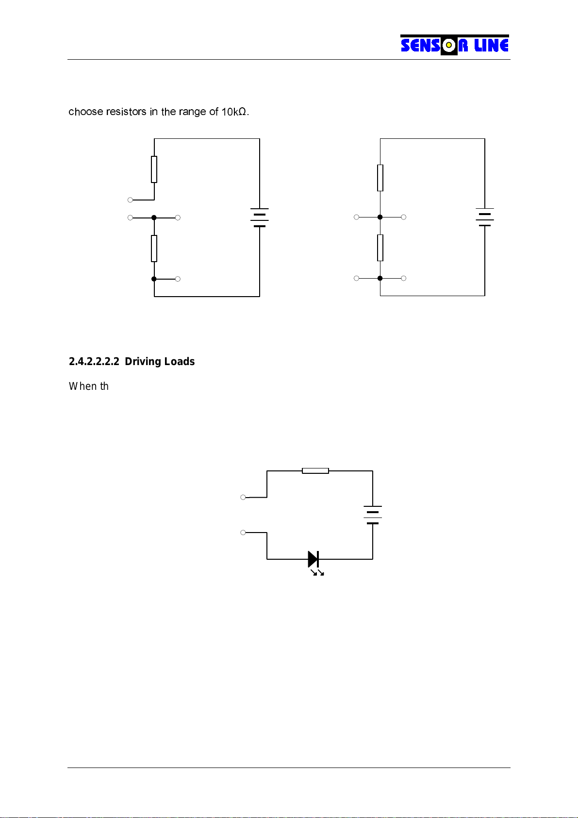
If the voltage available is too high for the intended inputs a second resistor must be added in
order to create a voltage divider as given in the schematics below. It is generally safe to
FKRRVH UHVLVWRUV LQ WKH UDQJH RI N
2.4.2.2.2.2 Driving Loads
When there are no high impedance inputs that inhibit the flow of current it is not necessary to
generate a voltage. In this case the optocoupler output can be used as a switch to turn
current on and off. The wiring below shows how to operate an LED or drive optocoupler
inputs or relays. The current must be limited to a maximum of 50mA with an appropriate
resistor.
R
+ Terminal
–Terminal
+
–
LED
Driving a LED
+ Terminal
–Terminal
+
–
+ Vout
–Vout
Zero output voltage going
HIGH on ON condition
+ Terminal
–Terminal
+
–
+ Vout
–Vout
Positive output voltage going
LOW on ON condition
SL MD-220 User's Manual
- 11 -
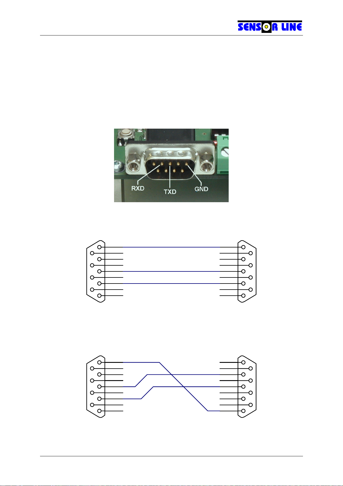
2.5 RS-232 Interface
The MD-220 has a three-wire RS-232 interface with a male 9-pin DSUB RS-232 connector. It
behaves like a PC, sending data on the TXD line (Pin 3) and receiving on the RXD line (Pin
2). It can be connected directly to a printer with a standard RS-232 cable. To connect it to a
PC a null-modem cable is required, similar to the connection between two PCs. Please refer
to the software section for communication parameters as baud rate, parity, etc.
2.5.1 Connector
2.5.2 Wiring
1
6
2
7
3
8
4
9
5
MD-220
Female Connector
1
6
2
7
3
8
4
9
5
RS-232 device
Male Connector
GND
TXD
RXD
Standard RS-232 Cable
1
6
2
7
3
8
4
9
5
PC
Female Connector
1
6
2
7
3
8
4
9
5
MD-220
Female Connector
GND
Null-Modem Cable

SL MD-220 User's Manual
- 12 -
2.6 Reset Switch
Pressing the reset switch causes a hardware reset of the microcontroller.
The two pads next to the right of the switch are connected in parallel and can accept a two-
pin header to allow for connection of an external switch.
2.7 8-Way SIL Switch
The SIL switch consists of eight individual switches which are connected to I/O pins of the
microcontroller. They are used to signal different conditions in order to modify the behavior
of the interface without re-programming it. Please refer to the software section of this manual
for the different switch settings.
2.8 Jumpers
The headers J1 and J2 can be used for the same purpose as the SIL switch (see above) by
installing jumpers or connecting external switches. They can also be used as I/O
connections for various purposes. Please refer to the software section of this manual for
more information.
SL MD-220 User's Manual
- 13 -
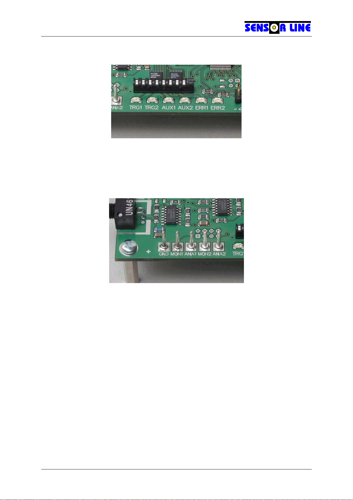
2.9 Status LEDs
There is a display of six LEDs controlled by the microcontroller. TRG1, TRG2, AUX1 and
AUX2 are yellow, and ERR1 and ERR2 are red. Please refer to the software section of this
manual for the meaning of the LED signals.
2.10 Measuring Pins
There are five test points with 1.3mm (0.05”) pins for measuring the analog voltages
evaluated by the microcontroller. The meaning of these voltages is thoroughly explained in
paragraph 1.2 on page 4.
Label Signal Sign
GND Ground –
MON1 Monitor Voltage Channel 1 VMON1
ANA1 Analog Voltage Channel 1 VANA1
MON2 Monitor Voltage Channel 2 VMON2
ANA2 Analog Voltage Channel 2 VANA2
SL MD-220 User's Manual
- 14 -
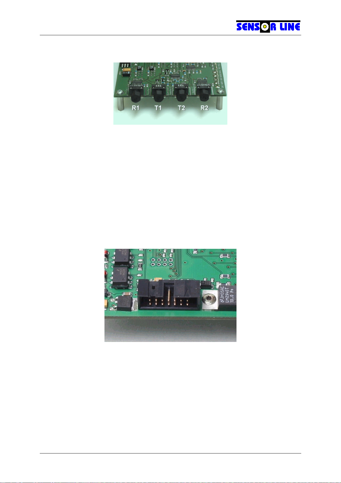
2.11 Fiber Optic Receptacles
Two fiber optic load sensors can be connected to the MD-220 via four SMA 905 fiber optic
receptacles. Viewed from the front the receptacles for Channel 1 are on the left hand side
and those for Channel 2 on the right hand side. The transmitters are the inner receptacles.
Do not stare into the transmitters when the interface is powered and there is no sensor
connected.
Fasten the sensor’s fiber connectors to the transmitter or receiver by screwing tightly on by
hand (the tighter, the smaller the attenuation). DO NOT USE PLIERS. The transmitter and
receiver connectors are interchangeable for each channel. The transmitter connectors are
not interchangeable i.e. a sensor connected for example to Transmitter 1 and Receiver 2 will
not work.
2.12 JTAG connector
The JTAG connector is used for programming the microcontroller at the factory. If you are
intending to re-program the device in the field please contact Sensor Line GmbH for further
information.

SL MD-220 User's Manual
- 15 -
3. Software Section
The following refers to the MD-220 program MD220STD version 1.3.
3.1 General Description
The program executed by the microcontroller controls all functions of the MD-220. Detecting
a load applied to the sensor is difficult because of the large variation in sensor transmittance
versus the small amount of transmittance change when load is applied. For example, if the
sensor transmittance could change by a factor of 100 (20 dB) and the transmittance change
caused by a load was 1% (=1/100) the complete light measuring range would have to be
resolved to 1/10000 of its value in order to detect the load. This is more than twice the
resolution of a 12-bit ADC.
To overcome this difficulty the microcontroller controls the photo currents detected by the
input amplifiers in two ways. First, it can vary the transmitter currents by a factor of ten.
Second, it can subtract an offset of up to 16 times the range of the amplifiers from their input
current. With growing sensor transmittance the light power fed into the sensors is reduced in
order to avoid clipping of the signal. When the minimum value is reached the controller
compensates for further increases in sensor transmittance by subtracting increasing portions
of the photo current before the remainder is fed into the amplifiers (see paragraph 1.2 on
page 4).
After startup the program uses these methods to adjust the amplifiers' output voltages (called
"analog voltages") to a value in the upper region of the ADCs' measuring range. Then it
establishes a threshold below that value corresponding to a constant fraction of the light
detected. After this initialization process the program enters its main loop. Here it monitors
the analog voltages and checks if they have dropped below the threshold values, thus
signaling load being applied to the sensors.
As long as there is no load detected the thresholds are carefully adapted to slow changes
(drifting) of the detected light and the analog voltages are adjusted,if necessary. However, if
there is load this process cannot be continued since it is impossible to determine whether a
change of the detected light is due to drifting or due to a change of the load. As equipment
does not stop drifting when there is load on the sensor the interface cannot be allowed to
detect load for infinite time. If during load detection the amount of light detected without any
load drifted below the stored threshold, the interface would no longer be able to notice the
load being removed; it would "hang".
For this reason there is a maximum detection time of 30 seconds. When this time has
elapsed, the interface performs an initialization process similar to the one at startup. The
interface is then ready to detect additional load being applied to the sensor. The original
load effect is regarded as intrinsic sensor attenuation. When the original load is removed the
threshold is adapted immediately.
When the sensor is broken (or disconnected) no light arrives at the receiver and the interface
is unable to detect any load. If the sensor fails during operation, the detected light falls
below the threshold and is reported as load being detected. Therefore, sensor failure during
operation is first reported as a load detected, and it changes to an error signal after 30
seconds.

SL MD-220 User's Manual
- 16 -
3.2 Details
3.2.1 Startup Procedure
After power-up or when a program reset is initiated the MD-220 first tries to adjust itself to the
particular sensors attached. This process takes about one second and is signaled by both
ERRx LEDs (see paragraph 3.2.5.1 on page 20) flashing at 8 Hz.
If insufficient light is detected, i.e. if there is no sensor connected to a channel or the
connected sensor is broken, the respective ERRx LED comes on continuously along with
the AUX2 LED. The AUX2 optocoupler output becomes conductive and the associated
TRGx LED flashes ten times at 2 Hz. The TRGx LED is then switched off.
In the case that there is too much light detected (which may happen when an interface with
infrared transmitters is used in conjunction with a low loss sensor) the ERRx and AUX2 LEDs
and the AUX2 optocoupler outputs behave the same way but the TRGx LED does not flash.
If the sensor loss is within a range where the interface can successfully adjust itself the
program waits for the transmitter to stabilize its output power. This is necessary because
during power-up the transmitter becomes warm, causing a slight decrease in its brightness
during the first few seconds.
Since it is not possible to derive a measure for the sensor loss from the analog voltages at
the test pins, the interface signals the virtual sensor loss during warmup time. It cannot
determine the real sensor loss. Rather, the sensor loss, in this, cases, defines a certain
value within an internal "theoretic" dynamic range of 30 dB. For a number of reasons this
range can not be fully utilized in practice but the interface "sees" the loss of the sensors vary
within it. In order to express this virtual sensor loss the internal dynamic range is divided into
ten intervals of 3 dB. While the transmitter is warming up the TRGx LED of each channel is
flashed from one to ten times. The number of times it flashes multiplied by 3dB is the virtual
sensor loss. If a sensor has high loss, the transmitter needs more time to warm up because
it is operated at high power.
The number of times the TRGx LEDs flash can not be directly translated into sensor loss
since it is given with respect to that particular channel's dynamic range. Dynamic range may
vary due to variations of the opto-electronic components. However, it shows how that
particular sensor is handled by that interface channel. If the TRGx LED flashes at least two
times and no more than nine times during the warmup time there is at least a 3 dB reserve
and operation can generally be considered to be safe, regardless of the exact sensor loss
and the particular interface used.
As long as the sensor loss is signaled by flashing TRGx LEDs, the ERRx LEDs continue
flashing at 8 Hz, showing the warmup time has not yet expired and the interface is not yet
operational. After the ERRx LEDs are switched off and the TRGx LEDs are continuously on
the startup process is complete.

SL MD-220 User's Manual
- 17 -
3.2.2 Timing
3.2.2.1 Program cycle time
The main loop of the program is executed during a constant time interval of approximately
V
. This time can vary about ± 5% due to the tolerance of the clock oscillator. All
quantities are updated at every cycle. The time resolution of the interface is therefore equal
to the program cycle time.
3.2.2.2 Watchdog Timer
The watchdog timer is serviced every time the main loop is executed. Its time interval is set
to 4 ms. If the program hangs for whatever reason and this time expires a program reset is
performed.
3.2.3 Triggering
3.2.3.1 Trigger Timing
The trigger function works with a threshold that has a hysteresis of only ± 2 digits. This is
just sufficient to prevent the interface from bouncing due to the sheer quantization error of
the ADC. Debouncing is done by requiring a valid load pulse to have at least 3 program
cycles (1.5 ms) of duration. This requires that the trigger delay also be 1.5 ms. The output
pulse duration is correct because switching off and on is subject to the same conditions.
Optionally the output pulse duration can be forced to a certain minimum value, regardless of
the input pulse duration. The output will then be on for at least that minimum time (20 ms or
40 ms in this program version). Otherwise the output pulse duration can become as short as
1.5 ms. Please refer to section 3.2.4 on how to define the minimum output pulse duration.
The maximum output pulse duration is 30 s. This is the maximum detection time explained
in paragraph 3.1. After 30s the interface is freshly adjusted and ready to detect a new load.
3.2.3.2 Nominal Trigger Threshold
Before introduction of hardware version 2.0 the trigger threshold was a fixed value and
adjustment required re-programming. MD220STD v1.3 allows to select threshold values of
0.2%, 0.4%, 0.8% and 1.6% change of light transmittance. Please refer to section 3.2.4 for
instructions.
SL MD-220 User's Manual
- 18 -
3.2.3.3 Adaptive Trigger Threshold
Adaptive threshold processing is a trigger algorithm introduced with Version 1.3 of
MD220STD. It is intended to be applied in cases where sensors show a noticeably delayed
relaxation process. Behaviour of this kind can encumber certain signal processing methods
for dual-tire detection or automatic vehicle classification which rely on correct registration of
the load pulse duration. In extreme cases it can even cause the trigger output to "hang" after
a tire has left the sensor.
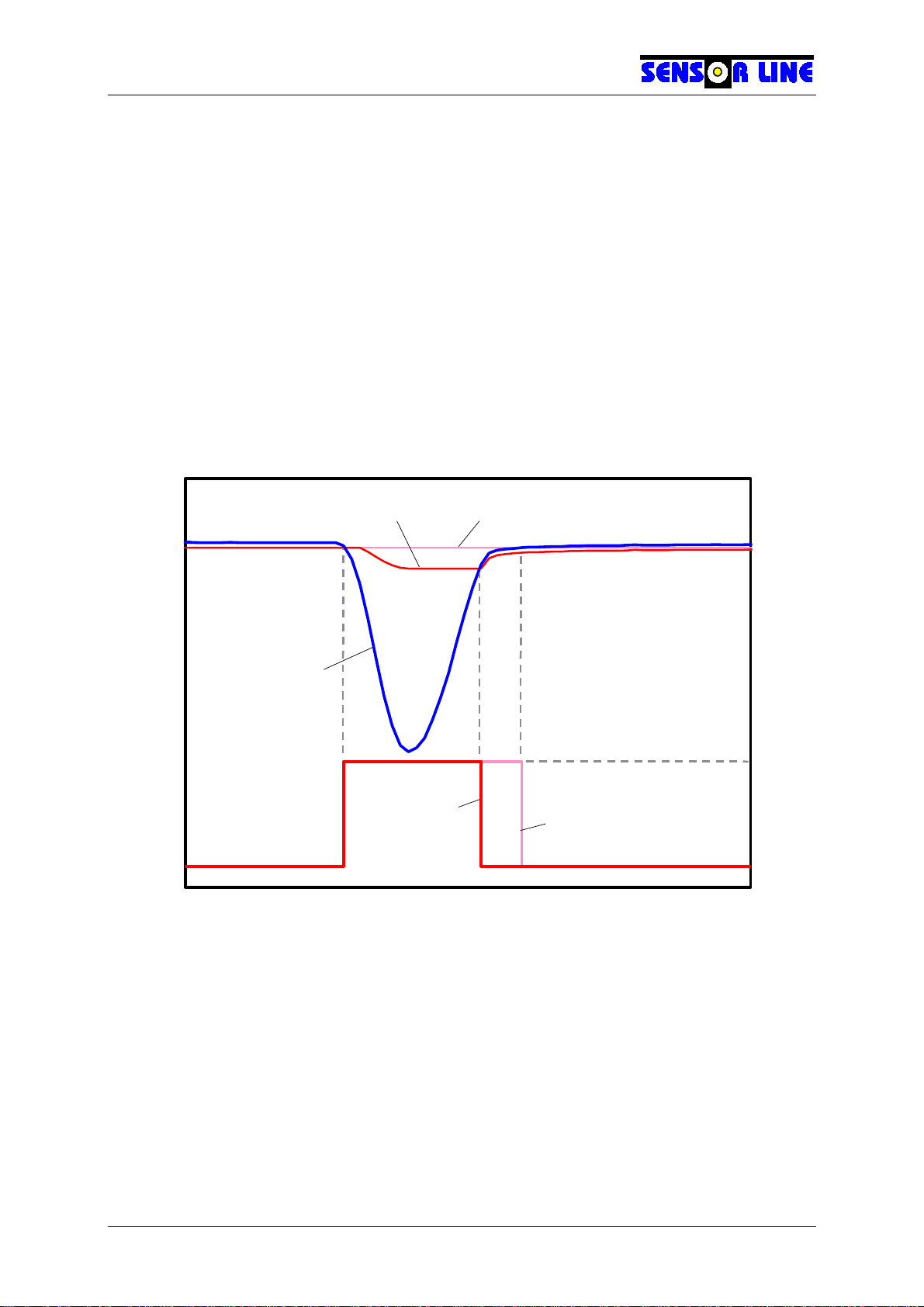
This issue is overcome by the adaptive threshold algorithm: After the trigger event has
happened the trigger threshold follows the sensor signal with a certain fraction of its
amplitude as long as the amplitude is growing, i.e. the sensor transmittance is decreasing.
When the sensor transmittance rises the threshold is held constant until the trigger state has
switched to OFF again. After that the threshold is held at a level below the sensor signal
which complies to the nominal threshold value according to section 3.2.3.2 as long as the
sensor transmittance is not decreasing again.
Time
Sensor Transmittance
Trigger Output State
100%
ON
OFF
Sensor Signal
Fixed ThresholdAdaptive Threshold
Output Pulse
with Adaptive
Threshold
Output Pulse
with Fixed
Threshold
Adaptive threshold processing can be switched on and off. The ratio of signal amplitude to
which the trigger threshold adapts can be defined to values of 50%, 25%, 12.5% and 6.25%.
Please refer to section 3.2.4 for instructions.
SL MD-220 User's Manual
- 19 -
3.2.4 SIL Switch and Jumper Settings
3.2.4.1 Switch Settings
Both boards have an 8-way SIL switch immediately behind the display LEDs. The particular
switches are numbered from 1 to 8 where switch 1 is the leftmost one. They are in on-
position when swiveled towards the front edge of the board i.e. towards the LEDs. Factory
setting is all switches off.
Switch Functions:
12345678
Adaptive Threshold
Enable
Adaptive Threshold
HI
Adaptive Threshold
LO
Trigger Threshold
HI
Trigger Threshold
LO
Baudrate
Select
High Speed
Enable
Enforce Minimum
Pulse Duration
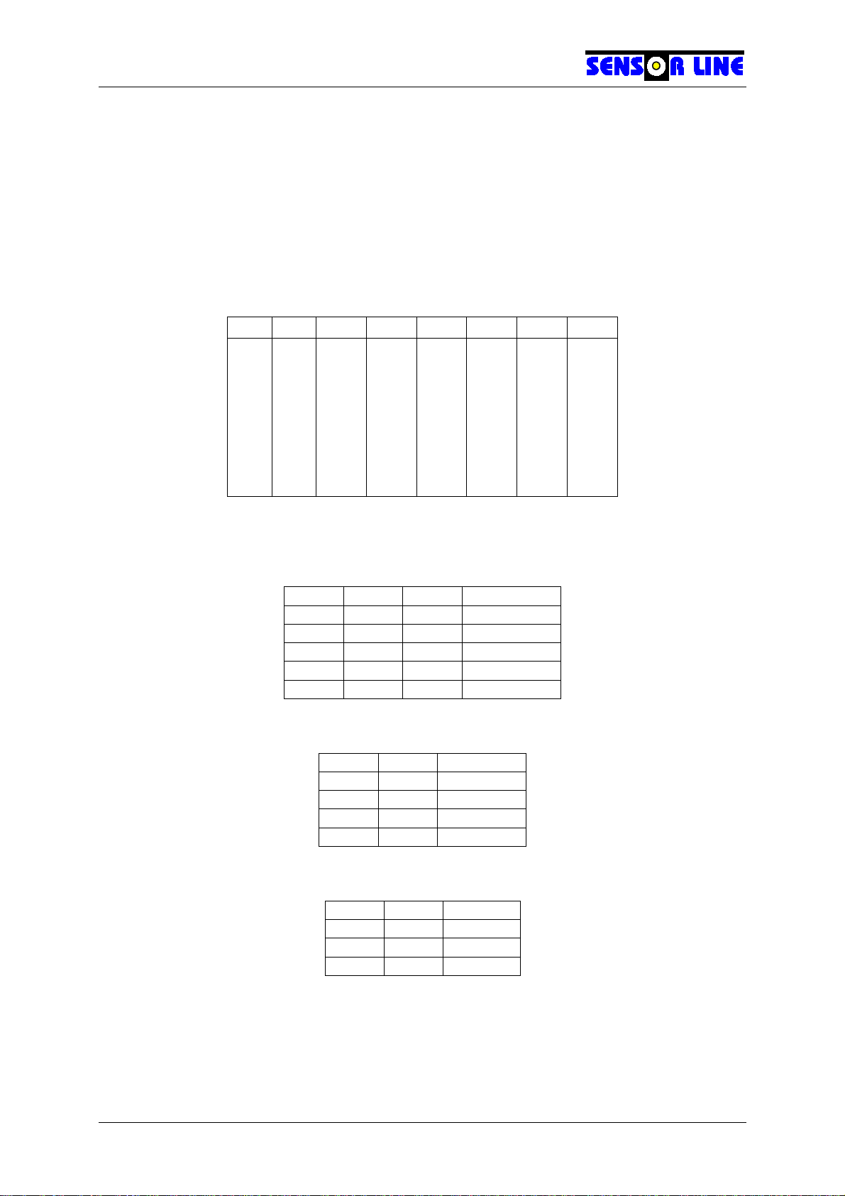
Switches 1-3 set the percentage to which the trigger off threshold follows an input pulse
(adaptive threshold, see section 3.2.3.3):
Way1 Way2 Way3 Percentage
off X X 0%
ON off off 6.25%
ON off ON 12.5%
ON ON off 25%
ON ON ON 50%
Switches 4 and 5 define the nominal trigger on threshold (see section 3.2.3.2):
Way4 Way5 Threshold
off off 0.8%
off ON 1.6%
ON off 0.2%
ON ON 0.4%
Switches 6 and 7 select the baud rate of the serial interface (see section 3.2.6.2):
Way6 Way7 Baud
off off 9600
ON off 19200
X ON 115200
When Switch 8 is in ON position the trigger output on time is forced to a minimum value
which depends from the setting of Jumper J1 (see below).

SL MD-220 User's Manual
- 20 -
3.2.4.2 Jumper Settings
When Jumper J1 is installed, the minimum trigger output on time is 40 ms, with J1 removed
it is 20 ms. This requires Switch 8 to be set to ON position (see above), otherwise the
configuration of J1 has no effect.
Jumper J2 is reserved for future use.
3.2.5 Status Outputs
The status outputs are the six status LEDs and four optocoupler outputs on the system
terminal block. In spite of the common labeling of some of them their behavior is not the
same. This might be confusing at first but provides maximum convenience during operation.
3.2.5.1 Status LEDs
There are three groups of status LEDs: TRGx, AUXx and ERRx. The TRGx LEDs show the
trigger status of both channels, the red ERRx LEDs report error conditions and the AUXx
show other conditions or events.
The TRGx LEDs correspond to one channel each. During initialization when the interface is
adjusting itself they are flashing up to ten times, giving a measure of the sensor loss (see
also paragraph 3.2.1 on page 16). They are on if the respective channel is ready to detect
load and go off when load a load is detected or when an error occurs.
The ERRx LEDs are also associated to one channel each. During initialization they are
flashing. If the controller cannot transmit enough light through a sensor the respective ERR
LED is switched on continuously.
The AUX1 LED is on when both channels are detecting load, otherwise it is off.
The AUX2 LED comes on when either of the channels has an error condition and its ERR
LED is on continuously. This might seem redundant, but the AUX2 LED is switched on and
off in accordance with the AUX2 optocoupler output which reports an error (see below). This
is convenient for troubleshooting purposes.
3.2.5.2 System Terminal Block
The system terminal block has four optocoupler outputs, divided into two groups: TRGx and
AUXx. The TRGx outputs become conductive (ON condition) when there is load detected by
the respective channel. This is inverse to the TRGx LEDs!
The AUXx optocoupler outputs follow the AUXx LEDs. The AUX1 output comes on when
both of the TRGx outputs are on and the AUX2 output comes on when there is an error
condition regardless at what channel.
Table of contents


