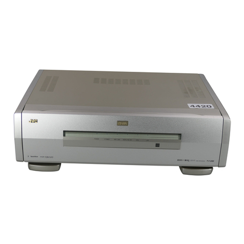
JVC SEA-E30B User manual

JVC
SERVICE
MANUAL
|
move.
SEA-E3OB
Contents
Safety
Precautions
........000
000
cee
1-1
1.
Specifications
........
ind
ramets
oneutcnie
:
pare
C2
2.
Service
Precautions
2-(1)
Prior
to
Servicing
Take
Special
Care
about
the
Following
Matters............200022.
13
2-(2)
Relation
between
Switch
Operation
anal
QUtpUt
ese
eee
wee
1-3
2-(3)
Parts
Replacement
.....
ee
Se
Pata
ie
alee
Lee
3.
Disassembly
3-(1)
Removal
of
the
Top
Cover
......
:
3-(2)
Removal
of
the
Front
Panel
.....
3-(3)
Removal
of
the
Analog
Switch
P.C.
B.
3-(4)
Removal
of
the
Power
Supply
P.C.B.
4.
Block
Diagram
.......
Sialet
dimes
:
5.
SEA-E30B
Schematic
Biscay.
RE
te
Ode
Parts
List
oc.
5
sees
ees
This
manual
combines
two
single
volumes;
Service
manual
and
Parts
list.
.
Separate-volume
Insertion
SEA-E30B
No.
2786
Dec.
1984

A-E30B
Safety
Precautions
1,
The
design
of
‘this
product
contains
special
hardware,
5.
Leakage
current
check
many
circuits
and
components
specially
for
safety
pur-
poses,
For
continued
protection,
no
changes
‘should
be
made
to
the
original
design
unless
authorized
in
writing
by
the
manufacturer.
Replacement
parts
must
be
identical
to
those
used
in
the
original
circuits.
Service
should
be
performed
by
qualified
personnel
only.
.
Alterations
of
the
design
or
circuitry
of
the
product
should
not
be
made.
Any
design
alterations
or
additions
will
void
the
manufacturer’s
warranty
and
will
further
relieve
the
manufacturer
of
responsibility
for
personal
injury
or
property
damage
resulting
therefrom.
.
Many
electrical
and
mechanical
parts
in
the
product
have
special
safety-related
characteristics,
These
charac-
teristics
are
often
not
evident
from
visual
inspection
nor
can
the
protection
afforded
by
them
necessarily
be
obtained
by
using
replacement
components
rated
for
higher
voltage,
wattage,
etc.
Replacement
parts
which
have
these
special
safety
characteristics
are
identified
in
the
parts
list
of
Service
manual.
Electrical
components
having
such
features
are
identified
by
shading
on
the
schematics
and
by
(
A\
)
on
the
parts
list
in
Service
manual.
The
use
of
a
substitute
replacement
which
does
not
have
the
same
safety
characteristics
as
the
recom-
mended
replacement
part
shown
in
the
parts
list
in
Service
manual
may
create
shock,
fire,
or
other
hazards.
.
The
leads
in
the
products
are
routed
and
dressed
with
ties,
clamps,
tubings,
barriers
and/or
the
like
to
be
separated
from
live
parts,
high
temperature
parts,
mov-
ing
parts
and/or
sharp edges
for
the
prevention
o
electric
shock
and
fire
hazard.
When
service
is
required,
the
original
lead
routing
and
dress
should
be
observed,
and
they
should
be
confirmed
to
be
returned
to
normal,
after
re-assembling.
Continental
Europe.)
Before
inserting
the
power
plug,
please
check
this
setting
to
see
that
it
corresponds
with
the
line
voltage
in
your
area.
If it
doesn’t,
be
sure
to
adjust
the
voltage
selector
switch
to
the
Lioy
20V
Proper
setting
before
operating
this
equipment.
The
voltage
selector
switch
is
located
on
the
yay
240V
=
rear
panel,
sae
VOLTS
CAUTION:
Before
selecting
the
“Voltage
selector
switch”
to
proper
voltage,
disconnect
the
ae
power
plug.
1-1
(No,
2786)
CHECKING
YOUR
LINE
VOLTAGE
(Except
for
U.S.A.,
Canada,
Australia,
U.K.
and
(Safety
for
electrical
shock
hazard)
After
re-assembling
the
product,
always
perform
an
isolation
check
on
the
exposed
metal
parts
of
the
Products
(antenna
terminals,
knobs,
metal
cabinet,
screw
heads,
headphone
jack,
control
shafts,
etc.)
to
be
sure
the
product
is
safe
to
operate
without
danger
of
electrical
shock.
Do
not
use
a
line
isolation
transformer
during
this
check.
@
Plug
the
AC
fine
cord
directly
into
the
AC
outlet,
Using
a
“Leakage
Current
Tester”,
measure
the
leakage
current
from
each
exposed
metal
part
of
the
cabinet,
particularly
any
exposed
metal
part
having
a
return
path
to
the
chassis,
to
a
known
good
earth
ground.
Any
leakage
current
must
not
exceed
0.5
mA
AC
(r.m.s.).
@
Alternate
check
method
Plug
the
AC
line
cord
directly
into
the
AC
outlet,
Use
an
AC
voltmeter
having
1,000
ohms
per
volt
or
more
sensitivity
in
the
following
manner.
Con-
nect
a
1500
{2
10
W
resistor
paralleled
by
a
0.15
pF
AC-type
capacitor
between
an
exposed
metal
part
and
a
known
good
earth
ground.
Measure
the
AC
voltage
across
the
resistor
with
the
AC
voltmeter.
Move
the
resistor
connection
to
each
exposed
meta!
Part,
particularly
any
exposed
metal
part
having
a
return
path
to
the
chassis,
and
measure
the
AC
voltage
across
the
resistor.
Now,
reverse
the
plug
in
the
AC
outlet
and
repeat
each
measurement.
Any
voltage
measured
must
not
exceed
0.75
V
AC
(r.m.s.).
This
corresponds
to
0.5
mA
AC
(r.m.s.).
AC
VOLTMETER
(Having
1000
ohms/volt,
or
more
sensitivity.
)
Place
this
probe
15000
10W
“on
each
exposed
metal
part.
Good
Earth
Ground

SEA-E30B
1.
Specifications
Input
section
SEA
input
:
Input
impedance
47
kohms
Tape
input
:
Input
impedance
47
kohms
Output
section
SEA
output
:
Output
impedance
300
ohms
Tape
REC
:
Output
impedance
300
ohms
(during
SEA
recording)
Rated
output
:
1
V
RMS
(with
SEA
system
flat)
Maximum
output
:
4.5
V
RMS
(with
SEA
system
flat,
0.5
%)
Total
harmonic
distortion
:
0.1
%
(20
Hz
—
20
kHz,
rated
output)
Gain
:
0
dB
with
SEA
button
ON
(SEA
system
flat)
Frequency
response
:
10
Hz
—
50
kHz
(+0,
-2
dB)
S/N
ratio
:
110
dB
(at
rated
output,
IHF
A-network
short-circuited)
Control
section
SEA
center
frequencies
:
31.5
Hz,
63
Hz,
125
Hz,
250
Hz,
500
Hz,
1
kHz,
2
kHz,
4
kHz,
8
kHz,
16
kHz
SEA
control
range
>
£10
dB
General
Power
source
:
See
attached
table
Dimensions
:
59(H)
x
340(W)
x
265(D)
mm
(2-5/16”
x
13-3/8"
x
10-7/16"')
Weight
:
1.7
kg
(3.7
Ibs)
Accessory
:
2
pairs
of
one-touch
signal
cords
(11
cm)
Note:
IHF:
Initials
of
the
Institute
of
High
Fidelity
in
the
U.S.A.
Design
and
specifications
subject
to
change
without
notice.
POWER
SPECIFICATIONS
ba
—
-
Areas
|
Power
Supply
Power
Consumption
Power
Outlet
Buss
ne)
j
QMF51U2-R20
U.S.A.
&
Canada
AC
120
V©,
60
Hz
6
watts
Fitted
(0.2
A
—
250
V)
zl
|
:
QMF51A2-R20S
Europe
AC
220
V~,
50
Hz
8
watts
Not
Fitted
(T
200
mA)
:
QMF51E2-R20SBS
ULK.
AC
240
V~,
50
Hz
8
watts
Not
Fitted
(T
200
mA)
be
|
. :
QMF51
A2-R20S
Australia
AC
240
Vv,
50
Hz
8
watts
Not
Fitted
(T
200
mA)
AC
110
V—120
V
U.S.
Military
Market
&
one
V
—
240
Vv
f
8
watts
Not
Fitted
QMF51A2-R20S
Other
Areas
selectable,
50/60
Hz
(T
200
mA)
|
(No.
2786)
1-2

A-E30B
2.
Service
Precautions
2-(1)
Prior
to
Servicing
Take
Special
Care
about
the
Following
Matters
1.
Parts
marked
with
A\
symbol
on
the
circuit
diagram
and
parts
list
are
important
for
safety.
When
replacing
those
parts,
be
sure
to
use
the
specified
parts
numbers.
2.
Confirm
that
all
metallic
clamps
are
covered
with
vinyl
tubes,
3.
Confirm
the
thickness
of
newly
replaced
wire’s
insulat-
ing
film
(0.3
mm
and
more).
4.
When
the
power
cord
is
replaced,
the
new
one
does
not
come
out
if
it
is
pulled
in
all
different
directions.
2-(2)
Relation
between
Switch
Operation
and
Output
TAPE
MONITOR
TAPE
REC
TERMINAL
‘OUT’
5.
Parts
relating
to
the
power
source
and
wires
have
been
bound
up
and
soldered.
6.
After
completion
of
soldering
parts
between
terminals
of
the
AC
power
fine,
confirm
that
there
remains
space
and
distance
more
than
3mm
between
neighboring
parts.
Pay
special
attention
to
solder’s
quantity,
bend
and
burr
of
wire.
LINE
OUT
TERMINAL
‘OUT’
LINE
IN
signal
LINE
IN
signal
SEA
et
ben
Moin
cles
ed
Operative
SEA
ON/OFF
.......
Operative
LINE
IN
signal
TAPE
playback
SB
Aree
el
ol
gee
6
Operative
SEA
ON/OFF
......
Inoperative
2-(3)
Parts
Replacement
1.
This
model
is
composed
of
the
parts
shown
in
the
dia-
gram
of
details
on
page
1-4,
“Disassembly”.
As
all
board
assemblies
are
fixed
to
the
chassis
with
screws,
refer
to
the
section
of
“Disassembly’’
when
disassemble
and
re-assemble
this
set.
2.
LEDs
built
in
SEA
volume
control
levers
can
be
removed
as
shown
in
the
figure
below.
If
one
of
LEDs
(for
a
block
of
right
or
left)
is
set
with
reverse
polarity
or
in
open
circuit,
all
LEDs
do
not
light,
As
adjoining
LEDs
are
set
with
reverse
polarity
alternate-
ly,
take
special
care
about
it
when
replacing
LEDs.
When
placing
an
order
for
a
single
LED,
specify
the
parts
number
of
AA3422K.
1-3
(No.
2786)
[How
to
distinguish
a
defective
LED
from
normal
ones|
aa
\
=e
Pull
an
LED
slightly
forward
1—2
mm,
and
make
a
short-
circuit
at
its
both
lead
wires.
if
other
4
LEDs
light
in
this
state,
the
LED
is
defective.
Operation
lever
Cathode
ey
(shorter
lead)
SEA
knob
Anode
(longer
lead)
SEA
volume

|
SEA-E30B
3.
Disassembly
3-(1)
Removal
of
the
Top
Cover
3-(3)
Removal
of
the
Analog
Switch
P.C.B.
1.
Remove
four
screws
@
on
both
sides.
1.
Remove
two
screws
@
fixing
the
pin
jacks
from
the
rear
2.
Remove
two
screws
@
of
the
rear
panel.
panel.
3.
Lift
up
the
rear
side
and
pull
out
the
top
cover
from
the
front
panel.
3-(4)
Removal
of
the
Power
Supply
P.C.B.
1.
Remove
two
screws
@
fixing
the
P.C.B.
3-(2)
Removal
of
the
Front
Panel
2.
Pull
out
the
push
shaft
from
the
power
switch.
1.
Pull
out
ten
SEA
slide
knobs.
2.
Remove
three
screws
@
fixing
the
front
panel
from
the
bottom.
3.
Pull
out
two
plastic
rivets
@
fixing
the
equalizer
P.C.B.
4.
Remove
the
P.C.B.
from
the
click
points
(eight
at
the
top
and
bottom)
fixing
it
to
the
front
panel.
Top
cover
Equalizer
P.C.B.
Front
panel
Push
shaft
a
Bx,
-
ye
Se
een
a
“Pe
ee
SEA
slide
knob
(No.
2786)
1-4

4-E30B
4.
Block
Diagram
!
1C202
NO
MN4O16B
+
|
|
|
oa
re
!
5-element
“elemen
|
LINE
|
aay
equalizer
IC
equalizer
IC
i
OUT
(©)
|
VR301
|
SEA
|
RECO}
VR
~
310
TAPE
|
1¢201
SQ
TAPE_MONI
SEA
I
PLAY
(O
7
O—anaoten
SYS)
St!
—2
@
+
{0311
|
|
<>
cS
|
$302
$301
;
|
|
Indicator
1
|
ewer
ee
ee
ee
ee ee
ee
ee
ee
ee
ee
oe
oe
Om
ee
we
ee
ee
ow
ow
oo
—_
—_—
re
ee ee
ee
wen
ee
wee
reer
ore
eee
ee
ee
aes
|
IR-CH
r
|
Same
as
the
block
diagram
for
the
L-ch
I
|
Ua
Sry
ne
eee
te
he
ce
aig
LA3600
Voo
GND
Vcc
OUT
MN4016B
wer
rr
er
rrr
5
we
ee
ee
ee
Ee
L0)--@)--@---@-
BASE]
NF1
BASE2
NF2
BASE3
NF3
BASE4
NFS
1-5
(No.
2786)

SEA-E30B
5.
SEA-E30B
Schematic
Diagram
cE
|
Lanta
2
(28
e201
|
R2II
i
1c202
2505644
(Q,R)
|
220
MN4OI68
On
p22
2
z
i
|
470K
R221
]R220
|
Rees
S|
P
|
100K!470K
:
|
pee
|
380°
2
Rse83
201
|
|
4
|
100
i
|
+
5
I
+
|
0203
i
’
|
=e
1S2076-31
coor
|
|
t
+
47y/25V
=
47}
|
eee
Sei
S202
e208
S20.
KF
OOP
D204 toot
1$2076-
31
|
|
4
4
Sah
|
bee
ee
ee
ere
lh
=
~
——
;
:
5
P|
|
|
od
fel}
0802
|
|
|
ROQIEBS
i
Teg
ac
ae
we
eae
|
|
|
=z.
i
|
{
1
i
WH
0803
|
ca
|
|
|
|
|
Freda
©
\220u/25V
for
bi
|
|
|
ca
es
{ |
|
el
F158
Cron
aa
|____asozea(r)
|="
A
ea
|
|
|
258562
se)
|
PTE]
|
|
___0804~
807
IIE2
Wigs
aver.
x
hot
gee
ar
ae
~
7
|
|
|
|
BH~O+S
HOTS
~2-~3-~D-B-—O+~TB
|
|
|
|
|
|
Ca33]
e328)
[C324]
|
less}
[C327
seh
|
|
|
\
eo
row
ete
AP
Ee
Pe
:
osoeL
sock
CAab
|
i
ceo7
|
7
“|
Big
MYT
PM)
rO
|
|
|
|
\
|
¢
4
eieacarre
f
eee
+
|
0.022]
9805
C351
mn
C347
C343
ge
C339
=
=
=
s+
ta
om
||
|
|
2.2y/50V
V41p/50V
[40.47%
}+0.22n
1+
RP
¢333.]
c329
|
c325.]
c32i
e3i9
|
fesiz
[esis
|
|
|
|
[Ese
/50V}
/50V
|
M!
0,068)
0039(M)
OO18M)}
—
O.0LM)
|
o
|
|
i
|
[rn
Ben
Lage
Lis
Ee
Tee]
|
|
|
|
pepo
n@nags
|
ie
s
\
\
|
1.
\
i
|
fou
|
|
Si
Ls
ES
+
an
a
|
bese
Lae
LN
7”
Lae
Lee
|
|
aah
eels
de:
vrso3|a
|
vR30d8
R308)
|
|
VR3IOA)
«
|VR3O4A
VR308/A
|VR307/A
|VR306
|
(50
ygzole
VR303/0
A
IVR3OI/A
|
|
|
|
i
i
+
|
|
|
:
|
|
|
4
*
:
;
|
|
j
250KW)
250K
250K
W
pron
j250Kw
|
50K"
i
jee
ie
a
$n
pee
|
re
+
+
Hz]
[S00Hz]
[‘kHe
|
[2kHz
|
[4kHz
|
|
8kHz
|
[iekHe
|
05
{
|
0:
ve
SEES
at
2
z
i
|
i
[Sezem
(Power
sw]
fo
|
pe
oo
ELoiite
DH
ps
an
|
(
|
rea
ZV
|
|
ou
U
J
|
|
|
|
|
|
|
|
|
|
i
|
yogeaaM)
per
|
i
|
|
|
Ll
|
|
|
|
Cane
|
PUSH
ON
|
|
|
|
|
|
|
|
|
|
|
|
a]
|
Best
|
g
38
|
PRIMARY
FUSE
BLOCK
SHOULD
BE
CHANGED
|
Sf)
|
82-1
|
|
HOV
=
Ov
—
24
(D)
FOR
JAPAN
AC
{00V,
50/60
Hz
ee
EACH
DESTINATION
AS
SHOWN
IN
LEFT
AC
120V~
60Hz
AC
120V~
6OHz
«fac
220V
~~
,50Hz
>
eX)
|
e
|
.
3/8
{&
i
POWER
TRANS
POWER
TRANS
ETPIOO0-29L
4
le
a
ETE
GCQ
29
JA
BLK
/
WHITE
(uy)
FOR
OTHER
COUNTRIES:
AC
110-
120V/220-
240V~,
50/60Hz
(BS)
FOR
U.K
:
AC240V~
,
SOHZ
(G)
FOR
WEST
GERMANY
AC220V~
,50Hz|
(P}(PG)
FOR:
PACE
X
AC
110-
120V/220~
240V~
(A)
FOR
AUSTRALIA:
AC240V~
,
SOHZ
|
(£)
FOR
EUROPEAN
COUNTRIES:
AC220V~
,S0Hz|
(©)
FOR
CANADA
+
AC
120V
~
»
6OHz
(FOR
U.S.A
+
AC
120V~
,
6OHz
50/60HZ
lshows
DC
voltage
to
the
chassis
with
no
signal
in-
5.
When
replacing
the
parts
in
the
darkened
area
(
put.
and
those
marked
with
/\
,
be
sure
to
use
the
designated
indicates
positive
B
power
supply.
parts
to
ensure
safety.
indicates
negative
B
power
supply.
6.
This
is
the
standard
circuit
diagram.
indicates
signal
path.
The
design
and
contents
are
subject
to
change
without
notice.
(No,
2786)
1-6

PARTS
LIST
Contents
1.
Exploded
View
and
Part
Numbers
2.
Printed
Circuit
Board
Ass’y
and
Parts
List
2-(1)
ENF-016
0
3.
Packing
Materials
4.
Accessories
List
SEA
Amplifier
P.C.
Board
Ass’y
and
Part
Numbers
NN
ff
KD
SEA-E30B
(No.
2786)
2-1

A-E30B
1.
Exploded
View
and
Part
Numbers
2-2
(No.
2786)
Note:
Those
items
shown
on
the
disassembly
diagram
without
indication
of
reference
Nos.
are
supplied
as
assembly
parts.

SEA-E30E
|
A:
Safety
Parts
The
Marks
for
Designated
Areas
U.S.A.
Canada
U.S.
Military
Market
Europe
West
Germany
Other
Countries
Part
Number
Part
Name
Q'ty
Description
1
EFP-SEAE30
Front
Panel
Ass’y
1
E70912-001
JVC
Mark
1
2
E70851-001
Slide
knob
10
3
E71716-001
Push
Button
2
TAPE
MONITOR,SEA
4
SLR-55VC50F
L.E.D.
1
5
QSP0301-006
Push
Switch
2
|
TAPE
MONITOR,
SEA
6
QVZ5311-001
Variable
Resistor
10
7
a =
=
_
=
8
E48729-007
Plastic
Rivet
2
9
E24008-007
Metal
Cover
|
1
10
E61660-004
Specia!
Screw
4
11
SHSB3008M
Screw
i;
2
12
EMNOOTV-402A
4P
Pin
Jack
2
TAPE,
LINE
13
E24841-003
1
Rear
Panel
1
E,G
|
E24841-004
Rear
Panel
1
|
A,
BS
E24841-005
Rear
Panel
14
P,
PG,
U
E24841-006
Rear
Panel
1
J,c
14
SBSB3008M
Tapping
Screw
2
15
SDSB3008M
Tapping
Screw
i
2
AC
Outlet
Al
16
QHS3876-162
Cord
Stopper
Is
1
J,C,P,PG,£,A,G,U
A
|
QHS3876-162BS
Cord
Stopper
=
BS
Z\}
17
QMP
1200-200
Power
Cord
1
J
A|
QMP
1340-200
Power
Cord
1
c
A
QMP2560-244
Power
Cord
4
A
A
QMP3900-200
Power
Cord
1
E,G
A
QMP7600-250
Power
Cord
hi
4
P,PG,
U
A
OMP9017-008BS
Power
Cord
1
BS
A|
18
QMC0440-001
AC
Outlet
1
Cc
A
QMC0437-002
AC
Outlet
1
J
A|
19
QMF51A2-R20S
Fuse
1
P,PG,E,
A, G,
U
A
QMF51E2-R20SBS
Fuse
1
BS
A
QMF51U2-R20
Fuse
1
J,C
A|
20
ETP1000-29EBBS
Power
Transformer
1
BS
A
ETP1000-29EB
Power
Transformer
1
E,A,G
A
ETP1000-29JA
Power
Transformer
1
iC
A
ETP1000-29LA
Power
Transformer
1
/
PPG,
U
21
OST4101-E14
Power
Switch
1
4
POWER
22
E71712-002
Push
Shaft
1
POWER
23
E67628-002
Push
Button
4
POWER
24
E68587-003
Bracket
1
25
SBSB3008N
Tapping
Screw
|
8
26
E24843-001
Chassis
Base
1
27
SHSB3008N
Screw
1
28
SBSF30082
Tapping
Screw
2
29
E47227-021
Foot
4
|
30
Y¥
40434-019
Spacer
1
31
EMG7331-001
Fuse
Clip
2
32
OQSS8A22-E01
Voltage
Selector
1
P,
PG,
U
33
E65119-004
Special
Screw
2
Voltage
Selector
P,PG,U
34
GBSB3008N
Tapping
Screw
2
E69589-002
Spacer
1
AC
Outlet
(No.
2786)
2-3
|

A-E30B
2.
Printed
Circuit
Board
and
Parts
List
2-(1)
ENF-016
0
SEA
Amplifier
P.C.
Board
Ass’y
Note:
ENF-016
C
varies
according
to
the
areas
employed.
See
note
(1)
when
placing
an
order.
Note
(1)
|
P.C.
Board
Ass‘y
|
Designated
Areas
r
mers
|
|
ENF-016
[BJ]
|
USA,
;
a
Paoet
|
{
|
ENF-016
|CBS|
|
ULI.
cant
i
|
ENF-016
[BD]
|
Europe
|
ENF-016
(E}
|
ULS.
Military
Market
&
Other
Countries
4
|
ENE-016
[F]
|
West
Germany
|
f
ES
my
eee
|
ENF-016
(G
|
Canada
i
|
ENF-016
[H]
|
Australia
Each
Individuai
P.C.
Board
Location
|
DENFO16-1
Power
Supply
P.C.
Board
Ass’y
ss
@
ENF-016-2
@
Analog
Switch
and
Mute
P.C.
Board
Ass’y
ENF-016-3
SEA
Amp.
P.C,
Board
}
Ass’y
|
4
ENF016-4
|
AC
Outlet
P.C.
Board
Ass‘y
|
@ENF-016-5
Voitage
Selector
P.C.
|
Board
Ass’y
2-4
(No.
2786)

SEA-E30B
Transistors
Capacitors
aN
on
Part
Number
|
Description
Areas
A
ie,
Part
Number
Description
Areas
Maker
C310
=|
QCY31HK-271
270pF
|
SOV!
Ceramic
|
|
Q201
|
2SA564A(Q,R)
|
Silicon
|
Matsushita
C311
|
QFNSTHJ-682
|
G800pF
|
SOV)
Mylar
i
:
C312
|
QFN31HJ-682
6800pF
|
50V|
Mylar
Q202
25C1685
(O,
R)
Silicon
Matsushita
:
us
heat
C313
|
QCY21HK-101
100pF
|
SOV)
Ceramic
It
gee
pasoane
te}
Ree
fee
€314_
|
QCY31HK-101__|
100pF_|_50V|
Ceramic
i
Qgo2
|
258562
{C)
Silicon
|
Hitachi
4
1
C315.
|
QEK61CM-226
|
22uF
16V]
Electro
|
|¢316
|
QEK61CM-226
|
22uF
16V|
Electro
C317.
|
QEK61CM-226
|
22uF
16V|
Electro
ICs
C318
|
QEK61CM-226
|
22uF
16V|
Electro
|
C319
|
QFN31HJ-472
4700pF
|
50V|
Mylar
fT
tem
ea
H
'¢320.
|
QEN31HJ-472
4700pF
|
50V]
Mylar
A}
No.
Bere
Number
Decpnan
ola
1321
|
QFN31HJ-103
|
0.01uF
|
50V/
Mylar
Maker
|
C322.
|
QFN31HJ-103
0.01uF
|
SOV)
Mylar
C323
|
QCY31HK-471
470pF
|
5OV/
Ceramic
10207"
(4
MINGOTRE
pee
Matsushita
|
C324
|
QCY31HK-471__|
470pF_|
_50V|
Ceramic
|
oe
eee
be
ae
|
C325
|
QFNSIHJ-183
|
0.018uF/
50V|
Mylar
eet
ease
ie
leane
|
|
|
|
6326
|
QFN31HJ-183
0.018uF}
50V|
Mylar
Lresag
ML
AaEOO
te
ae
|
|
C327.
|
QFN31HJ-102
1000pF
|
S50V|
Mylar
ee
i
|
C328
|
QFN31HJ-102
1000pF
|
50V!
Mylar
,
1304
|
LA3600
H.C,
,
Sanyo
;
|
C329
|
QFN31HJ-393
|
0.039uF
|
50V/
Mylar
|
|€330
|
QFN31HJ-393
|
0.039uF!
S5OV/
Mylar
|
'
C331
|
QFN31HJ-182
1800pF
|
SOV]
Mylar
Diodes
|
1332
|
QFN31HJ-182
|
1800pF
|
50V|
Mylar
|
|C333
|
QFN81HJ-683
0.068uF|
50V]
Mylar
ans
=
I
C334
|
QFN31HJ-683
0.068uF|
50V|
Mylar
Al
No.
Part
Number
Description
C335.
|
QFN31HJ-392
3900pF
|
50V|
Mylar
es
ee
smaLaE
C336
=|
QFN31HJ-392
3900pF
|
50V|
Mylar
C337
|
QFN31HJ-154
0.15uF
|
50V|
Mylar
D201
|
RDS.6EB3
Zener
NEC
C338
|
QFN31HJ-154
0.15uF
|
50V|
Mylar
D202
|
182076-31
Silicon
|
Hitachi
C339
|
QEK61HM-224
|
0.22uF
|
S50V|
Electro
D203
|
182076-31
Silicon
|
Hitachi
[C340
|
QEK61HM-224
|
0.22uF
|
50V|
Electro
D204
|
1S2076-31
Silicon
|
Hitachi
C341
|
QFN31HJ-183
0.018uF|
50V|
Mylar
_
|
205
|
Mc921
Silicon
|
Ryoyo
C342
|
QFN31HJ-183
|
:0.018uF|
50V/
Mylar
|
|
p206
|
Mc911
Silicon
|
Ryoyo
C343.
|
QEK61HM-474_
|
0.47uF
|
50V|
Electro
|
|
D311
|
SLR-SSVC50F
L.E.D.
|
Rohm
|
|
C344
|
QEK61HM-474
|
0.47uF
|
50V|
Electro
gh
; ;
D802
|
RDY.1EB3
|
Zener
|
NEC
i
QFN31HJ-393
|
0.039uF|
50V|
Mylar
|
|
|
D803
|
RD9.1EB3
|
Zener
|
NEC
|
|
C346
|
QFN31HJ-393
0.039uF|
50V|
Mylar
|,
804
|
1162
|
Silicon
|
Nippon
Inter
|
|
|
|
C347
|
QEK61HM-105
|
1uF
50V|
Electro
[|
p805
|
1162
Silicon
|
Nippon
Inter
|
C348
«|
QEK61HM-105
|
1nF
50V|
Electro
|
i
|
9806
|
11€2
Silicon
|
Nippon
Inter
|
C349
|
OQFN81HJ-683
0.068uF|
5OV|Mylar
|
D807
|
11E2
Silicon
Nippon
Inter
|
C350
QFN81HJ-683
0.068uF|
50V|
Mylar
L
*
S
[C351
|
QEK61HM-225
|
2.2uF
|
50Vj
Electro
|
|
C352
|
QEK61HM-225
|
2.2uF
|
50V/
Electro
|
|}
C353
|
QFN31HJ-124
0.12uF
|
50V!
Mylar
Capacitors
C354
|
QFN81HJ-124
0.12uF
|
50V|
Mylar
~
4
[C355
|
QETBIEM-476
|
47uF
25V|
Electro
|
A
Ne
Part
Number
Description
Areas
C356
QEK61EM-476
47
uF
25V/
Electro
:
=
r
|
|¢357.
|
QCY21HK-101
100pF
|
SOV]
Ceramic
C201
QETC1EM-476
47uF
25V
|
Electro
|
C358
QCY21HK-101
100pF
|
SOV)
Ceramic
C202
QETC1EM-476
47
uF
25V
|
Electro
C359
QCY21HK-101
100pF
50V|
Ceramic
|
C203.
|
QETCIEM-476
|
47uF
25V
|
Electro
fc360
|
QCY21HK-101
100pF
|
S5OV|
Ceramic
C204
|
QCY31HK-101
100pF
|
50V|
Ceramic
C801
|
QETB1CM-228
|
2200uF
|
16V/
Electro
C205
|
QCY31HK-101
100pF
|
50V|
Ceramic
H
C802.
|
QETB1CM-228
|
2200uF
|
16V|
Electro
C206.
|
QCY31HK-101
100pF
|
50V|
Ceramic
C803.
|
QETC1EM-227_
|
220uF
|
25V/
Electro
C301
QEK61HM-475)
|
4.7uF
|
50V|
Electro
C804
|
QETC1EM-227_
|
220uF
|
25V|Electro
|
C302.
|
QEK61HM-475
|
4.7uF
|
50V/
Electro
|
C805
|
QEN31HJ-223
0.022uF|
50V|
Mylar
C303
|
QETBIEM-106
|
10uF
25V
|
Electro
|
|
C806
|
QCF31HP-223
|
0.022uF|
50V|
Ceramic
|
|
€304_
|
QEKG1EM-106
|
10uF_|
_25V/
Electro
|
C807
|
QCF31HP-223
0.022uF
|}
50V!
Ceramic
FT
¢305
|
QEK61CM-226
|
22uF
16V/|
Electro
C808
|
QCF31HP-223
0.022uF}
SOV]
Ceramic
C306
|
QEK61CM-226
|
22uF
16V
|
Electro
=
|
|
¢307
|
QCY31HK-101
100pF
|
50V|
Ceramic
C308
«|
QCY31HK-101
100pF
|
50V|
Ceramic
|_|
©309
|
QCY21HK-271__|
270pF
|
50V|
Ceramic
(No.
2786)
2-5
3

A-E30B
Resistors
Others
aN
iy
Part
Number
Description
Areas
AN
eel
Part
number
Description
Areas
R201
QRD141J-101S
100
2
|1/4W|Carbon
E11058-102
Circuit
Board
B
R202
QRD141J-563S
56kQ
|1/4
W
{Carbon
E11058-102
Circuit
Board
G
R203
QRD141J5-563S
56k2
|1/4
W
|
Garbon
E11058-202
Circuit
Board
D
R204
QRD141J-153S
15kQ
{1/4
W
|Carbon
£11058-202
Circuit
Board
E
|
R205
QRD141J-824S
|
820
k2.|1/4
W
|
Carbon
£11058-202
Circuit
Board
F
R206
QRD141J-824S
820
k}1/4
W
|
Carbon
E£11058-202
Circuit
Board
H
R207
QRD141J-824S
820
k2/1/4
W
|
Carbon
£11058-202BS
Circuit
Board
CBS
R208
QRD141J-221S
220
2
|1/4
W
|
Carbon
QMC0437-002
AC
Socket
R209
QRD141J5-221S
220
Q
|1/4W
|Carbon
QMC0440-001
AC
Outlet
R210
QRD141J-221S
220
2
(1/4
W
|Carbon
£65508-002
Tab
R211
QRD141J-221S
|
220
2
|1/4
W
|
Carbon
EMG7331-001
Fuse
Clip
R212
QRD141J-221S
220
2
{1/4
Wj
Carbon
EMG7331-001
Fuse
Clip
|
R213
QRD141J-221S
220
2
|1/4
W
|
Carbon
J201
EMNOOTV-402A
|
Pin
Jack
Assy
|
R214
QRD141J-221S
220
2
|1/4W
|
Carbon
J202
EMNOOTV-402A
Pin
Jack
Assy
|
R215
QRD141J-221S
|
2209
|1/4
W
|Carbon
|
$301
QSP0301-006
Push
Switch
R216
QRD141J-221S
220
2
|1/4
W
|Carbon
$302
|
QSP0301-006
Push
Switch
R217
QRD141J-221S
220
Q
|1/4
W
|
Carbon
A|
$501
QSS8A22-E01
Voltage
Selector
R218
QRD141J-474S
470
k2}1/4
W
|
Carbon
$801
QST4101-E14
i
Push
Switch
|
R219
QRD141J5-474S
470
kQ|1/4
W
|
Carbon
A|
T7801
ETP1000-29EA
Power
Transformer
D
{R220
|
QRD141J-474S
470
k2|1/4
W
|
Carbon
A|
T801
ETP1000-29EA
Power
Transformer
ee
R221
QRD141J-104S
100
k2|1/4
w|
Carbon
|
1A;
T801
ETP1000-29EA
Power
Transformer
H
R222
QRD141J-474S
|
470k2/1/4W
Carbon
|
|
A}
T801
ETP1000-29EABS
|
Power
Transformer
CBS
R223
QORD141J5-474S
=|
470
kQ!1/4
W
|
Carbon
\
A}
T801
ETP1000-29JA
Power
Transformer
B
R224
QRD141J-474S
470
kQ|1/4
W
|
Carbon
i
A}
T801
ETP1000-29JA
Power
Transformer
G
R225
QRD141J-104S
100
k2Q|1/4
W}
Carbon
A}
T801
ETP1000-29LA
Power
Transformer
E
R305
QRD141J-562S
5.6
kQ
|1/4
W
{Carbon
A\
:
Safety
Parts
R306
QRD141J5-562S
5.6
kQ
|1/4
Wj
Carbon
R307
QRD141J-102S
1kQ
=
|1/4W
{Carbon
R308
QRD141J-471S
470
2
11/4
W|Carbon
R309
ORD141J-471S
470
2
1/4W
R310
|
aRD141J-473S_
|
47kQ
Carbon
R311
|
ORD1414-473S_
|
47kQ
|1/4W
{Carbon
R801
|
QRD141J-152S
|
1.5k2|1/4W
|
Carbon
R802
|
QRD141J-152S
|
1.52
|1/4W
{Carbon
|__R803_|
ORD1414-5625_|
5.6
kx
|1/4
W
[Carbon
R803
|
ORD141J-562S_
|
5.6
k2
11/4
W]
Carbon
R803
QRD141J-562S
5.6
kQ
{1/4
W|
Carbon
VR301
QV25311-001
250
kQ
Variable
VR302
|
QVZ5311-001
250
kQ
Variable
I
VR303
|
QV2Z5311-001
250
kQ
Variable
VR304
|
QV25311-001
250
kQ
|
Variable
VR305
|
0VZ5311-001
250
kQ
Variable
VR306
|
QVZ5311-001
250
kQ
Variable
VR307
|
QVZ5311-001
250
k2
Variable
VR308
|
0VZ5311-001
|
250
kQ
_|
Variable
VR309
|
0VZ5311-001
250
kQ
Variable
VR310
{
QV
Z25311-001
250
kQ
Variable
|
2-6
(No.
2786)

SEA-E30B
3.
Packing
Materials
and
Part
Numbers
Packing
Materials
Part
Name
Q'ty
Description
[
No.
Part
Number
1
PK-SEAE30E(B)
2
|
N2Z-SEA30
3
|
€302688-010
E302688-010B
Packing
Case
1
Fillers
2
Protect
Sheet
1
Protect
Sheet
1
(E24857-001)
J,C,P,PG,A,E,G,U
BS
The
Marks
for
Designated
Areas
ecient
ef
el
keghan
We
U.S.A.
Cat
ae
cote
aint
ins
Canada
PUPG
6
he
GG
U.S.
Mititary
Market
Bo
esc
itched
&
ea
Europe
Geel
Sk
ee
a
West
Germany
BS
Aaa
Maa
sales
ULK.
hg
late
ue
ces
G8:
8
Other
Countries
Part
Number
Part
Name
Area
E30580-1214A
E30580-1214ABS
BT20048B
BT20025H
BT20029C
Instruction
Book
Instruction
Book
Warranty
Card
Warranty
Card
Warranty
Card
J,C,P,PG,A,E,G,
U
BS
J,P,PG
Cc
A
BT20060
BT
20064
BT20066
BT20071A
BT20054-006A
Warranty
Card
Warranty
Card
ECC
Agency
Service
Center
List
FTZ
Information
Card
BS
G
Cc
G
BT20046B
BT20044D
EWP307-002
E04056
E35497-022
Service
Information
Card
Safety
Instruction
Sheet
Signal
Cord
Siemens
Plug
Caution
Sheet
(220
V
—
240
V)
J,P,
PG
J
PG,
U
PG,U
E35497-021
E300196-033
E300196-033B
E66416-003
Caution
Sheet
(110
V
—
120
V)
Envelope
(for
Instruction
Book)
Envelope
(for
Instruction
Book)
Envelope
(for
Warranty
Card)
P
J,C,P,PG,A,E,G,U
BS
J
(No.
2786)
2-7
|
|
|
|
|
|
|
|
Other JVC Recording Equipment manuals

JVC
JVC BR-HD50U - Compact HDV/DV Format Video... Quick start guide

JVC
JVC HR-V610EX User manual

JVC
JVC XL-R5000BK User manual

JVC
JVC KM-IP6000 User manual
JVC
JVC XL-R5000BK User manual
JVC
JVC KD-G411 User manual

JVC
JVC XM-228BK User manual

JVC
JVC HM -DR10000EU User manual

JVC
JVC XL-R5020BK User manual
JVC
JVC HR-S5900EG User manual