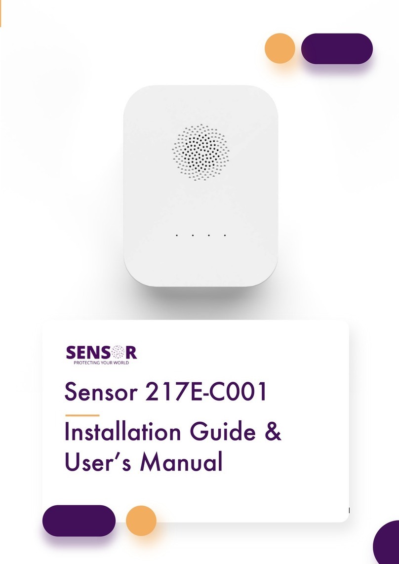
Sensor 217E-02 User manual

1
Sensor 217E-02
Smoke Alarm Manual

2
Specifications - Sensor 217E-02
Primary power source
AC(100 ~ 240)V
Secondary power source
DC 3V
Mains supply current limit
0.06A@230V, 0.12A@115V
Number of interconnected devices
24
Operating temperature
(0 ~ +55) °C
Operating humidity
(10 ~ 95) % RH, non-condensing
Storage temperature
(-25 ~ +80) °C
Storage humidity
(0 ~ 98) % RH, non-condensing
Complies with
AS3786:2014
Caution
This product must only be used for the purpose described in these instructions and must be
installed by a licensed electrician in accordance with the Building Code Australia (BCA) and local
and state wiring rules and regulations.
Product Limitations: Caution! This device does not detect heat, gas or flame, and should not be
covered with a guard or similar obstructing item.
This device may not alert people who are hearing impaired. It is strongly recommended that
special-purpose smoke alarms using visual or vibrating alerting devices be installed for occupants
with a hearing impairment.
This device may not be effective in fires where smoke is prevented from reaching the device (e.g.,
where intermediate doors are closed), where the fire grows so rapidly that the egress path is
blocked (even when correctly located), and where the fire is intimate to a person (e.g., where a
victim’s clothes catch fire).
Sleeping Occupants: Studies have shown that smoke alarms may not awaken all sleeping
occupants. It is the responsibility of individuals in the household who are capable of assisting
others to provide assistance to those who may not be awakened by the alarm sound, or to those
who may be incapable of safely evacuating the area unassisted.
Installation Limitations: This product is designed for use in a single residential unit, such as a family
home or apartment. Smoke alarms located outside the dwelling may not provide adequate
warning to occupants. This product is not designed for use in non-residential buildings. Non-
residential buildings require special-purpose fire detection and alarm systems. This product alone
is not a suitable substitute for a fire detection system installed in places of business or where
people sleep on a temporary basis, such as hotels, motels, dormitories, hospitals, nursing homes,
or group homes of any kind, even if they were once dwellings. Please refer to local and state
regulations for fire detection and alarm system requirements for non-residential buildings and
temporary accommodation settings.

3
Overview
SENSOR provides an online platform and ecosystem that allows 24/7 line of sight
for real estate property managers to monitor the compliance of their properties.
With round-the-clock monitoring without the need to physically visit the property,
SENSOR mitigates the risk of the unknown.
Using return pathway Internet of Things (IoT) devices installed at the property,
SENSOR provides real-time device updates to meet legislative requirements and
reduce the risk of property damage.
Achieve legislative compliance and enhanced tenant safety with SENSOR’s range
of smoke-detection sensors and alarms.
Introduction to the SENSOR 217E-02 Photoelectric Smoke Alarm
The SENSOR 217E-02 Photoelectric Smoke Alarm works as an independent or
interconnected photoelectric smoke alarm. When used in conjunction with the
SENSOR Hub, an intuitive return pathway is created giving users access to
monitoring, event logging, and remote testing via an IoT (Internet of Things)
connection housed within the SENSOR Hub.
Due to the advanced battery technology and low power consumption, each model
of alarm in the 217E-02 series can be used to satisfy either the 230V or 10 year
lithium requirement - depending on the applicable installation legislation or other
local or state requirements.
Each alarm connects to the SENSOR Hub independently of each other with a
range of up to 200m line of sight.
The 217E-02 model utilises a sealed lithium battery for both the operation of the
alarm and the RF interconnect to the hub, ensuring no battery replacements are
required over the life of the alarm.

4
The alarms are fitted with two test functions:
1. The test button on the face of the alarm can be used to test the alarm if
required.
2. The alarm is also fitted with a software-based test which can be
scheduled for a particular date and time or performed in real time via
the portal.
The alarms are also fitted with several additional functions to ensure
safety and compliance, including:
•Early low battery detection – designed to pre-empt a low battery alarm so it
can be replaced prior to low battery beeping.
•Tamper detection – to ensure the alarms are always closed and operating
correctly.
•RF disconnect warning – should an alarm become disconnected from the
network a notification will be sent via the portal.
•230V power outage – if power is lost to the alarm or hub a notification will
be sent via the portal.
Disclaimers
All electrical installations must be carried out by a qualified electrician, in accordance
with local regulations and Australian Standards.
It remains the duty of the installer to ensure that:
•All hardware is undamaged and in proper operating order,
•The correct number of alarms are being installed in compliant locations as per
the local requirements.
This product must only be used for the purpose described in these instructions and
must be installed by a licensed electrician in accordance with the Building Code
Australia (BCA) and local and state wiring rules and regulations.

5
Understanding Indicator and Alarm Signals
Smoke alarms produce the following indicator and alarm signals, depending on
their status condition.
Primary units
Sensor
217E-02
Quiescent condition
indication
Green LED continuously on, Red LED flashes every
40s
Low battery indication
Short audible signal every 40 secs, synchronized with
a single flash of the yellow LED for 30 days
Low battery hush
indication
Flashing yellow LED every 40 secs
Low battery hush time
10 hrs
Alarm Condition
Alarm condition audible
indication output
≥85 dB @ 3 mins three long beeps, repeating
Alarm condition visual
indication
Three blinks synchronized with audible alarm
Alarm condition hush
indicator
Device entering the alarm condition: Flashing red LED
every 1 sec
Alarm condition hush time
Smoke alarm: 8 mins
Test Condition
Test condition audible
indication output
≥85 dB @ 3 mins, two sets of three long beeps
Test condition visual
indication
The yellow LED flashes once, then the red LED flashes
three times in two cycles
Fault Condition
Smoke chamber fault
indication
Short audible signal every 40 secs, synchronized with
the yellow LED flashes three times
Smoke chamber fault hush
indication
Three flashes of the yellow LED every 40 secs
Smoke chamber fault hush
time
10 hrs

6
Wireless Interconnection
Group mode connection
indication on slave
device(s)
Flashing yellow LED every 1 sec followed by a short
audible signal
Interconnected Units
When configured as a group, interconnected units produce the following additional
indicator and alarm signal when the primary unit is operated.
Alarm Condition
Alarm condition audible indication
output
≥85 dB @ 3 mins, three long beeps,
repeating
Alarm condition visual indication
—
Test Condition
Test condition audible indication output
≥85 dB @ 3 mins, two sets of three long
beeps
Test condition visual indication
—
Fault Condition
Smoke chamber fault indication
Short audible signal every 40 secs

7
Installation Preparation
Equipment
Before commencing installation, ensure all equipment and tools to mount and test
the device are available, such as drills, mounting screws (supplied), cables, and
ladders.
Location Selection in Homes and Apartments
For complete coverage, alarms are to be installed in alignment with local, state,
and federal regulations. For enhanced coverage, alarms can be installed in all
rooms, halls, storage areas, basements, and attics in the dwelling. Please use the
following location guide.
Single Storey Dwellings
Install a smoke alarm in the hallway outside every separate bedroom area, as
shown in Fig. 1 a). Two smoke alarms should be installed in dwellings with two
bedroom areas, as shown in Fig. 1 b).
Fig. 1 a) – Single bedroom area
Fig. 1 b) – Multiple bedroom areas
Multi-Storey Dwellings
Install a smoke alarm on every floor of a multi-floor dwelling, as shown in Fig. 2.
MINIMUM ALARM LOCATIONS
ADDITIONAL ALARM LOCATIONS
ADDITIONAL ALARM LOCATIONS
MINIMUM ALARM LOCATIONS
BEDROOM
BED
ROOM
BED
ROOM
BED
ROOM
KITCHEN
FAMILY ROOM
LIVING ROOM
LIVING ROOM
BINING ROOM KITCHEN BED
ROOM
BED
ROOM
BEDROOM

8
Recommended Enhanced Safety
To improve early detection performance and safe evacuation, ensure that a
minimum of two alarms are installed per dwelling. Consider installing additional
alarms as follows:
•Inside every bedroom
•At both ends of a bedroom hallway if the hallway is more than 12 m
•Inside every room where one sleeps with the door partly or completely closed,
since smoke could be blocked by the closed door, and a hallway alarm may not
wake up the sleeper if the door is closed
•At the bottom of the basement stairwell
•On the second floor, at the top of the first-to-second floor stairwell
•In the living room, dining room, family room, attic, utility room, and storage
rooms.
Installation Location
•Installation must adhere to all relevant local and state regulations. However, as a
base guideline, alarms should be installed as close to the centre of the ceiling as
possible, away from light fittings and air-conditioning ducts. If this is not
practical, mount the alarm on the ceiling, no closer than 50 cm from any wall or
corner.
•If some of your rooms have sloped, peaked, or gabled ceilings, try to mount
alarms 0.9 m from the highest point of the ceiling measured horizontally. (see
Fig. 3).
Fig. 3 – Alarm location from walls
MINIMUM ALARM LOCATION
ADDITIONAL ALARM LOCATIONS
ADDITIONAL ALARM LOCATIONS
MINIMUM ALARM LOCATIONS
BEDROOM
BED
ROOM
BED
ROOM
BED
ROOM
KITCHEN
FAMILY ROOM
LIVING ROOM
LIVING ROOM
DINING ROOM KITCHEN BED
ROOM
BED
ROOM
BEDROOM
Fire
From
Smoke
Heat &
Ceiling
Best
Here
50cm min.
INCORRECT LOCATION
CORRECT LOCATION
AIR RETURN AIR ENTRY
KITCHEN
LIVING ROOM
STOVE
BATH
BEDROOM
BEDROOM

9
Where Not to Install Your Alarm
Nuisance alarms occur when alarms are installed where they will not work properly.
To avoid nuisance alarms, do not install alarms in the following situations.
• In or near areas where combustion particles are present, such as kitchens with
few windows or poor ventilation, garages where there may be vehicle exhaust,
near furnaces, combustion heaters, and space heaters. Combustion particles are
the by-products of something that is burning, which the alarm may detect. As a
guide, aim to avoid installing an alarm within 6 m of kitchens where combustion
particles are normally present. If a 6 m distance is not possible (e.g. in a mobile
home), try to install the alarm as far away from the combustion particles as
possible, preferably on the wall. Ensure the area is well ventilated.
• In dead air ceiling or wall spaces, which are often at the top of a peaked roof
or in apex of ceilings and walls. Dead air may prevent smoke from reaching the
alarm. See Fig. 3 for the recommended installation location in such situations.
• In other dead-air areas, where ventilation systems cause airflow that would not
pass through the smoke sensing chamber. Also avoid airflow from areas where
normal combustion articles are expected, such as kitchens. Refer to Fig. 4,
which indicates the correct and incorrect alarm locations.
Fig. 4 – Dead-air areas
• In damp or very humid areas, or within 3 m of bathrooms with showers.
Moisture in humid air can enter the sensing chamber then condense into
droplets upon cooling, which can cause nuisance alarms.
• In very cold or very hot areas, including unheated buildings or outdoor rooms.
If the temperature rises above or falls below the operating range of the alarm, it
may not function properly. The temperature range for your alarm is
(0 ~ 55) °C.
• In very dusty or dirty areas. Dirt and dust can build up on the smoke sensing
chamber, causing it to become overly sensitive. Additionally, dust or dirt can
block openings to the sensing chamber and prevent the alarm from sensing
smoke.
MINIMUM ALARM LOCATION
ADDITIONAL ALARM LOCATIONS
ADDITIONAL ALARM LOCATIONS
MINIMUM ALARM LOCATIONS
BEDROOM
BED
ROOM
BED
ROOM
BED
ROOM
KITCHEN
FAMILY ROOM
LIVING ROOM
LIVING ROOM
DINING ROOM KITCHEN BED
ROOM
BED
ROOM
BEDROOM
Fire
From
Smoke
Heat &
Ceiling
Best
Here
50cm min.
INCORRECT LOCATION
CORRECT LOCATION
AIR RETURN AIR ENTRY
KITCHEN
LIVING ROOM
STOVE
BATH
BEDROOM
BEDROOM

10
•Near fresh air vents or high draft areas like air conditioners, heaters or fans,
fresh air vents and drafts, which can drive smoke away from alarms.
•In insect-infested areas. If insects enter the smoke sensing chamber, they may
cause a nuisance alarm. Where insects are a problem, ensure that pest control
measures have been undertaken before installing the alarm.
•Near fluorescent lights. Electrical “noise” from fluorescent lights may cause
nuisance alarms. Do not install alarms within 1.5 m of such lights.
Installation
This product must only be used for the purpose described in these instructions and
must be installed by a licensed electrician in accordance with the Building Code
Australia (BCA) and local and state wiring rules and regulations. In the event of a
mains powered installation this must be completed by a licenced electrician and the
power should be turned off prior to commencing any installation or maintenance to
avoid electric shock or electrocution.
The following steps are for the purpose of installation of the SMOKE Alarm ONLY.
For full product suite installation including interconnectivity, please refer to the
SENSOR HUB Installation Guide.
Step 1. Identify a suitable location for the installation of the alarm.
Step 2. Remove all packaging from the alarm (including the labelled tab in the clip of
the alarm)
Step 3. Using the hardware included affix the alarm in its desired location. Mains
power must be used if required by legislation, otherwise the alarm can be used via
battery power.
Step 4. Close the alarm until it clicks.
Step 5. Repeat this process with each alarm required.

11
BLACK
RED

12
What to do if the Alarm Sounds
1. Alert every person in the premises, paying particular care to alert any small
children and elderly persons.
2. Leave immediately by your plan of escape. Every second counts, so don’t waste
time getting dressed or picking up valuables.
3. When leaving, don’t open any inside door without first feeling its surface. If the
door feels hot or if you see smoke seeping through the cracks, don’t open that door!
Instead, use your alternate exit. If inside door is cool, place your shoulder against it,
open it slightly and be ready to slam it shut if heat and smoke rush in.
4. Stay close to the floor if air is smoky. Breathe shallowly through a wet cloth if
possible.
5. Once outside, go to your selected meeting place and make sure everyone is there.
6. Call the Fire Brigade on 000.
7. Don’t return to your home until officials say that it is safe to do so. For further
information on fire safety contact your local Fire Brigade.
Testing
Regularly testing the alarm is imperative to ensure the proper function of the alarm
and the safety of all occupants. The testing of the 217E-02 alarm can be by one of
the following methods.
1. A test will begin after pushing the test button for three seconds. This test will
include the sounding of the alarm, and will trigger a test on all other alarms
that are part of the RF network.
2. A more in-depth test can also be triggered via the SENSOR portal. The
additional tested functions tested via the portal include battery percentage, RF
interconnection, and alarm volume.
3. It is recommended that testing be completed at least once every twelve months.

13
Good Practice - DEVELOP AN ESCAPE PLAN
Every family should formulate and regularly practice a fire escape plan. Ensure that the plan is
updated whenever a change is made to the structure of the home, including the acquisition or
repositioning of furniture or the repurposing of rooms. A comprehensive fire escape plan should
include:
1. The two quickest ways out of each room.
2. How to exit from upstairs, for homes with a second story. A rope or chain may be required.
3. An agreed upon meeting place outside, such as the letterbox.
4. Familiarity with the sound of the alarm, including a sense of urgency to leave the home when the
alarm is sounded.
5. A fire drill at least every six months including drills at nights. Practice allows you to test your plan
before an emergency. Remember that you may not be able to reach your children. It is important that
they know what to do in the event of a fire emergency.
FCC Warning
This device complies with part 15 of the FCC rules. Operation is subject to the following two conditions: (1) this device may
not cause harmful interference, and (2) this device must accept any inte rference received, including interference that may
cause undesired operation.
Changes or modifications not expressly approved by the party responsible for compliance could void the user's authority to
operate the equipment.
NOTE: This equipment has been tested and found to comply with the limits for a Class B digital device, pursuant to part 15 of
the FCC Rules. These limits are designed to provide reasonable protection against harmful interference in a residential
installation. This equipment generates uses and can radiate radio frequency energy and, if not installed and used in accordance
with the instructions, may cause harmful interference to radio communications. However, there is no guarantee that
interference will not occur in a particular installation. If this equipment does cause harmful interferenceto radio or television
reception, which can be determined by turning the equipment off and on, the user is encouraged to try to correct the
interference by one or more of the following measures:
• Reorient or relocate the receiving antenna.
• Increase the separation between the equipment and receiver.
• Connect the equipment into an outlet on a circuit different from that to which the receiver is connected.
• Consult the dealer or an experienced radio/TV technician for help.
Radiation Exposure Statement
This equipment complies with FCC radiation exposure limits set forth for an uncontrolled environment. This equipment
should be installed and operated with minimum distance 20cm between the radiator and your body.

14
Disposal of product
•This product is designed to work reliably for ten years after the installation date. Smoke
alarms and replaceable batteries should not be disposed of as land-fill. Please dispose in an
environmentally friendly manner, for example at your local authority recycling centre.
Warning:
•This is an important document. Retain it for the life of the device.
Warranty
In order to protect your rights, please retain the original purchase receipt for the proof of
purchase. No warranty can be offered without the original purchase receipt. Sensor Pty Ltd
("Sensor"), warrants the enclosed product to be free from defects in materials and
workmanship under normal use and service for a period of five years from date of purchase.
This LIMITED WARRANTY is the sole and exclusive warranty, express or implied for Sensor
products. No employee, agent, dealer or other person is authorized to alter, modify, expand
or reduce the terms of this warranty or to make any other warranty on behalf of Sensor.
Sensor's obligation of this Warranty shall be limited to the repair or replacement of any part of
the product which is found to be defective in materials or workmanship under normal use and
service during the Warranty Period. Products in need of repair should be returned, shipping
prepaid, to point of purchase.
Sensor shall not be obligated to repair or replace units which are found to be in need of repair
because of damage, unreasonable use, modifications, or alterations occurring after the date of
purchase. The duration of any implied Warranty, including that of merchantability or fitness for
any particular purpose, shall be limited to the period of five years commencing from the date of
purchase. In no case shall Sensor be liable for any consequential or incidental damages for
breach of this or any other Warranty expressed or implied whatsoever, even if the loss or
damage is caused by Sensor's negligence or fault. Some jurisdictions do not allow the exclusion or
limitation of incidental or consequential damages, so the above limitation or exclusion may not
apply to you. This Warranty gives you specific legal rights, and you may also have other rights
which vary from jurisdiction to jurisdiction.
Due to Sensors continual product development, we reserve the right to alter product details
and specifications without prior notice.
Sensor Pty. Ltd.
www.sensorglobal.com
ABN 50 642 017 767
ACN 642 017 767
© Sensor Global P/L 2022
Table of contents
Other Sensor Smoke Alarm manuals
Popular Smoke Alarm manuals by other brands
System Sensor
System Sensor B501BH Installation and maintenance instructions

Tanda
Tanda TX7120 Installation and operation manual

SAFE-T-ALERT
SAFE-T-ALERT SA-775 quick start guide
Transistor
Transistor 200 30 31 user manual

UltraFire
UltraFire ULLS10 user manual
Honeywell
Honeywell Notifier VESDA-E VEA Series Product guide
Panasonic
Panasonic 4313 Specifications

Hama
Hama LM-107A operating instructions

LST
LST WMSTR-WR-P01 Specification sheet

Polon-Alfa
Polon-Alfa DOR-4043 Installation and maintenance manual
Teletek electronics
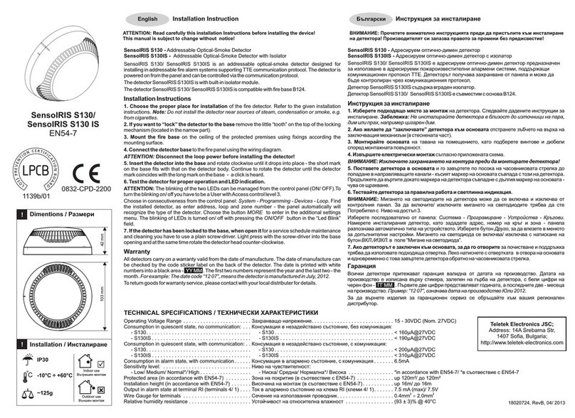
Teletek electronics SensoIRIS S130 Installation instruction
FireAngel
FireAngel P-LINE HT-630 User manual & installation guide
