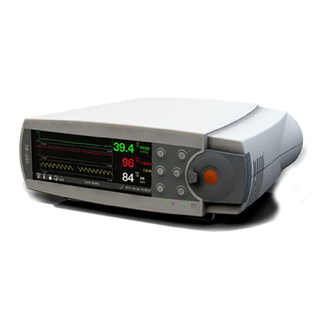
Sentec SDM User manual

Sentec Digital
Monitoring System
Installation at Home User Site by
Instructed Personnel

Sentec AG, Ringstrasse 39, CH-4106 Therwil, Switzerland, www.sentec.com
HB-010103-e Date of release: 01/2022
2
Required & recommended components for setup
REF: SDM
Sentec Digital Monitor
Class I ME equipment
IPX1
Transport/Storage
Operation
REF: RFT100VA-V1 / RFT100VA-V2
Sentec Isolation Transformer
(see chapter 3.2 for technical data)
IP42
Transport/Storage
Water Protection Box (not included)
IP44
Note: Recommended - a similar product with a minimum
degree of IPX2 (ingress protection) may be used.
SDM Mains Cable (enclosed with SDM)
Caution:Use only hospital-grade power cords provided by
Sentec.
Note: Mains cables are country specific, and may differ in
shape and/or color.
This manual provides systematic guidance for an instructed person from a homecare provider on setting up the
SDMS at the patient’s home/site. The SDMS shall only be used if all of the following steps have been carried out
successfully.
Note: Installation of the SDMS including configuration of the monitor (SDM) shall only be
performed by an instructed person from a homecare provider. This instructed person must
have received the appropriate training by a Sentec AG representative. SDMS-related tutorials
are available for online viewing at http://www.sentec.com/tv .
50 °C/122 °F
0 °C/32 °F
40 °C/104 °F
10 °C/41 °F
-10°C/14 °F
50 °C/122 °F
80 kPa
(<2000m a.s.l)

Sentec AG, Ringstrasse 39, CH-4106 Therwil, Switzerland, www.sentec.com
HB-010103-e Date of release: 01/2022
3
The instructed person from the homecare provider is responsible
-Before starting the installation at home environments, to disable the menu access of the monitor in
order to avoid patients changing monitor settings accidently or on purpose. (see section 1)
-To affix the enclosed label (EV-010188, depicted below) to the monitor.
-For setting up the monitor at the patient’s home/site and installation of the Isolation Transformer (see
section 2.3)
-For selecting appropriate measurement site(s), instructing the patient how to use Sentec Digital
Monitoring System (SDMS) and providing the “Directions for Lay Users”, HB-010069, to the patient.
Other relevant manuals to the SDMS are also available on www.sentec.com/ifu.
-To instruct the lay operator regarding the following:
•In the event of unforeseen incidents, error messages or unexplained changes in the
performance of the device, patients shall contact their home care provider’s instructed person.
•To use the SDM and the Isolation Transformer only in-house and under the specified
environmental conditions.
•To carefully route and fix cables to reduce the possibility of entanglement or strangulation.
•To make no changes to the device setup.
-For switching off and uninstalling the SDMS and disconnecting the Isolation Transformer (see section
2.4).
-For ensuring maintenance (see section 3).
Note: The patient as lay operator cannot modify the SDM’s configuration by using the SDM’s menu.
If the SDMS has been stored below 10 °C / 50 °F, it must be acclimatized for two hours at room
temperature before it can be connected to the mains or switched on. The SDMS may not be
installed and operated in moist rooms (e.g. bathroom).
The Sentec Digital Monitoring System (SDMS) is to be operated by instructed personnel only.
Carefully read this manual, the Technical Manual for the SDM (HB-005752), accessory
Directions for Use, all precautionary information, and specifications before operating the device
(available on www.sentec.com/ifu)
As an additional means of protection, Sentec recommends to connect equipment to a supply
main with protective earth and to ensure that power and protective ground lines are connected
correctly (see socket and wiring testing in the Annex).
During operation, the monitor must be connected to the AC power via the Isolation Transformer.
Use only accessories and spare parts supplied or recommended by Sentec AG. Do not perform
other service and repair activities than specified and described by Sentec AG. Failure to comply
may result in physical injury, inaccurate measurements, and/or damage to the device.

Sentec AG, Ringstrasse 39, CH-4106 Therwil, Switzerland, www.sentec.com
HB-010103-e Date of release: 01/2022
4
Electromagnetic interferences
Electrostatic discharge and transient bursts from mains may temporarily interfere with the
measurement. This can lead to wrong measurements.
Equipment emits electromagnetic fields. This can, for example, disturb other medical devices
or Radio Services.
The SDM should not be used adjacent to or stacked with other equipment as these can cause
electromagnetic interference and thereby result in incorrect measurements. If adjacent or
stacked use is necessary, the SDM should be observed to verify normal operation in the
configuration it is to be used.
Interference from interventional devices
The SDM is protected against electrostatic/ defibrillator discharge. Parameter display may be
temporarily affected during electrostatic discharge/defibrillation, but will rapidly recover.
Nevertheless, during electro-surgery the SDM, sensor and cables are to be physically separated
from the electro-surgical equipment. The sensor must not be placed between cutting and
counter electrode.
Radio equipment
Portable RF communications equipment (including peripherals such as antenna cables and
external antennas) should be used no closer than 30 cm (12 inches) to any part of the SDM,
including cables specified by the manufacturer. Wireless mobile devices must be held away
from the SDMS by at least 1 m (39.4 inches). Otherwise, degradation of the performance of this
equipment and at worst, incorrect measurements could result.

Sentec AG, Ringstrasse 39, CH-4106 Therwil, Switzerland, www.sentec.com
HB-010103-e Date of release: 01/2022
5
1. Configuring the SDM
The menu access of the monitor must be disabled in V-STATS™ to avoid patients changing monitor
settings accidently or on purpose.
Either select the preconfigured SDM Home Profile of V-STATS™ or follow the below steps:
1
Switch off auditory alarm signals permanently using V-STATS™.
2
Set the patient´s individual measurement parameters.
3
Then, select ‘System Settings/Display in Sleep Mode’.
4
Disable patient menu access by unticking the Menu Access box within the V-STATS™ system settings
For further information, refer to the V-STATS™ Instruction Manual
HB-006042.

Sentec AG, Ringstrasse 39, CH-4106 Therwil, Switzerland, www.sentec.com
HB-010103-e Date of release: 01/2022
6
2. Instructions for connecting the Isolation Transformer
(REF: RFT100VA-V1 and RFT100VA-V2)
2.1 Classification
The monitor SDM is a Class I ME equipment and IPX1 according to IEC 60601-1. The Isolation Transformer is an
additional MOPP according to IEC 60601-1-11.
2.2 Technical data Isolation Transformer
Type of single-phase transformer:
RFT100VA-V1
RFT100VA-V2
Primary Voltage:
100 – 120 V
230 V ±10%
Primary Current:
104 – 0.90 A
0.47 A
Secondary: Voltage:
100 – 120 V
230 V ± 10%
Secondary Current:
0.98 – 0.84 A
0.44 A
Frequency
50 – 60 Hz
50 – 60 Hz
Output:
100 VA
100 VA
Energy efficiency:
~ 94 %
~ 94 %
Earth leak current
<100 μA (127V)
<100 μA (254V)
Overheating Protection
120 °C / 248 °F
120 °C / 248 °F
Isolation class
ta 40/B
ta 40/B
Protection class plugs
IP 20
IP 20
Protection class transformer
IP 42
IP 42
Dimensions (LxWxH) ca.
160 x 126 x 73 mm
160 x 126 x 73 mm
Storage temperature
-10 °C to +50 °C /
14 °F to 122
°F
-10 °C to +50 °C /
14 °F to 122
°F
Operating Temperature
5 °C to +40 °C /
41 °F to 104 °F
5 °C to +40 °C /
41 °F to 104 °F
Weight
3.1 kg
3.1 kg
Expected lifetime: Under normal wear and tear, the expected lifetime for the Isolation Transformer is 7 years,
provided the recommended procedures are carried out and the device is not subject to misuse, neglect or
accident.
Operating positioning in normal use: horizontally, on the floor.

Sentec AG, Ringstrasse 39, CH-4106 Therwil, Switzerland, www.sentec.com
HB-010103-e Date of release: 01/2022
7
2.3 Connecting the Isolation Transformer
Important notes:
•The Isolation Transformer (RFT100VA-V1 and RFT100VA-V2) is intended for use only with the
Sentec Digital Monitor (SDM). Any modification to the Isolation Transformer, to the SDM or to the
installation procedure as described in this manual, may result in physical injury, inaccurate
measurements, and/or damage to the device.
•Do not use the Isolation Transformer if the housing or cables are damaged.
•Do not throw or drop the Isolation Transformer. This may damage the inside of the unit.
•Never connect the SDM mains cable to multiple socket outlets or extension cords.
The Isolation Transformer is only to be used below 2000 m a.s.l. (<80 kPa).
1
Place Isolation Transformer horizontally on the
floor.
Make sure the SDM mains cable is disconnected
from mains and from the SDM.
Connect the SDM mains cable (C13) to the isolation
transformer (C14).
2
Use the Water Protection Box (or similar product)
to secure the cable connection and place it on a flat
surface on the floor.
Note: Do not immerse Water Protection Box in
water.
3
Connect the transformer (C13 plug) to the SDM
(C14 socket).
C14
C13

Sentec AG, Ringstrasse 39, CH-4106 Therwil, Switzerland, www.sentec.com
HB-010103-e Date of release: 01/2022
8
4
Country specific example (CEE 7/7)
Plug the SDM mains cable into the wall socket. Do
not use extension cables or multipliers.
Ensure that the mains connection can be easily
disconnected from the mains supply.
Note: As an additional means of protection,
Sentec recommends to perform a socket and
wiring test prior to use (see Annex).
5
Circuit
Breakers
In case the circuit breakers on the back of the
Isolation Transformer are triggered, they can be
reset by pushing them back into their lock position.
Note: The Isolation Transformer has an overheat
protection inside, which responds at approx. 120°C
and switches off the transformer. The overheat
protection is self-resetting and will only switch on
the transformer again when it has cooled down.
Simplified depiction of final SDM & Isolation Transformer assembly
Instructed personnel from the homecare provider shall electrically test the Isolation Transformer at
least every 6 months (chapter 3.1).
Refer to the Instruction Manual for the SDMS (HB-005771) or Technical Manual for the SDMS (HB-005752)
for additional information, e.g. transport and storage conditions.
Troubleshooting is provided in the ‘Service Manual for the SDMS’ (HB-005615)
available on www.sentec.com/ifu.
Leave this Instruction Manual (HB-010103) at the patient’s home during monitoring
(also available on www.sentec.com/ifu).
Provide the Lay User Manual (HB-010069-Directions for Lay Users) to the patient (also available on
www.sentec.com/ifu).

Sentec AG, Ringstrasse 39, CH-4106 Therwil, Switzerland, www.sentec.com
HB-010103-e Date of release: 01/2022
9
2.4 Disconnecting the Isolation Transformer from SDM
1
Disconnect mains supply plug from the wall socket.
2
Open the Water Protection Box, remove and
disconnect the cables (C13, C14).
3
Disconnect the isolation transformer from the SDM.

Sentec AG, Ringstrasse 39, CH-4106 Therwil, Switzerland, www.sentec.com
HB-010103-e Date of release: 01/2022
10
3. Maintenance
Note: Instructed personnel/homecare providers must not repair the Isolation Transformer. If the Isolation
Transformer is defective, please contact qualified service personnel or your local Sentec representative.
Expected Useful Life1of electrical devices:
Product Name
REF
Expected Useful Life1
Sentec Digital Monitor SDM 7 years
Digital Sensor Adapter Cable
AC-150
AC-250
AC-750
7 years
Isolation Transformer RFT100VA-V1
RFT100VA-V2 7 years
V-Sign™ Sensor 2 VS-A/P/N up to 36 months
OxiVenT™ Sensor OV-A/P/N 12 months
1 The average amount of time that an item is estimated to function when installed new, assuming correct / diligent handling and routine
maintenance is practiced. For the avoidance of doubt, the indicated expected useful lifetime is for information purposes only and as such
does not constitute, imply or establish any warranty or guarantee.
Shelf Life of accessories and disposables (expiration date is stated on the packaging of the device):
Product Name
REF
Shelf Life ex. Sentec AG
Ear Clip EC-MI 12 months
Multi-Site Attachment Ring (Easy)
for mature/intact skin
MAR-MI
MARe-MI 12 months
Multi-Site Attachment Ring (Easy)
for sensitive/fragile skin
MAR-SF
MARe-SF 9 months
Service Gas GAS-0812 12 months
Contact Gel GEL-04
GEL-SD 12 month

Sentec AG, Ringstrasse 39, CH-4106 Therwil, Switzerland, www.sentec.com
HB-010103-e Date of release: 01/2022
11
3.1 Routine Checks
The Isolation Transformer shall be electrically tested at least every 6 months by the homecare provider’s
instructed personnel.
Visual Inspection:
The Isolation transformer shall be visually inspected (mandatory).
•Visual inspection according to IEC 62353
•Visual inspection of integrity of the cable isolation
•Visual inspection of integrity of circuit breakers
Electrical testing:
The Isolation transformer shall be tested according to IEC 62353 (mandatory); altered limits shall be
applied where mentioned below.
•Measuring of protective earth resistance with 25 A (recommended current for measurement).
Measure resistance between primary protective earth (C14 plug) and secondary protective
earth (C13 plug).
The resistance shall not exceed 100 mΩ.
•Measuring of the insulation resistance with 500V DC. Primary live & neutral shortened as well
as secondary live & neutral shortened.
Measure:
-primary vs. secondary
-primary vs. protective earth
-secondary vs. protective earth
The insulation resistance shall not be below 100 MΩ.
•Earth leakage currents:
Device under test must be in normal operating condition. The current shall be measured with
the mains polarity normal and reversed.
Measure current from secondary (live and neutral separately) to protective earth through the
leakage current measuring device.
The leakage currents shall not exceed 100 µA.
Functional Test
The Isolation transformer shall be tested according to IEC 62353 in combination with the Sentec
Digital Monitor (mandatory).
3.2 Cleaning/Disinfection
For cleaning and/or disinfecting the SDM, the TC Sensors and the Digital Sensor Adapter Cable, please refer to
www.sentec.com/ifu.
For cleaning the Isolation Transformer, use a dry or damp cloth. For disinfection, use a 70% isopropanol
moistened wipe.
Note: Instructed personnel/home care providers must clean and if necessary, disinfect the SDM, the TC
Sensors, the Digital Adapter Cable and the Isolation Transformer between uses on different patients.

Sentec AG, Ringstrasse 39, CH-4106 Therwil, Switzerland, www.sentec.com
HB-010103-e Date of release: 01/2022
12
4. Annex: Instructions for socket and wiring testing
(recommended)
As an additional means of protection, Sentec recommends performing a socket and wiring test prior to SDMS
installation to verify proper socket installation. The socket testing procedure must only be carried out by a
homecare provider’s instructed person.
The SDMS (including the isolation transformer) shall be connected to the tested socket only.
1
Socket Visual Inspection
Check the socket for visual damages and make sure the socket is clean. Otherwise, the socket must
not be used. If in doubt, please contact a qualified electrician or your local Sentec representative.
2
Socket Wiring Test
Check the socket for verification of proper electrical wiring.
•Verify no wire is missing.
•Verify live / neutral are connected to L/N terminals (may be inverted).
•Verify protective earth is connected to the PE terminal (N/PE must not be inverted!)
-Voltage between protective earth and neutral shall not exceed 50V AC
-Voltage between protective earth and live shall be similar to mains voltage (e.g. 230V AC)
Note: A socket tester may be used. Simple (passive) testers acc. to below example are not able to
detect N/PE inverted. Make sure the tester is working properly before testing. Do not leave the
tester with the patient.
The socket must not be used if it does not meet above criteria. If in doubt, please contact a qualified
electrician or your local Sentec representative.

Sentec AG, Ringstrasse 39, CH-4106 Therwil, Switzerland, www.sentec.com
HB-010103-e Date of release: 01/2022
13
5. Example Socket Tester for Installation at Home Use Sites
A basic socket tester similar to below example may be used to verify proper socket installation and wiring.
The below example may be substituted by other products.
For further information, refer to the respective socket tester’s Instructions for Use.
Plug Type
Rated operating
voltage
Brand Name
Socket Tester
Manufacturer
F + E (CEE 7/7)
Compatible to
Schuko plug
230 V/AC 50Hz
Voltcraft VC40
Conrad Electronic International
GmbH & Co. KG
www.conrad.com

Sentec AG, Ringstrasse 39, CH-4106 Therwil, Switzerland, www.sentec.com
HB-010103-e Date of release: 01/2022
14
6. Glossary of Symbols
Symbol
Name
Description of Symbol
Warning
Warnings alert users about a situation that, if not avoided, could result in
hazards or other serious adverse consequences from the use of a medical
device.
Caution
Cautions alert users to exercise appropriate care for safe and effective use
of the product and the care necessary to avoid damage to the product
that may occur as a result of use or misuse.
Catalogue number Indicates the manufacturer’s catalogue number so that the medical
device can be identified.
Serial number Indicates the manufacturer’s serial number so that a specific medical
device can be identified.
Medical Device Indicates that the device is a medical device.
Date of manufacture Indicates the date when the medical device was manufactured.
Manufacturer Indicates the medical device manufacturer.
Refer to instruction
manual/ booklet Indicates that the instruction manual must be read
Consult instructions
for use Indicates the need for the user to consult the instructions for use.
IP XY
IP class of device
Degree of ingress protection:
X: Protection against solids
Y: Protection against liquids
CE mark
Indicates that the product complies with the requirements of the Medical
Device Directive 93/42/EEC June 1993 or Medical Device Regulation
MDR EU 2017/745.
If applicable, the 4-digit Notified Body number is added near or below the
CE symbol.
WEEE Disposal
European consumers are obliged by law to dispose Waste Electrical and
Electronic Equipment (WEEE) according to the WEEE Directive
2012/19/EU:
1. All electrical and electronic waste must be stored, collected, treated,
recycled and disposed of separately from other waste.
2. Consumers are obliged by law to return electrical and electronic
devices at the end of their service lives to the public collection points set
up for this purpose or point of sale. Details to this are defined by the
national law of the respective country.
Note:
By recycling materials or other forms of utilizing old devices, you are
making an important contribution to protecting our environment.

Sentec AG, Ringstrasse 39, CH-4106 Therwil, Switzerland, www.sentec.com
HB-010103-e Date of release: 01/2022
15
Symbol
Name
Description of Symbol
Transformer Indicates that the product is a non-short-circuit proof isolating
transformer
Circuit Breakers Circuit breakers for transformer protection on the primary side against
overloads and short-circuits.
Defibrillation Proof
Type BF
Degree of protection against electrical shock: Defibrillation-proof, Type
BF applied part
Temperature limit Indicates the temperature limits to which the medical device can be
safely exposed
Fragile, handle with
care
Indicates a medical device that can be broken or damaged if not handled
carefully.
Keep dry Indicates a medical device that needs to be protected from moisture.
Atmospheric pressure
limitation
Indicates the atmospheric pressure limits to which the medical device can
be safely exposed.

Sentec AG, Ringstrasse 39, CH-4106 Therwil, Switzerland, www.sentec.com
HB-010103-e Date of release: 01/2022
16
Other manuals for SDM
2
Table of contents
Other Sentec Measuring Instrument manuals
Popular Measuring Instrument manuals by other brands

GESTRA
GESTRA LRG 16-40 Original Installation Instructions
Bante Instruments
Bante Instruments TB200 instruction manual
Trumpf
Trumpf Access Laser AL30 Series Operation manual
Vitrek
Vitrek 951i operating & maintenance manual
GW Instek
GW Instek GOM-802 user manual
Badger Meter
Badger Meter FC-5000 user manual
