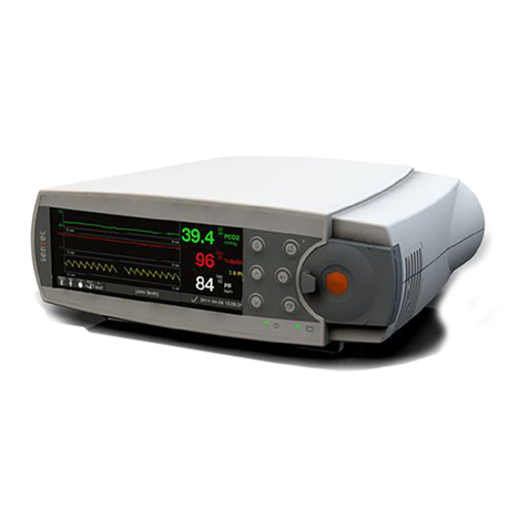
Sentec SDM User manual

For the SenTec Digital Monitoring System
(Software Version SMB V08.02; MPB V06.02)

HB-005615-j Service Manual
Warranty
The manufacturer warrants to the initial purchaser that each new SenTec Digital
Monitor will be free from defects in workmanship and materials. The manufacturer’s
sole obligation under this warranty is to at its own choice repair or replace any monitor
–for which the manufacturer acknowledges the warranty cover –with a replacement
monitor.
Warranty Exclusions and System Performance
SenTec AG can neither guarantee or verify instrument performance characteristics nor
accept warranty claims or product liability claims if the recommended procedures are
not carried out, if the product has been subject to misuse, neglect or accident, if the
product has been damaged by extraneous causes, if accessories other than those
recommended by SenTec AG are used, if the warranty seal on the lower side of the
monitor is broken, or if instrument repairs are not carried out by SenTec authorized
service personnel.
CAUTION: Federal law (U.S.) restricts this device to sale by or on the order of a physician.
Patents/Trademarks/Copyright
International Industrial Design No. DM/054179, Japanese Design No. 1137696, U.S.
Design Patent No. D483488.
Canadian Patent No. 2466105, European Patent No. 1335666, German Patent No.
50111822.5-08, Spanish Patent No. 2278818, Hongkong Patent No. HK1059553, U.S.
Patent No. 6760610.
Chinese Patent No. ZL02829715.6, European Patent No. 1535055, German Patent No.
50213115.2, Spanish Patent No. 2316584, Indian Patent No. 201300, Japanese Patent
No. 4344691, U.S. Patent No. 7862698.
SenTec™, V-Sign™, V-STATS™, V-CareNeT™, V-Check™, Staysite™, OxiVenT™,
Advancing Noninvasive Patient Monitoring™, and Illuminate Ventilation™ are
trademarks of SenTec AG / © 2019 SenTec AG. All rights reserved. The contents of
this document may not be reproduced in any form or communicated to any third party
without the prior written consent of SenTec AG. While every effort is made to ensure
the correctness of the information provided in this document, SenTec AG assumes no
responsibility for errors or omissions. This document is subject to change without
notice.
SenTec AG, Ringstrasse 39, 4106 Therwil, Switzerland, www.sentec.com
Patient Monitor
IN ACCORDANCE WITH IEC 60601-1; ANSI/AAMI ES60601-1; CAN/CSA C22.2 No.
60601-1, IEC 60601-1-2, IEC 60601-2-23, ISO 80601-2-61.

Contents
SenTec Digital Monitoring System i
Contents
Contents i
Figures ii
Tables ii
Abbreviations ii
1INTRODUCTION 1
1.1 Related Documents 2
1.2 Safety Information 4
2THE SENTEC DIGITAL MONITORING SYSTEM (SDMS) 11
2.1 Components 11
2.2 The SenTec Digital Monitor (SDM) 12
3MAINTENANCE/SAFETY & FUNCTIONALITY TESTS 14
3.1 SenTec TC Sensors 15
3.2 SenTec Digital Monitor 30
3.3 Docking Station 41
3.4 Digital Sensor Adapter Cable 42
3.5 Opening the Membrane Changer 43
4TROUBLESHOOTING 44
4.1 How to use the troubleshooting list 44
4.2 Troubleshooting List 46
5REPAIRS OF THE SDM 73
5.1 Prior to Repair 74
5.2 Replacement, Tip-up Foot 74
5.3 Replacement, Silicon Foot 75
5.4 Replacement, main fuses 75
5.5 Replacement, Docking Station Door 76
5.6 Replacement, Docking Station Gasket 77
6SOFTWARE UPDATES 79
7DISPOSAL 80
7.1 SenTec Digital Monitor 80
7.2 Cables 80
7.3 SenTec TC Sensors 80
7.4 Service Gas Bottle 80
7.5 Consumables 80
8APPENDIX 81
8.1 Protocol for Safety & Functionality Test 81
8.2 Testing Accessories and Spare Parts 81
8.3 Repair or Investigation Request Form 81
8.4 Repair Reporting Form 81
8.5 Customer Feedback Form 81
8.6 Instructions for Shipment 81
8.7 Certificate for Disinfection 81
8.8 SDMS Maintenance Checklist 82
8.9 Interfaces - Pin Assignement 82
8.10 Technical Specifications 86
8.11 Contact 86

HB-005615-j
ii
Figures
Figure 1 Front Panel of the SDM 12
Figure 2 Rear Panel of the SDM 13
Figure 3 Removal of the Membrane from the TC Sensor 16
Figure 4 Top view of the V-Sign™ Sensor 17
Figure 5 Inspection after remembraning the sensor 18
Figure 6 Examples: PCO2 and PO2 Slope Test 22
Figure 7 Connections for the High Potential Test, AP 31
Figure 8 Connections for the High Potential Test, PC 32
Figure 9 Connections for the Safety Test 34
Figure 10 Correct orientation of the Docking Station Gasket 41
Figure 11 Opening the Membrane Changer 43
Figure 12 Replacement, Tip-up Foot 74
Figure 13 Replacement, Silicon Foot 75
Figure 14 Replacement, Main Fuses 75
Figure 15 Docking Station Door Insertion 76
Figure 16 Replacement, Docking Station Gasket 77
Figure 17 Positioning of the Docking Station Gasket 78
Figure 18 Sensor Connection Port 83
Figure 19 Serial Data Port (RS-232) 84
Figure 20 Multipurpose I/O Port 84
Tables
Table 1 Related Documents 2
Table 2 Components of the SDMS 11
Table 3 Connections for the High Potential Test, AP 31
Table 4 Connections for the High Potential Test, PC 32
Table 5 Example of a Troubleshooting Procedure 45
Table 6 Troubleshooting PCO2/ PO2 Monitoring 47
Table 7 Troubleshooting SpO2/ PR Monitoring 53
Table 8 Sensor specific troubleshooting 54
Table 9 SDM specific troubleshooting 59
Table 10 Docking Station specific troubleshooting 69
Table 11 Pin Assignment, Sensor Connection Port 83
Table 12 Pin Assignment, Serial Data Port (RS-232) 84
Table 13 Pin Assignment, Multipurpose I/O Port 85
Abbreviations
AHP Absolute Heating Power
CO2 Carbon dioxide
DS Docking Station (calibration unit being integrated in the SDM)
HP Heating Power
HPM Heating Power Mode
LED Light emitting diode
MRI Magnetic Resonance Imaging
O2 Oxygen
PaCO2 Arterial carbon dioxide partial pressure
PaO2 Arterial oxygen partial pressure
PcCO2 Cutaneous carbon dioxide partial pressure (i.e. the CO2 partial pressure at the skin
surface)
PCO2 Used to display/label tcPCO2 on the SDM and –unless explicitely stated otherwise –
throughout this manual
PcO2 Cutaneous oxygen partial pressure (i.e. the O2 partial pressure at the skin surface)

SenTec Digital Monitoring System iii
PI Pulsation Index
PO2 Used to display/label tcPO2 on the SDM and –unless explicitely stated otherwise -
throughout this manual
POST Power-On Self-Test
RO Responsible Organization
PR Pulse rate
RHP Relative Heating Power
RMI Remote monitoring interrupted
SaO2 Arterial oxygen saturation
SDM SenTec Digital Monitor
SDMS SenTec Digital Monitoring System
SpO2 Functional oxygen saturation of arterial hemoglobin as measured with a pulse
oximeter
TC Transcutaneous
tcPCO2 Transcutaneous carbon dioxide partial pressure, i.e. an estimate of PaCO2 calculated
from the measured PcCO2 and displayed/labeled on the SDM and - unless explicitly
stated otherwise - throughout this manual as ‘PCO2’
tcPO2 Transcutaneous oxygen partial pressure, i.e. an estimate of PaO2 calculated from the
measured PcO2 and displayed/labeled on the SDM and - unless explicitly stated
otherwise - throughout this manual as ‘PO2’
VOM V-CareNeT™ Only Mode


1 Introduction
SenTec Digital Monitoring System
1
1Introduction
This Manual provides information on
maintenance and safety and functionality tests for the SenTec Digital
Monitoring System (SDMS) intended for qualified personnel only (
see
section 3
);
troubleshooting for the SDMS (
see section 4
). The troubleshooting list covers
three levels of recommended troubleshooting procedures a) for the operator,
b) for qualified personnel, and c) for SenTec authorized technicians only;
repair procedures that do not require opening the cover of the SDM intended
for qualified personnel only (
see section 5
).
Note:
Repairs that require opening the SDM cover are described within SenTec`s
Repair Manual for the SDMS
(which is distributed to SenTec authorized
service personnel only). Within this manual, activities described as “for
SenTec authorized service technicians only” refer to activities described in
detail within the
Repair Manual for the SDMS
(HB-005755).
This manual must be read carefully prior performing service or repairs.
Section
1.2, "Safety Information"
must be read and understood.
This Manual contains confidential information. The contents of this
document may not be reproduced in any form or communicated to any third
party without the prior written consent of SenTec AG.

1 Introduction
HB-005615-j
2
1.1 Related Documents
To perform service or repairs you must know how to operate the SDMS. The SDMS
consists of the SenTec Digital Monitor (SDM), sensors and accessories.
Refer to the following Manuals and Directions for Use:
Table 1 Related Documents
System
component
Manual
Content
SDMS
Manual CD
With the exception of the
Repair Manual for the SDMS
all documents listed in this Table are available on the
Manual CD.
SDMS
Quick Reference Guide
for the SDMS
Routine Use: The Q
uick Reference Guide for the SDMS
summarizes the key essentials on just 2 pages.
SDMS
Instruction Manual for
the SDMS
Getting started / Using the SDMS: The
Instruction
Manual for the SDM
S highlights the essential points
when using the SDMS. To ensure proper operation of
the SDMS, precisely follow the instructions provided in
the
Instruction Manual for the SDMS
step by step.
Contains routine checks and maintenance procedures
that can be performed by the operator.
SDM
Technical Manual for the
SDM
HB-005752
The
Technical Manual for the SDM
provides detailed
information on the SenTec Digital Monitor (SDM).
SDMS
Service Manual for the
SDMS (present manual)
Provides information on maintenance, safety and
functionality tests, troubleshooting and repair
procedures that do not require opening the cover
of the SDM as well as on service/maintenance
procedures for sensors.
SDMS
Repair Manual for the
SDMS
HB-005755
The
Repair Manual for the SDMS
covers repair
procedures on the opened SDM. The
Repair Manual
for the SDMS
is distributed to SenTec authorized
service personnel only.
Sensors /
Disposables
Respective Directions for
Use
Additional information on SenTec TC Sensors, the
Membrane Changer and Membrane Changer Insert, the
Ear Clip, the Multi-Site Attachment Rings, and SenTec’s
Staysite™ Adhesive is provided in the respective
Directions for Use.
V-STATS™
Installation Manual for
V-STATS™
This manual describes the procedures to install
V-STATS™ on a PC.
V-STATS™
Instruction Manual for
V-STATS™
The Instruction Manual for V-STATS™ provides detailed
information on V-STATS™.

1 Introduction
SenTec Digital Monitoring System
3
Note:
Related forms (as referenced within this manual) are listed in
section 8
“Appendix”.
Note:
The
Quick Reference Guide for the SDMS
and the
Instruction Manual for the
SDMS
in all available languages can also be downloaded from SenTec’s
Webpage (https://www.sentec.com/education/customer-portal).
Information / Instructions about the Digital Sensor Adapter Cable, the
Contact Gel and the Service Gas are provided in the
Instruction Manual for
the SDMS
and the
Technical Manual for the SDM
.
Note:
SDMS related tutorials are available for online viewing
at http://www.sentec.com/tv

1 Introduction
HB-005615-j
4
1.2 Safety Information
Warnings
This symbol identifies a WARNING statement. Warnings alert
users to potential serious outcomes (death, injury, or adverse
events) to the patient, user, or environment.
Cautions
This symbol identifies a CAUTION statement. Cautions alert
users to exercise appropriate care for safe and effective use of
the product and the care necessary to avoid damage to the
product that may occur as a result of use or misuse.
Carefully read all safety information in this Manual and in the
Technical Manual for the
SDM (HB-005752)
before operating the device or performing service/repairs.

1 Introduction
SenTec Digital Monitoring System
5
1.2.1 General Safety Information
WARNING: The SenTec Digital Monitoring System (SDMS) is to
be operated by qualified personnel only. Read this manual,
accessory Directions for Use, all precautionary information, and
specifications before use.
WARNING: The SenTec Digital Monitor (SDM) is not intended
for diagnosis, it is intended only as an adjunct in patient
assessment. It must be used in conjunction with clinical signs
and symptoms. The SDM is a cutaneous blood gas monitor and
not a blood gas analyzer.
WARNING: Do not use SDMs, sensors, cables, or connectors
that appear damaged.
WARNING: Carefully route and fix cables to reduce the
possibility of patient entanglement or strangulation.
WARNING: To ensure patient safety, do not place the SDM in
any position that might cause it to fall on the patient.
WARNING: Do not lift the SDM by the sensor cable or the AC
power cord because they could disconnect from the SDM,
causing the SDM to fall on the patient.
WARNING: Do not spray, pour, or spill any liquid on the SDM,
its accessories, connectors, switches, or openings in the chassis.
If the SDM has been wetted accidentally, it must be removed
from AC power, wiped dry externally, allowed to dry thoroughly,
and inspected by qualified service personnel before further use.
WARNING: Keep the SDM (as well as any discarded parts) out
of reach of children under the age of 5 years. Some parts of the
SDM are small enough to be swallowed and may block the
trachea.
WARNING: Explosion and flammability hazards. Do not use the
SDM in the presence of flammable anesthetics / gases or other
flammable substances in any environment which has increased
oxygen content.

1 Introduction
HB-005615-j
6
WARNING: The SDMS only can be used in patients undergoing
hyperbaric therapy if the SDM (monitor) remains outside the
hyperbaric environment.
WARNING: The SDM is protected against electrostatic/
defibrillator discharge. Parameter display may be temporarily
affected during discharge/ defibrillation, but will rapidly recover.
Precisely follow the instructions given in the defibrillator manual.
WARNING: This device has been tested and found to comply
with the requirements for medical devices according to the IEC
60601-1-2, and the Medical Device Directive 93/42/EEC. These
requirements are designed to provide reasonable protection
against harmful interference in a typical medical installation.
WARNING: To ensure protection of patient, operator and
equipment from the effects of defibrillation and diathermy/
electro-surgery, cables manufactured by SenTec AG must be
used.
WARNING: During normal operation (except transport), it is
recommended that the monitor is always connected to the AC
power outlet.
WARNING: Do not connect the SDM to an electrical outlet
controlled by a wall switch, because the SDM may be accidentally
turned off once the battery is depleted.
WARNING: To avoid risk of electric shock, this equipment
should be connected to a supply mains with protective earth.
Ensure that power and protective ground lines are connected
correctly. If case of doubt (e.g. as this may be the case during
home use of the SDM) disconnect the SDM from the outlet and
use the battery power during patient monitoring.
WARNING: Do not use the protective earth terminal for any
other purpose than protective earthing or functional earthing.
WARNING: For US, respectively Japan: Grounding reliability
can only be achieved when the SDM is connected to an
equivalent receptacle marked HG (Hospital Grade), respectively
HGJ (Hospital Grade Japan).

1 Introduction
SenTec Digital Monitoring System
7
WARNING: The SDM should not be used adjacent to or stacked
with other equipment as these can cause electromagnetic
interference and thereby result in incorrect measurements. If
adjacent or stacked use is necessary, the SDM should be
observed to verify normal operation in the configuration it is to
be used.
WARNING: Certain types of mobile telecommunication
equipment could potentially interfere with SDM operation. Mobile
telecommunication equipment should not be used within five
meters (16.4 feet) of the SDM. Otherwise, degradation of the
device performance could result.
WARNING: The use of accessories, sensors, and cables other
than those specified may result in increased emission and/or
decreased immunity and inaccurate readings of the SDM.
WARNING: When connecting/ mounting the SDM to accessory
equipment (e.g. PCs, PSG-Systems, (wireless) networks, roll
stands, mounting plates, incubators, etc.)), verify proper
operation before clinical use of the SDM and accessory
equipment. In certain cases it may be required that the SDM and
the accessory equipment must be connected to a grounded AC
outlet. In case of doubt consult qualified technicians.
WARNING: Accessory equipment (e.g. a PC) connected to the
SDM’s data ports must be certified according to the IEC 60950
standard. All resulting combinations of equipment must be in
compliance with the IEC standard 60601-1 systems
requirements. Anyone who connects accessory equipment to the
SDM configures a medical system and is, therefore, responsible
for ensuring that the resulting system complies with the
requirements of standard IEC 60601-1 and the electromagnetic
compatibility standard IEC 60601-1-2.
WARNING: The mains power supply of the SenTec Digital
Monitor (SDM) is separated by two Means of Patient Protection
(MOPPs) between the sensor port (for the applied part, the
sensor) and the interface connectors. The three interface
connectors - serial data port, Multipurpose I/O port (analog
outputs, nurse call), LAN port - of the SDM are not separated
from each other. If at a time accessory equipment is connected
to only one of the three interface connectors no additional safety
measures are necessary to comply with the requirements of IEC
60601-1. If however accessory equipment is simultaneously
connected to two or three of the SDM’s interface connectors

1 Introduction
HB-005615-j
8
additional safety measures may be required to be compliant with
the requirements of IEC 60601-1. In case of doubt consult
qualified technicians.
WARNING: The Roll Stand, model RS_SDM, is intended for use
with the SDM only or in combination with the Cable Cleat, model
CC_SDM, and the SDM. The mounting plates are intended for
use with the SenTec Digital Monitor (SDM) only. Do not use the
accessories for devices from other manufacturers than SenTec
together with SenTec Digital Monitoring System (SDMS).
WARNING: Do not attach the basket of the Roll Stand, model
RS_SDM, in any position that might cause it to tip over and
possibly fall on the patient. Ensure that the Roll Stand does not
tip over with and without the SDM being mounted to it.
WARNING: This warning applies to all SDMs with serial
numbers less than or equal to 302968 provided that the open
thread has not been replaced by a blind thread already or is not
sealed with slotted setscrew and thread locking adhesive. A
screw entering 17 mm (0.67 inches) into one of the SDM’s screw
holes may touch the primary part of the SDM’s power supply. If
this screw is electrically conducting the resulting short circuit
may cause an electrical isolation failure and, consequently, if the
SDM is connected to AC power an electrical shock may occur to
a person touching this screw or any other electrically conducting
material being in contact with this screw.
CAUTION: To maintain monitor readiness in-between
monitoring if using a SenTec TC Sensor:
1. ALWAYS clean the sensor before putting it into the
Docking Station!
2. ALWAYS store the clean sensor in the Docking Station!
3. ALWAYS keep the monitor switched on!
CAUTION: Do not immerse the SDM nor the connectors of any
connecting cables in liquid solution. Plugs and connectors
meticulously have to be kept clean and dry at all times.

1 Introduction
SenTec Digital Monitoring System
9
CAUTION: To ensure accurate performance and prevent device
failure, do not subject the SDM to heavy moisture, such as direct
exposure to rain. Such exposure may cause inaccurate
performance or device failure. If the SDM becomes wet
accidentally, it should be removed from AC power, wiped dry
externally, allowed to dry thoroughly, and inspected by qualified
service personnel before further use.
CAUTION: Do not sterilize any parts of the SDMS by irradiation,
steam, ethylene oxide, or H2O2 plasma.
CAUTION: Ensure that the SDM is properly grounded when
operating on AC power. If you are uncertain whether the AC
outlet is properly grounded, disconnect the SDM from the outlet
and use the battery power. Contact a qualified electrician to
examine the outlet for ground connections.
CAUTION: When installing/setting up the SDM, ensure that the
SDM can easily be disconnected from the AC power source at
any given time.
CAUTION: Use only hospital-grade power cords provided by
SenTec.
CAUTION: Ensure to always use the correct type and rating of
live and neutral fuses. Otherwise you risk damage or malfunction
of the SDM.
CAUTION: If the monitor is operated on an AC power source
with a depleted battery and the AC power is subsequently lost,
the monitor will shut down immediately.
CAUTION: Ensure that the fan of the SDM is clear of any
obstructions and that the SDM is located in a well-ventilated
dust-free atmosphere. Failure to do so could cause damage or
malfunction of the SDM.

1 Introduction
HB-005615-j
10
1.2.2 Safety Information regarding Repair and
Service Operations
WARNING: Maintenance and repair requiring removal of the
case or covers must be performed by SenTec authorized service
personnel.
WARNING: Before attempting to open or disassemble the SDM,
disconnect the device from the AC power outlet.
WARNING: Before replacing fuses of the SDM, disconnect the
device from the AC power outlet.
WARNING: Use only accessories and spare parts supplied or
recommended by SenTec AG. Do not perform other service and
repair activities than specified and described by SenTec AG.
Failure to comply may result in physical injury, inaccurate
measurements, and/or damage to the device.
WARNING: Chemicals from a broken LCD display panel are
toxic when ingested. Use caution when handling a SDM with a
broken display panel. Electronic components may content toxic
chemicals. Do not ingest chemicals from a broken electronic
component.
WARNING: Dispose of battery in accordance with local
requirements and regulations.
CAUTION: Follow ESD (Electrostatic discharge) precautions
when working with the SDM, especially when disassembling and
reassembling the SDM and when handling any of the
components. Use an ESD protective wrist-strap and table-mat
connected to Earth while working with the electronics.
CAUTION: When reassembling the SDM tighten the screws to
a torque of 5 Nm. Over-tightening could strip out the screw
holes, rendering the part unusable.

2 The SenTec Digital Monitoring System (SDMS)
SenTec Digital Monitoring System
11
2The SenTec Digital Monitoring
System (SDMS)
2.1 Components
The SenTec Digital Monitoring System (SDMS) comprises the following main
components:
Table 2 Components of the SDMS
REF
Product
SDM
SenTec Digital Monitor (including mains power cord)
SDMs with firmware version SMB SW-V08.00/ MPB SW-V06.00 are available
with/without factory preconfigured PO2-option.
VS-A/P/N
V-Sign™ Sensor 2 (for PCO2, SpO2/PR monitoring)
OV-A/P/N
OxiVenT™ Sensor (for PCO2, PO2, SpO2/PR monitoring)
AC-YYY
Digital Sensor Adapter Cable (to connect VS-A/P/N or OV-A/P/N to SDM; YYY=150,
250, 750 cm)
EC-MI
Ear Clip (to apply SenTec TC Sensors at earlobe of patients with mature/ intact skin)
MAR-MI
Multi-Site Attachment Ring MAR-MI (to apply SenTec TC Sensors to patients with
mature/ intact skin)
MAR-SF
Multi-Site Attachment Ring MAR-SF (to apply SenTec TC Sensors to patients with
sensitive/ fragile skin)
SA-MAR
Staysite™ Adhesive for the Multi-Site Attachment Rings (attaches complementary
the MAR-SF/MI to the skin with an additional adhesive film)
GEL-04
Contact Gel (contact liquid to apply SenTec TC Sensors to the patient)
MC-R
Membrane Changer (to change the membrane of SenTec TC Sensors)
MC-I
Membrane Changer Insert (separately bagged, single-use Inserts for the MC-R)
GAS-0812
Service Gas (needed to calibrate SenTec TC Sensors)
V-STATS_CD
V-STATS™ (PC based Trend Data Download/ Analysis, Remote Monitoring, and
Configuration Software for SenTec Digital Monitors)
Note:
The components listed above do not necessarily correspond to the scope of
delivery. Please refer to SenTec’s Webpage (www.Sentec.com/products) for
additional information and other available accessories.

2 The SenTec Digital Monitoring System (SDMS)
HB-005615-j
12
2.2 The SenTec Digital Monitor (SDM)
2.2.1 Front Panel
1Trend Display Area
2Numerical Display Area
3Menu/ Previous Level Button
4AUDIO PAUSED/OFF Button
5AUDIO PAUSED/OFF Indicator (yellow LED)
6Door Handle
7Docking Station Door
(colored dot in center of door indicates the
SDM’s PO2 activation status: blue if
activated, orange otherwise)
8Enter Button
9Display Button
10 AC Power/Battery Indicator
(green/yellow LED)
11 UP/DOWN Buttons
12 ON/OFF Indicator (green LED)
13 Status Bar
14 Speaker (on the side)
Figure 1 Front Panel of the SDM
Note:
SDMs with firmware version SMB SW-V08.00/ MPB SW-V06.00 are available
with and without activated PO2-option. If the PO2-option is activated the
colored dot in the Docking Station Door of the respective SDM will be blue,
otherwise orange.

2 The SenTec Digital Monitoring System (SDMS)
SenTec Digital Monitoring System
13
2.2.2 Rear Panel
15 Sensor Connection Port
16 Multipurpose I/O-Port
(Nurse call, analog output)
17 Serial Data Port (RS-232)
18 Network Port (LAN)
19 Gas Bottle Slot
20 Fan
21 Equipotential Terminal Connector
(ground)
22 Fuse Holder
23 AC Power Connector
24 ON/OFF Switch
Figure 2 Rear Panel of the SDM
WARNING: Refer to
section 1.2.1
for warnings related to
connecting/mounting the SDM to accessory equipment.
CAUTION: Ensure to always use the correct type and rating of
live and neutral fuses. Otherwise you risk damage or malfunction
of the SDM.
CAUTION: Ensure that the fan of the SDM is clear of any
obstructions and that the SDM is located in a well-ventilated
dust-free atmosphere. Failure to do so could cause damage or
malfunction of the SDM.

3 Maintenance/Safety & Functionality Tests
HB-005615-j
14
3Maintenance/Safety &
Functionality Tests
At normal use there is no internal adjustment or new calibration of the SDM required.
However, to guarantee continuous performance, reliability and safety of the SDMS
routine checks and maintenance procedures (including cleaning/disinfection) as well
as safety checks should be performed regularly.
Routine checks and maintenance procedures that can be performed by the operator
are provided in the
Instruction Manual for the SDMS
. Instructions for cleaning and/or
disinfecting the SenTec Digital Monitor (SDM) and the ‘Digital Sensor Adapter Cable’,
are provided in the
Technical Manual for the SDM
. Please refer to the respective
Directions for Use for instructions for cleaning and/or disinfection of SenTec TC
Sensors. For a better overview and documentation of periodic routine checks and
maintenance to be performed by the operator the SenTec form
HB-007601
“SDMS
Maintenance Checklist”
(
see section 8.7
) is available (refer to the Manual CD).
It is recommended that qualified service personnel performs the maintenance and
a complete safety and functionality test as specified in this Manual at regular intervals
(recommended every 12 month but at least every 24 months). Use the
HB-005638
“Protocol for Safety & Functionality Test”
(
see section 8.1 "Protocol for Safety &
Functionality Test")
to guide you through the complete "Safety & Functionality Test"
and to document your test results. To perform a complete "Safety &
Functionality Test" all tests described in this chapter MUST be performed.
Note: Prior to maintenance, service or repairs all components of the SDMS must be
cleaned and disinfected. If equipment is send to service personnel, a local
SenTec representative or to SenTec AG a completed
“Certificate for
Disinfection”
(
see section 8.7
) must be attached.
WARNING: If any of the tests specified below fails, the
respective problem must be fixed before the equipment is
returned to the user.
Other manuals for SDM
2
Table of contents
Other Sentec Measuring Instrument manuals
