SENTRONIC Mini-M Series User manual

MODEL: M2SES2
Super-mini Signal Conditioners Mini-M Series
HIGH/LOW SELECTOR
(with simple loop test output)
Functions & Features
• Monitors two DC input signals and transmitting an output
signal proportional to the higher or lower input
• Simple loop test output (0, 50, 100 %)
• High-density mounting
• CE marking
Typical Applications
• Selecting greater flow, pressure, etc. for control
• Heating control by multiple T/C’s on a furnace
Model
SPAN
ZERO
INP1
SPAN
ZERO
STAT2
STAT1
INP2
23 (.91)
76
(2.99)
mm (inch)
124
(4.88)
MODEL: M2SES2–[1][2]–[3][4]
ORDERING INFORMATION
• Code number: M2SES2-[1][2]-[3][4]
Specify a code from below for [1] and [4].
(e.g. M2SES2-AA-M2/CE/Q)
• Special output range (For codes Z & 0)
• Specify the specification for option code /Q
(e.g. /C01/S01)
[1] INPUT
Current
A: 4 – 20 mA DC (Input resistance 250 Ω)
B: 2 – 10 mA DC (Input resistance 500 Ω)
C: 1 – 5 mA DC (Input resistance 1000 Ω)
H: 10 – 50 mA DC (Input resistance 100 Ω)
Voltage
6: 1 – 5 V DC (Input resistance 1 MΩ min.)
[2] OUTPUT
Current
A: 4 – 20 mA DC (Load resistance 750 Ω max.)
B: 2 – 10 mA DC (Load resistance 1500 Ω max.)
C: 1 – 5 mA DC (Load resistance 3000 Ω max.)
D: 0 – 20 mA DC (Load resistance 750 Ω max.)
E: 0 – 16 mA DC (Load resistance 900 Ω max.)
F: 0 – 10 mA DC (Load resistance 1500 Ω max.)
G: 0 – 1 mA DC (Load resistance 15 kΩ max.)
Z: Specify current (See OUTPUT SPECIFICATIONS)
Voltage
1: 0 – 10 mV DC (Load resistance 10 kΩ min.)
2: 0 – 100 mV DC (Load resistance 100 kΩ min.)
3: 0 – 1 V DC (Load resistance 1000 Ω min.)
4: 0 – 10 V DC (Load resistance 10 kΩ min.)
5: 0 – 5 V DC (Load resistance 5000 Ω min.)
6: 1 – 5 V DC (Load resistance 5000 Ω min.)
4W: -10 – +10 V DC (Load resistance 10 kΩ min.)
5W: -5 – +5 V DC (Load resistance 5000 Ω min.)
0: Specify voltage (See OUTPUT SPECIFICATIONS)
[3] POWER INPUT
AC Power
M: 85 – 264 V AC (Operational voltage range 85 – 264 V,
47 – 66 Hz)
(Select ‘/N’ for ‘Standards & Approvals’ code.)
M2: 100 – 240 V AC (Operational voltage range 85 – 264 V,
47 – 66 Hz)
DC Power
R: 24 V DC
(Operational voltage range 24 V ±10 %, ripple 10 %p-p max.)
R2: 11 – 27 V DC
(Operational voltage range 11 – 27 V, ripple 10 %p-p max.)
(Select ‘/N’ for ‘Standards & Approvals’ code.)
P: 110 V DC
(Operational voltage range 85 – 150 V, ripple 10 %p-p max.)
[4] OPTIONS (multiple selections)
STANDARDS & APPROVALS (must be specified)
/N: Without CE or UL
/CE: CE marking
OTHER OPTIONS
blank: none
/Q: Option other than the above (specify the specification)
SPECIFICATIONS OF OPTION: Q (multiple selections)
COATING (For the detail, refer to M-System's web site.)
/C01: Silicone coating
/C02: Polyurethane coating
/C03: Rubber coating
TERMINAL SCREW MATERIAL
/S01: Stainless steel
GENERAL SPECIFICATIONS
Construction: Plug-in
Connection: M3 screw terminals (torque 0.8 N·m)
Rugghölzli 2
CH - 5453 Busslingen Tel.+41 (0)56 222 38 18
Fax +41 (0)56 222 10 12 mailbox@sentronic.com
www.sentronic.com
Produkte, Support und Service
SENTRONICAG

MODEL: M2SES2
Housing material: Flame-resistant resin (black)
Isolation: Input to output to power
Overrange output: Approx. -10 to +120 % at 1 – 5 V
Input zero adjustments: -2 to +2 % (front)
Input span adjustments: 98 to 102 % (front)
DIP switch setting: Selecting output options
Status indicator LED 1: Green LED; indicates the
transmitter’s function mode (Refer to the instruction
manual.)
Status indicator LED 2: Orange LED; indicates the
transmitter’s function mode (Refer to the instruction
manual.)
INPUT SPECIFICATIONS
• DC Current: Input resistor incorporated
OUTPUT SPECIFICATIONS
• DC Current: 0 – 20 mA DC
Minimum span: 1 mA
Offset: Max. 1.5 times span
Load resistance: Output drive 15 V max.
• DC Voltage: -10 – +12 V DC
Minimum span: 5 mV
Offset: Max. 1.5 times span
Load resistance: Output drive 1 mA max.; at ≥ 0.5 V
INSTALLATION
Power Consumption
•AC Power input:
Approx. 3 VA at 100 V
Approx. 4 VA at 200 V
Approx. 5 VA at 264 V
•DC Power input: Approx. 3 W
Operating temperature: -5 to +55°C (23 to 131°F)
Operating humidity: 30 to 90 %RH (non-condensing)
Mounting: Surface or DIN rail
Weight: 150 g (0.33 lbs)
PERFORMANCE in percentage of span
Accuracy: ±0.2 %
Temp. coefficient: ±0.015 %/°C (±0.008 %/°F)
Response time: ≤ 0.5 sec. (0 – 90 %)
Line voltage effect: ±0.1 % over voltage range
Insulation resistance: ≥ 100 MΩ with 500 V DC
Dielectric strength: 2000 V AC @1 minute (input to output
to power to ground)
STANDARDS & APPROVALS
CE conformity:
EMC Directive (2004/108/EC)
EN 61000-6-4 (EMI)
EN 61000-6-2 (EMS)
Low Voltage Directive (2006/95/EC)
EN 61010-1
Installation Category II
Pollution Degree 2
Max. operating voltage 300 V
Input or output to power: Reinforced insulation
Input to output: Basic insulation
Rugghölzli 2
CH - 5453 Busslingen Tel.+41 (0)56 222 38 18
Fax +41 (0)56 222 10 12 mailbox@sentronic.com
www.sentronic.com
Produkte, Support und Service
SENTRONICAG
MODEL: M2SES2
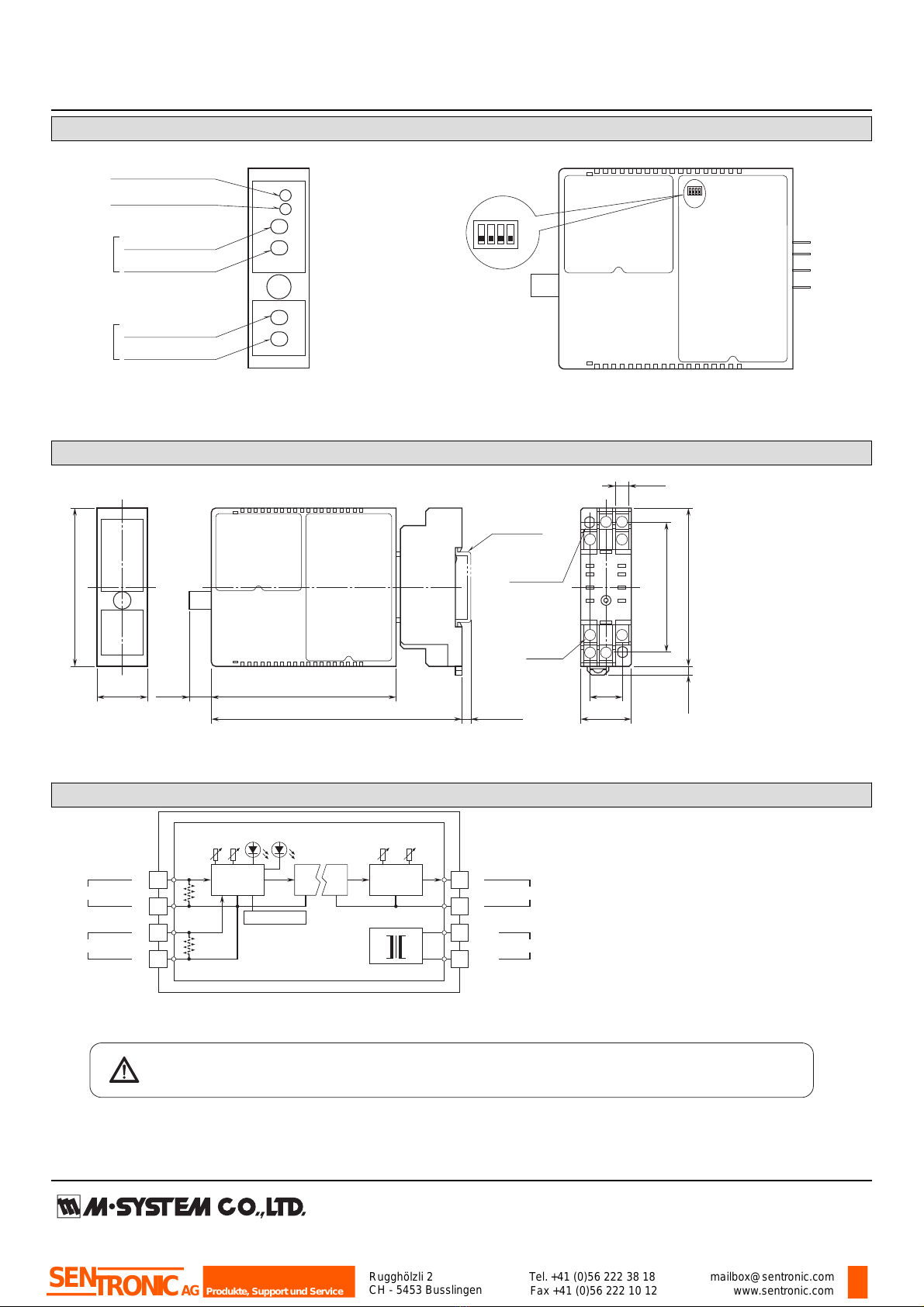
EXTERNAL VIEW
■FRONT VIEW ■SIDE VIEW
OFF
ON
1 2 3 4
SW1
Output Function
Setting
Zero Adj. (ZERO1)
Span Adj. (SPAN1)
Zero Adj. (ZERO2)
Status Indicator LED1
Status Indicator LED2
Span Adj. (SPAN2)
Input 2
Input 1
Refer to the instruction manual for detailed procedures.
DIMENSIONS unit: mm (inch)
5
9
21.5 (.85)
70.5 (2.78)
84 (3.31)10 (.39) 15 (.59)
6 (.23)
59 (2.32)
DIN RAIL
35mm wide
[4 (.16)]
8–M3
SCREW
72 (2.83)
23 (.91)
2–4.2x5
(.17x.20)
MTG HOLE
6 (.24) deep
114 (4.49)
• When mounting, no extra space is needed between units.
4
8
12
14 13
1
4 (.16)
SCHEMATIC CIRCUITRY & CONNECTION DIAGRAM
+
–
Isolation
Base Socket
*Input shunt resistor incorporated for current inputs.
Selector Output
Driver OUTPUT
9
12
U(+)
V(–) POWER
1
+
–
INPUT 2 5
8
+
–
INPUT 1 4
13
14
*
*
DIP SWITCH
STATUS
SZSZ
Specifications are subject to change without notice.
Rugghölzli 2
CH - 5453 Busslingen Tel.+41 (0)56 222 38 18
Fax +41 (0)56 222 10 12 mailbox@sentronic.com
www.sentronic.com
Produkte, Support und Service
SENTRONICAG
M2SES2
P. 1 / 3EM-5098 Rev.1
HIGH/LOW SELECTOR MODEL M2SES2
INSTRUCTION MANUAL
BEFORE USE ....
Thank you for choosing M-System. Before use, please check
contents of the package you received as outlined below.
If you have any problems or questions with the product,
please contact M-System’s Sales Office or representatives.
■ PACKAGE INCLUDES:
Signal conditioner (body + base socket) ...................... (1)
■ MODEL NO.
Confirm Model No. marking on the product to be exactly
what you ordered.
■ INSTRUCTION MANUAL
This manual describes necessary points of caution when
you use this product, including installation, connection and
basic maintenance procedures.
POINTS OF CAUTION
■ CONFORMITY WITH EC DIRECTIVES
• This equipment is suitable for use in a Pollution Degree
2 environment and in Installation Category II, with the
maximum operating voltage of 300V.
Basic insulation is maintained between signal input and
output. Prior to installation, check that the insulation
class of this unit satisfies the system requirements.
• Altitude up to 2000 meters
•The equipment must be mounted inside a panel.
• The equipment must be installed such that appropriate
clearance and creepage distances are maintained to con-
form to CE requirements. Failure to observe these re-
quirements may invalidate the CE conformance.
■ POWER INPUT RATING & OPERATIONAL RANGE
•Locate the power input rating marked on the product and
confirm its operational range as indicated below:
100 – 240V and 85 – 264V AC rating: 85 – 264V,
47 – 66 Hz, approx. 3 – 5VA
24V DC rating: 24V ±10%, approx. 3W
11 – 27V DC rating: 11 – 27V, approx. 3W
110V DC rating: 85 – 150V, approx. 3W
■ GENERAL PRECAUTIONS
• Before you remove the unit from its base socket or mount
it, turn off the power supply and input signal for safety.
■ ENVIRONMENT
• Indoor use
•When heavy dust or metal particles are present in the air,
install the unit inside proper housing with sufficient ven-
tilation.
• Do not install the unit where it is subjected to continuous
vibration. Do not subject the unit to physical impact.
• Environmental temperature must be within -5 to +55°C
(23 to 131°F) with relative humidity within 30 to 90% RH
in order to ensure adequate life span and operation.
• Be sure that the ventilation slits are not covered with ca-
bles, etc.
■ WIRING
• Do not install cables (power supply, input and output)
close to noise sources (relay drive cable, high frequency
line, etc.).
• Do not bind these cables together with those in which
noises are present. Do not install them in the same duct.
■ AND ....
• The unit is designed to function as soon as power is sup-
plied, however, a warm up for 10 minutes is required for
satisfying complete performance described in the data
sheet.
• With voltage output, do not leave the output terminals
shortcircuited for an extended time period. The unit is
designed to endure it without breakdown, however, it may
shorten appropriate life duration.
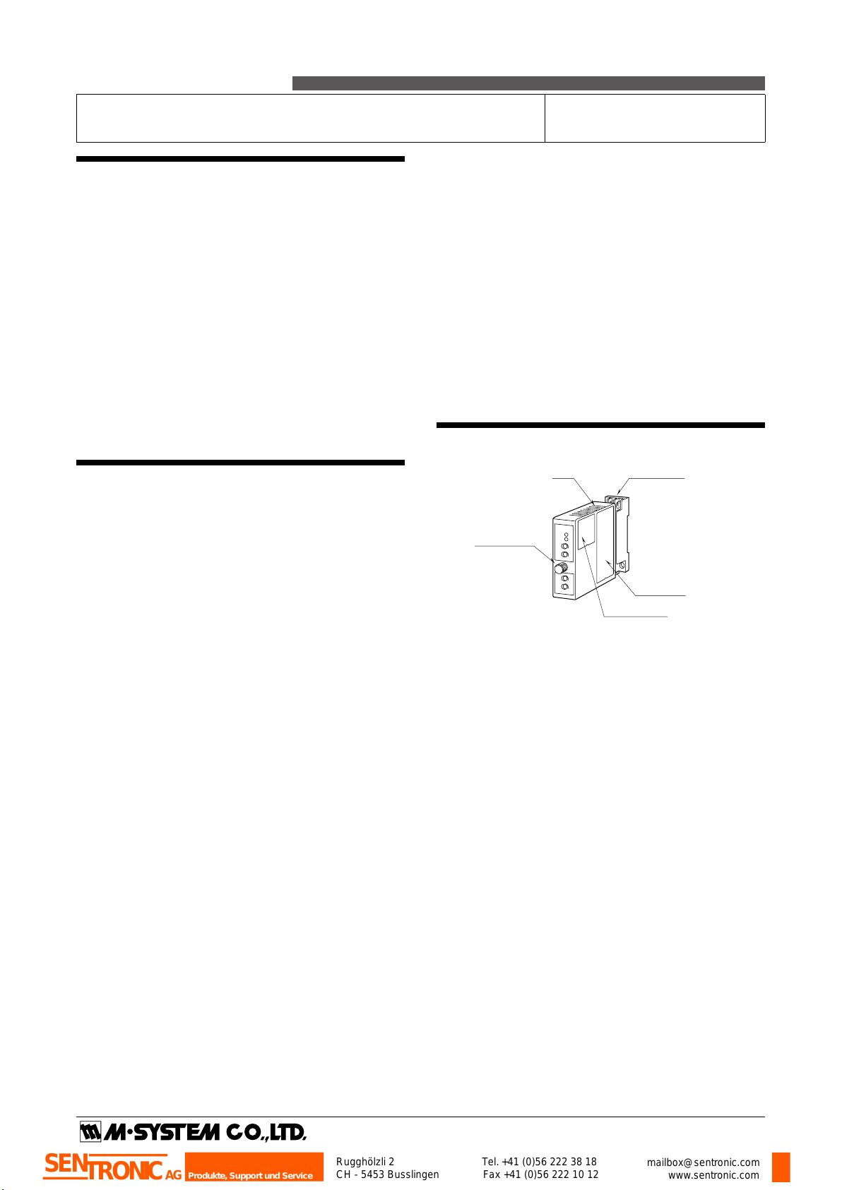
COMPONENT IDENTIFICATION
Model
SPAN
ZERO
INP1
SPAN
ZERO
STAT2
STAT1
INP2
Body Base Socket
Connection
Diagram
Specifications
Fixing Screw
Rugghölzli 2
CH - 5453 Busslingen Tel.+41 (0)56 222 38 18
Fax +41 (0)56 222 10 12 mailbox@sentronic.com
www.sentronic.com
Produkte, Support und Service
SENTRONICAG

M2SES2
P. 2 / 3EM-5098 Rev.1
INSTALLATION
Loosen the fixing screw at the front of the unit in order to
separate the body from the base socket.
■ DIN RAIL MOUNTING
Set the base socket so that
its DIN rail adaptor is at
the bottom. Position the
upper hook at the rear side
of base socket on the DIN
rail and push in the lower.
When removing the socket,
push down the DIN rail
adaptor utilizing a minus
screwdriver and pull.
■ WALL MOUNTING
Refer to the drawings be-
low.
+
–
1OUTPUT
4
9
12
U(+)
V(–) POWER
13
14
+
–
INPUT 1
5
8
+
–
INPUT 2
FRONT VIEW
■FRONT VIEW ■SIDE VIEW
OFF
ON
1234
SW1
Output Function
Setting
Zero Adj. (ZERO1)
Span Adj. (SPAN1)
Zero Adj. (ZERO2)
Status Indicator LED1
Status Indicator LED2
Span Adj. (SPAN2)
Input 2
Input 1
DIN Rail
35mm wide
Spring Loaded
DIN Rail Adaptor
TERMINAL CONNECTIONS
Connect the unit as in the diagram below or refer to the con-
nection diagram on the side of the unit.
■ DIP SWITCH SETTING
Choose the output function: High/Low output, normal output proportional to the input 1, or loop test output of 0%, 50% and
100%.
Set the DIP switch to appropriate positions before turning on the power supply. No change in the switch positions is valid
while the power is supplied.
OUTPUT SW1-1 SW1-2 SW1-3 SW1-4 STAT1LED STAT2LED
High signal (*) OFF OFF OFF OFF ON OFF
Low signal ON OFF OFF OFF ON OFF
Input 1 *1 ON OFF OFF ON OFF
0% *1 *1 ON OFF OFF ON
50% *1 *1 OFF ON Blinking ON
100% *1 *1 ON ON ON ON
*1. ON/OFF position is irrelevant.
(*) Factory setting
Rugghölzli 2
CH - 5453 Busslingen Tel.+41 (0)56 222 38 18
Fax +41 (0)56 222 10 12 mailbox@sentronic.com
www.sentronic.com
Produkte, Support und Service
SENTRONICAG
M2SES2
CHECKING
1) Terminal wiring: Check that all cables are correctly con-
nected according to the connection diagram.
2) Power input voltage: Check voltage across the terminal
13 – 14 with a multimeter.
3) Input: Check that the input voltage is within 0 – 100% of
full-scale.
4) Output: Check that the load resistance meets the de-
scribed specifications.
ADJUSTMENT PROCEDURE
This unit is calibrated at the factory to meet the ordered
specifications, therefore you usually do not need any cali-
bration.
For matching the signal to a receiving instrument or in case
of regular calibration, adjust the output as explained in the
following.
■ HOW TO CALIBRATE THE OUTPUT SIGNAL
Use a signal source and measuring instruments of sufficient
accuracy level. Turn the power supply on and warm up for
more than 10 minutes. Be sure to start with the Input 1
adjustment.
1) Turn all DIP switches to OFF positions. (Selecting High
signal)
2) Set Input 2 lower than 0%.
3) Input 1 ZERO (ZERO1): Apply 0% input and adjust out-
put to 0%.
4) Input 1 SPAN (SPAN1): Apply 100% input and adjust
output to 100%.
5) Check Input 1 ZERO adjustment again with 0% input.
6) When ZERO value is changed, repeat the above proce-
dure 3) – 5).
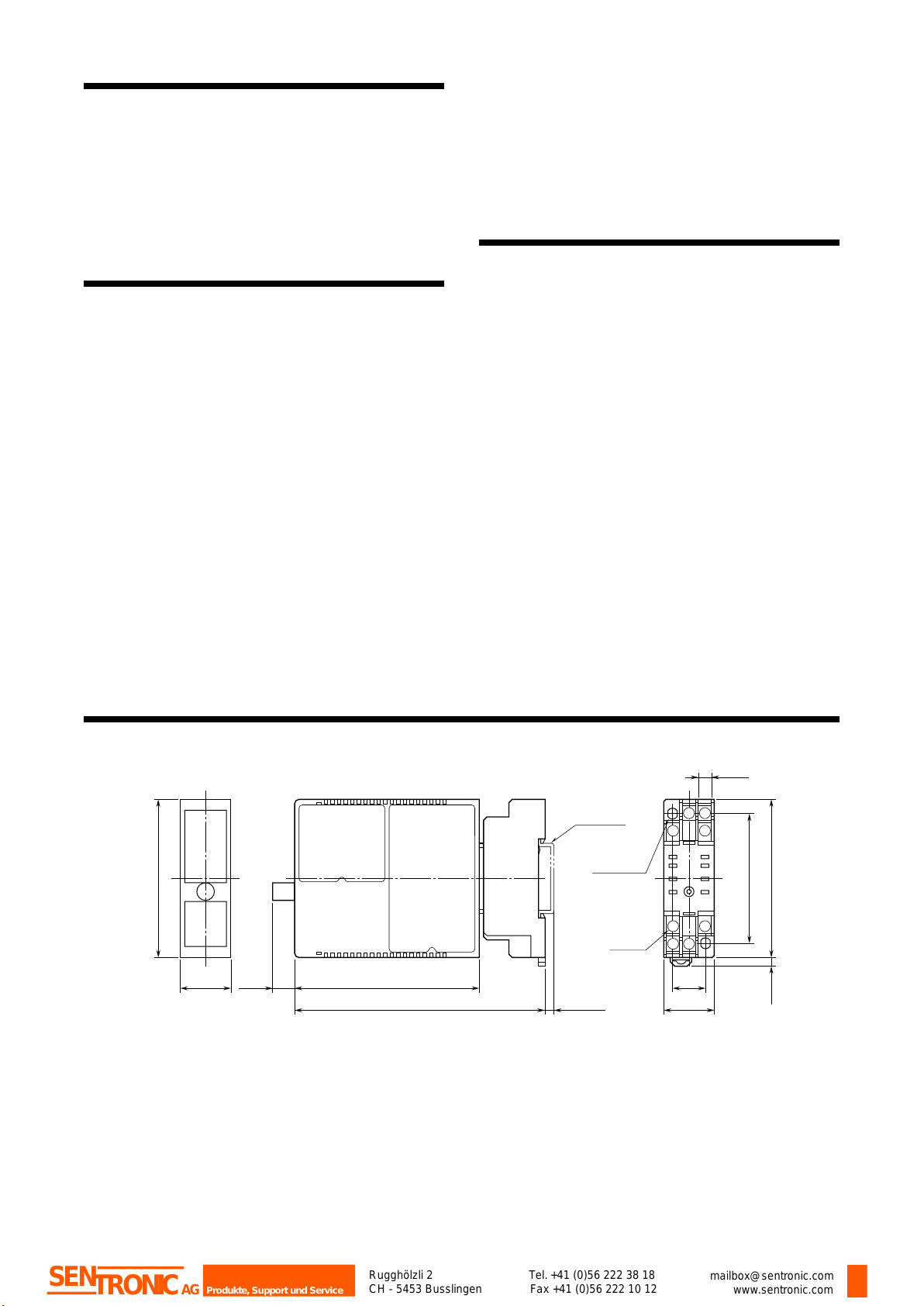
5
9
21.5(.85)
70.5 (2.78)
84 (3.31)10 (.39) 15(.59)
6(.23)
59 (2.32)
DIN RAIL
35mm wide
[4 (.16)]
8–M3
SCREW
72 (2.83)
23 (.91)
2–4.2x5
(.17x.20)
MTG HOLE
6 (.24) deep
114 (4.49)
• When mounting, no extra space is needed between units.
4
8
12
14 13
1
4 (.16)
7) Set Input 1 lower than 0%.
8) Input 2 ZERO (ZERO2): Apply 0% input and adjust out-
put to 0%.
9) Input 2 SPAN (SPAN2): Apply 100% input and adjust
output to 100%.
10
)Check Input 2 ZERO adjustment again with 0% input.
11
)When ZERO value is changed, repeat the above proce-
dure 8) – 10).
MAINTENANCE
Regular calibration procedure is explained below:
■ CALIBRATION
Warm up the unit for at least 10 minutes. Apply 0%, 25%,
50%, 75% and 100% input signal. Check that the output
signal for the respective input signal remains within accu-
racy described in the data sheet. When the output is out of
tolerance, recalibrate the unit according to the “ADJUST-
MENT PROCEDURE” explained earlier.
EXTERNAL DIMENSIONS unit: mm (inch)
Rugghölzli 2
CH - 5453 Busslingen Tel.+41 (0)56 222 38 18
Fax +41 (0)56 222 10 12 mailbox@sentronic.com
www.sentronic.com
Produkte, Support und Service
SENTRONICAG
This manual suits for next models
1
Table of contents


