impro IMPROX XRS902-1-0-GB-XX User manual

MODEL NUMBER: XRS902-1-0-GB-XX
IMPROXREGISTRATION
INTERFACE
ImproX (RS) Registration Interface
INSTALLATION MANUAL
SPECIFICATIONS
Working Environment .................
The ImproX RS is designed to work in an
indoor (dry) environment similar to IP20. The
ImproX RS is, therefore, NOT sealed against
water.
Scanner Operation.......................
125 kHz.
Input Voltage................................
5 V DC Supplied from the USB Port.
Power Requirements
Current (mA)
Power (W)
Maximum Current Drawn from
the USB Port .........................
200
1.0
Third-party Port ...........................
5 V DC 0.1 V is supplied to power the single
Reader connected to this Port. A maximum of
100 mA can be supplied from this Port.
Installer Interfaces
Registration Interface
Power Indicator
Power LED..............
Blue (steady) (externally visible).
Diagnostic Indicators
USB Tx LED............
Red (flashing) (internally visible).
USB Rx LED...........
Green (flashing) (internally visible).
RS485 Tx LED........
Red (flashing) (internally visible).
RS485 Rx LED........
Green (flashing) (internally visible).
ImproX RRA or RRM
Status Indicator
Status LED..............
Bi-colour, Red or Green LED.
Buzzer
Volume and Tone......
Four volume, single tone (Software
dependent).

XRS305-0-0-GB-05
June 2007
Page 2
INSTALLATION INFORMATION
Accessories
Find the following when unpacking the Registration Interface:
An ImproX (RS) Registration Interface housed in a Black, Aluminium extruded
Cabinet. The Cabinet consists of a Top Cover, a Base and two End Plates (each
End Plate is attached with three Thread Cutter Screws (M3 x 8 mm)).
Four Brass Wood Screws (3.5 mm x 25 mm).
Four Wall Plugs (7 mm).
A 1.8 m (5.90 ft) standard USB Cable with a Type A to Type B Connector.
An extra Fixed Address Label.
General
Remember the following when installing the Registration Interface:
FCC Compliance
For FCC compliance:
Ensure the comms cable is routed through a separate grommet to the power
cable.
Ensure that you use a CE approved Power Supply Unit.
Communications Distance
The USB communications distance between the Host PC and the Registration
Interface MUST NOT exceed 5 m (16.40 ft).
DO NOT cut and join the supplied USB Cable. If extension of the USB Cable is
required, source a new longer length USB Cable.
Distance between the Registration Interface and the ImproX RRM or
ImproX RRA
The maximum cable distance between the ImproX Registration Interface and the
ImproX RRM or ImproX RRA, MUST NOT exceed 2 m (6.56 ft).
Mounting the Cabinet
CAUTION: Make certain that you mount the ImproX RS on a vibration-free
surface.
Select the mounting position of the ImproX RS, considering accessibility, routing of
wires and visibility of the externally visible LED.
Secure the Cabinet to the mounting surface, using four suitable screws and wall plugs
(supplied), nuts and bolts or rivets.
Blank Space
XRS305-0-0-GB-05
June 2007
Page 3
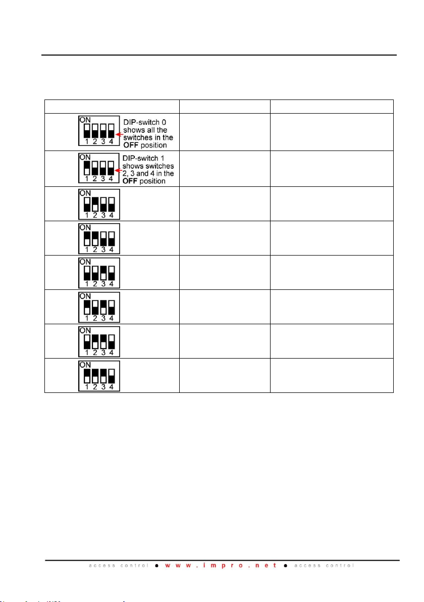
DIP-switch Settings
The format selection for each type of device that can be connected to the Third-party
Port is made by setting the internal DIP-switches as indicated in Table 1.
NOTE: Terminals ‘A’ and ‘B’ in Table 1 are on the Third-party Port Terminal Block.
DIP-switch Position
Format
Connections
0
No peripheral
Reader
N/A
1
Mifare Remote
(ImproX RRM)
Rx to terminal ‘A’
Tx to terminal ‘B’
2
RF Receiver
Data Line to terminal ‘B’
3
Magstripe ABA
Track 2
Data Line to terminal ‘A’
Clock Line to terminal ‘B’
4
Barcode Code-39
with Checksum
Data Line to terminal ‘B’
5
Barcode Code-39
without Checksum
Data Line to terminal ‘B’
6
Wiegand 26/37/40
and 44
0 Data Line to terminal ‘B’
1 Data Line to terminal ‘A’
7
Wiegand Open
Format
0 Data Line to terminal ‘B’
1 Data Line to terminal ‘A’
Table 1: DIP-switch Settings
NOTE: Once the DIP-switch setting is modified reset the ImproX RS to
acknowledge the new settings.
Blank Space


XRS305-0-0-GB-05
June 2007
Page 5
Power-on Self-test
The Power-on Self-test tests the RAM and Flash Checksums.
If any parameter in the Self-test fails, the Registration Reader (i.e. ImproX RRA or
ImproX RRM) emits a continuous beep for 2 seconds.
When the Registration Interface passes the Self-test, the Registration Reader (i.e.
ImproX RRA or ImproX RRM) emits two short beeps, each 200 ms in duration,
separated by a 200 ms inter-beep pause.
Testing the Connection
When you connect the Registration Interface to the PC for the first time, the PC will
prompt you to install the necessary Drivers, once installed, the Power LED will
illuminate Blue (steady).
This confirms the Registration Interfaces connection is correct and working.
Further connections on the same PC will not call for reloading the Drivers.
Fixed Address Label
Keep the Fixed Address Label in a safe place, as you may need the Label at a later
date if you wish to upgrade your Software.
GUARANTEE OR WARRANTY
This product conforms to our Guarantee or Warranty details placed on our Web Site, to
read further please go to www.impro.net.
USER NOTES

XRS305-0-0-GB-05
June 2007
Page 6
USER NOTES

XRS305-0-0-GB-05
June 2007
Page 7
USER NOTES

XRS305-0-0-GB-05
June 2007
Page 8
This manual is applicable to the ImproX (RS) Registration Interface,
XRS902-1-0-GB-01.
(The last two digits of the Impro stock code indicate the issue status of the product).
XRS305-0-0-GB-05
Issue 06
Jun 2007
ImproX RS\English Manuals\LATEST ISSUE\
ImprX RS-insm-en-06.docx
Table of contents
Other impro Recording Equipment manuals

Popular Recording Equipment manuals by other brands


KAHAYAN Proaudio
KAHAYAN Proaudio MIDI SELECTOR 16X8 Operator's manual

Behringer
Behringer Super-X Pro CX3400 user manual

B&G electronics
B&G electronics DAR-04 Installation and operation manual

Fostex
Fostex LIVE RECORDING MIXER LR16 owner's manual

Yamaha
Yamaha CS1D owner's manual

Midi Solutions
Midi Solutions Router operating instructions

Cochlear
Cochlear Baha BP100 user manual

Agilent Technologies
Agilent Technologies 82357B quick start guide

Yamaha
Yamaha PortaSound PSS-12 owner's manual

epiphan
epiphan Lecture Recorder X2 user guide

Walrus Audio
Walrus Audio MAKOSERIES R1 instruction manual

IFM Electronic
IFM Electronic AL1303 operating instructions