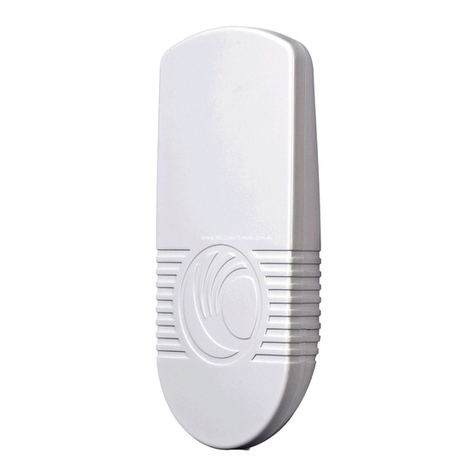
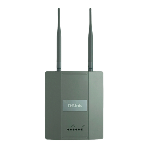
Sentryus WAP-ABG2458 User manual

MD-A
User Manual
Outdoor LAN Access Point
with 1W Amplifier
WAP-ABG2458
FEATURES
Dual Band 2.4GHz/5.8GHz Tri-Mode 802.11 a/b/g
Point-to-Point/ Point-to-Multipoint Wireless Connectivity
Watertight and Weatherproof
64 / 128 / 152-bit WEP Data Encryption
AP, Bridge, Station, and Repeater Modes
Hide SSID (AP Mode)
DHCP Client/ Server
MAC Address Filtering (AP Mode)
Power Amplifier Upgradeable
Web-based Configuration
Power over Ethernet (PoE)
Output Power 2W
Please read the Manual before attempting to use this product.

Copyright © 2012. All Rights Reserved. 2
www.sentryus.com R201204-V27
Disposal of Old Electrical & Electronic Equipment (Applicable in the European
Union and other European countries with separate collection systems).
This symbol on the product or on its packaging indicates that this product shall not be treated as
household waste. Instead it shall be handed over to the applicable collection point for the
recycling of electrical and electronic equipment. By ensuring this product is disposed of correctly,
you will help prevent potential negative consequences for the environment and human health,
which could otherwise be caused by inappropriate waste handling of this product. The recycling of
materials will help to conserve natural resources. For more detailed information about recycling of
this product, please contact your local city office, your household waste disposal service or the
shop where you purchased the product.
CAUTION
1. Handle this product with care
Avoid any shock or bumping of the camera. Improper handling could damage the
camera.
2. Requires a proper operating environment
This camera is designed for indoor use. The allowable temperature range for
operation of this camera is between -4°F ~ 122°F / -10C ~ 50C.
3. Check the power source voltage
The power source voltage should be within the specified range. (Product must
meet the specifications).
4. Objects and liquid entry
Never push objects of any kind into this product as this may touch dangerous
voltage points of short out parts that could result in a fire or electric shock. Never
spill any kind of liquid on the product.
5. Servicing
Do not attempt to service this product by yourself as opening or removing covers
may expose you to dangerous voltage or other hazards. Refer all service to
qualified servicing personnel.

Copyright © 2012. All Rights Reserved. 3
www.sentryus.com R201204-V27
6. Damage requiring service
Unplug this product from the wall outlet and refer service to qualified servicing
personnel under the following conditions:
a. When the power supply cord or plug is damaged.
b. If liquid has been spilled, or objects have fallen into the product.
c. If the product has been exposed to rain or water.
d. If the product has been dropped or the cabinet has been damaged.
e. When the video product exhibits a distinct change in performance.
Note:
The WAP-ABG2458 is intended for professional installation only. This manual,
however, is also designed for personnel who plan, operate and administrate the
WAP-ABG2458 communication system. Please review the entire manual before
powering up or deploying any WAP-ABG2458.

Copyright © 2012. All Rights Reserved. 4
www.sentryus.com R201204-V27
INDEX
OVERVIEW …………………………………………………………………………………………………..………….. 5
PACKAGE CONTENTS …………………………………………………………………………..….……...……….. 5
APPLICATIONS ……………………………………………………………………………………………..……….. 6-7
OPERATION TYPES ………………………………………………………………………………….……….……….. 8
HARDWARE INSTALLATION …………………………………………………………………………..…….. 9-15
TYPICAL DEPLOYMENT IN A POINT-TO-POINT CONFIGURATION ……………………………… 15
SETTING THE BASE STATION UNIT (BU) ……………………………………………………..………. 15-22
SETTING THE REMOTE UNIT (RU) ………………………………………………………….…..……… 22-29
RUNNING TEST …………………………………………………………………………………..……….……. 29-34
MOUNTING LOCATION ……………………………………………………………………………..………. 35-37
SPECIFICATIONS ……………………………………………………………………………………………………… 37
LIMITED WARRANTY ……………………………………………………………………………..……………... 38
APPENDIX A: ACCESS POINT / BRIDGE CONFIGURATION …………………………………… 38-55

Copyright © 2012. All Rights Reserved. 5
www.sentryus.com R201204-V27
OVERVIEW
The WAP-ABG2458 is a powerful answer for customers seeking a reliable high-speed
wireless connectivity solution. It is a 2.4GHz (802.11 b/g ) and 5.8GHz
(802.11a)-compliant Wireless Bridge/AP/AP Client, data delivers 1 to 54 Mbps data
rates without the need for a license.
WAP-ABG2458 can operate as a point-to-point or a point-to-multipoint bridge to link
networks in different buildings. It is particularly suited for financial banks, campus,
store merchants and small business owners to create wireless backbone networks.
System privacy is inherent through the MAC WEP based mutual authentication
functionality by preventing unauthorized intrusion to the radio link.
The WAP-ABG2458 is designed for outdoor environments. With lift-cover watertight
housing, this is a robust Bridge/AP/AP Client, and uniquely designed that Antenna to
integrate with housing. Supplying the power and Ethernet connectivity concurrently
via a single Ethernet cable, the power over Ethernet (PoE) technology makes quick
outdoor installation. WAP-ABG2458 achieves rapid Return On Investment (ROI) for
inter-building connection compared to T1 leased line with high capacity and high
data throughput.
PACKAGE CONTENTS
One (1) Outdoor Unit
Three (3) Mounting Brackets
Four (4) Long Screws
Twelve (12) Washers
Eight (8) Small Screws
Twenty Four (24) Small Washers
One (1) DC Injector
One (1) 48V DC Power Adapter
One (1) Installation CD
One (1) User Manual
For any returns, please include all components listed above with original packaging in
Resalable Condition. Absolutely No Returns will be accepted if any component is
missing/damaged.

Copyright © 2012. All Rights Reserved. 6
www.sentryus.com R201204-V27
APPLICATIONS
Central Office to Branch Office(s) Connection
Medical Hospitals to Medical Hospitals Wireless Connection

Copyright © 2012. All Rights Reserved. 7
www.sentryus.com R201204-V27
Building to Building Connection
Connection between City and Suburb

Copyright © 2012. All Rights Reserved. 8
www.sentryus.com R201204-V27
OPERATION TYPES
There are two different modes in which you can set up the WAP-ABG2458 in the
building-to-building wireless network: Point to Point mode, and Point to Multipoint
mode.
Mode 1: Point-to-Point Connectivity (PTP Mode)
This is the simplest network configuration in which several computers equipped with
the PC cards or client bridges that form a wireless network whenever they are within
range of one another.
Mode 2: Point to Multipoint Mode (PTMP Mode)

Copyright © 2012. All Rights Reserved. 9
www.sentryus.com R201204-V27
HARDWARE INSTALLATION
HARDWARE DESCRIPTION
Outdoor Unit:
A. Two layers silica gel: having double-waterproof
B. EMI prevent wire: To avoid electromagnetic interference
C. Nylon cable gland:IP68; Working Temp:-40°C~100°C
D. Half-screw: Not to fall
E. Panel Antenna:17 dBi gain; SMA connector
F. Access Point/Bridge: IEEE 802.11a -compliant
G. Power over Ethernet (POE) Splitter set: Output 5V DC / 3A
H. Mounting kit: Mounting Bracket on Mast with /U-bolts
* LED on the AP/Bride description:
On the AP/Bridge there are LED lights that inform you of the AP/Bridge’s current
status. Below is an explanation of each LED.

Copyright © 2012. All Rights Reserved. 10
www.sentryus.com R201204-V27
Power
The Power LED lights up and will keep while the AP is powered on.
When the AP goes through its self-diagnostic mode during every
boot-up, this LED will flash. When the diagnostic is complete, the LED
will be lit continuously.
11a
The 11a LED flashes when there is a successful Wireless-A connection.
11b/g
The 11b/g LED flashes when there is a successful Wireless-B/G
connection.
LAN
The LAN LED lights up when Ethernet port of AP was connected
flashing that indicates the network activity over that port.

Copyright © 2012. All Rights Reserved. 11
www.sentryus.com R201204-V27
Indoor Unit: DC Injector
A. Power LED: The Light is green. Power is supplied
B. DATA IN:TO connect PC/Notebook or network
C. P+DATA OUT: TO connect 6803 outdoor unit
D. Power in: TO connect 48vdc adapter
OUTDOOR UNIT INSTALLATION
Step 1: Place the Ethernet cable through the “Nylon cable gland”
1a)

Copyright © 2012. All Rights Reserved. 12
www.sentryus.com R201204-V27
1b)
1c)
1d)
1e)

Copyright © 2012. All Rights Reserved. 13
www.sentryus.com R201204-V27
Step 2: Connect the Ethernet cable to PoE Splitter set
Step 3: Connect the PoE Splitter set to AP/Bridge
Step 4: Connect the Antenna to AP/Bridge
Step 5: Screw the housing

Copyright © 2012. All Rights Reserved. 14
www.sentryus.com R201204-V27
MOUNTING BRACKET ON MAST WITH U-BOLTS
Step 1: Affix pole mounting bracket
Step 2: Affix pivot adapter bracket
Step 3: Affix pole clamp
Step 4: Adjust the angles.

Copyright © 2012. All Rights Reserved. 15
www.sentryus.com R201204-V27
INDOOR UNIT INSTALLATION
TYPICAL DEPLOYMENT IN A POINT-TO POINT CONFIGURATION
SETTING THE BASE STATION UNIT (BU)
PC Configuration –Follow the steps below in order to configure the TCP/IP settings of
your PC.

Copyright © 2012. All Rights Reserved. 16
www.sentryus.com R201204-V27
Step 1: In the Control Panel double click Network Connections, and then double click
on the connection of your Network Interface Card (NIC). You will then see
the following screen.

Copyright © 2012. All Rights Reserved. 17
www.sentryus.com R201204-V27
Step 2: Select Internet Protocol (TCP/IP) and then click on the Properties button. This
will allow you to configure the IP address of your PC. You will then see the
following screen.
Step 3: Select Use the following IP address radio button, and then enter an IP address
and subnet mask for your PC. Make sure that the device and your PC is on
the same subnet.
Step 4: Click on the OK button, your PC’s TCP/IP settings have been configured.

Copyright © 2012. All Rights Reserved. 18
www.sentryus.com R201204-V27
BRIDGE SETUP-WEB CONFIGURATION
Step 5: Logging In –To configure the Bridge through the web-browser, enter the IP
address of the Bridge into the address bar of the web-browser (default IP:
192.168.1.250), and press Enter. If it cannot work, please press the reset
button which is on AP/Bridge. Please see the reference of the enclosed
picture.
Step 6: A screen will be popped up and request you to enter user name and password.
The default user name and password is as follows.
User Name:
Password: Admin
Enter the default user name and password, then press OK button directly.

Copyright © 2012. All Rights Reserved. 19
www.sentryus.com R201204-V27
Step 7: After you login, you will see the following screen.

Copyright © 2012. All Rights Reserved. 20
www.sentryus.com R201204-V27
Step 8: Search Status –Choose the item-Status>Wireless Network. After this step, you
will see the following screen.
Table of contents
