Serai OG/76R User manual

ERA I
S
Gates Automation Division
OG/76R
25.76R
TWO CHANNEL OUTDOOR PLUG-IN "ROLLING CODE" RECEIVER
DAL 1965
1
OG/76R
!
2
Ø 5 ÷ 8mm CABLE GLAND
3
1
ANTENNA
FIXING SCREW
90° clockwise
SUPPORT
POWER SUPPLY
12÷24Vac/dc
123456
RELAY OUTPUT
CHANNEL 1
RELAY OUTPUT
2CHANNEL
NACNAC
~
ac
dc
DESCRIPTION
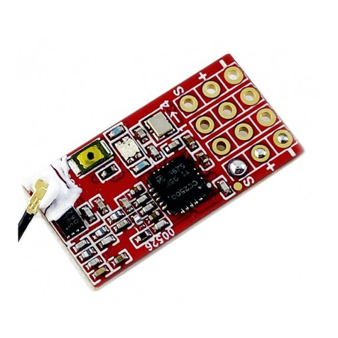
OG/76 R is a 433.92MHz dual channel "rolling code" radio receiver, suitable for outdoor
installation, to be coupled to the corresponding remote control family (OG/2M, OG/4M). The
appliance has a 12 or 24Vac or dc power supply. OG/76 R can store up to 33 different SERAI
rolling code remote controls, regardless of the number of receiver channels commanded by
each one. Another 780 remote controls can be stored by installing the optional SOG/2 A
memory expansion card, for a total of 813 different remote controls memorised. The
transmitters must be associated to the OG/76 R receiver (1 or 2 channels), by means of the
self-learning procedure in order to operate. The behaviour of 2 output relays (NO contact) can
be configured individually as monostable or bistable (memorising the status in case of a power
failure) with specific dip switches. Each channel is equipped with a button to activate self-
learning or for cancelling, and a specific LED which, if on or flashing, indicates its use in
various situations (command reception, self-learning, cancellation, etc.).
INSTALLATION AND CONNECTION
Installation and subsequent operations must be carried out by qualified personnel
according to plant management laws and standards in force, with all power
disconnected. The appliance is belt for indoor or outdoor installation, as long as the cable
gland faces downwards. For installation, release the fixing screw and extract the support (1). It
must be hung on a wall using screws with inserts or blocked tightly (even on poles) using self-
locking nylon clamps; pass the cables through the 2 cable glands fixed to the support (2). After
having fixed the support, make the connections using the removable terminal (3). If you need
to change the default factory settings, proceed with step 4 (from 4a to 4f); for example to
replace the wire antenna with the optional OG/50 antenna which increases the capacity of the
remote controls, to assign monostable behaviour to channel 1 and/or 2 instead of bistable.
Power the appliance, program the remote controls (self-learning procedure) and perform the
functional check, plug it back onto the support (5), secure it with the fixing screw and tighten
the cable gland.
ATTENTION!
There is a main isolation (1500V) between the antenna coming out of the appliance,
which could be accessible, and the power supply and relay contacts. Therefore make
sure that both the power supply to the appliance and the loads piloted by the relays are
isolated from the 230Vac mains by a dual safety isolation (4000V), or at least an
additional isolation (2500V).
CHANGING DEFAULT SETTINGS
OK NO NO
CHANNEL 1
BISTABLE
(STEP-BY-STEP)
CHANNEL 1
MONOSTABLE
(IMPULSIVE)
23
ON
4
1
23
ON
4
1
CHANNEL 2
BISTABLE
(STEP-BY-STEP)
CHANNEL 2
MONOSTABLE
(IMPULSIVE)
13
ON
4
2
13
ON
4
2
REMOTE
PROGRAMMING
DISABLED
REMOTE
PROGRAMMING
ENABLED
1 2
ON
43
1 2
ON
43
REMOTE
CANCELLATION
DISABLED
REMOTE
CANCELLATION
ENABLED
1 2 3
ON
4
1 2 3
ON
4
4b
4c
4a
4d
CONNECTOR FOR OPTION
AL SOG/2 A MEMORY EXPANSION
CARD: PAY ATTENTION TO
CORRECTLY POSITION
THE POLARISATION FOOT
CONFIGURATION
DIP-SWITCHES
4f
P1 SELECTION
BUTTON SOG/2
A CHANNEL 1
SOG/2 A
P2 SELECTION
BUTTON
CHANNEL 2
GND
INDICATOR
LED L2
CHANNEL 2
ANTENNA
TERMINAL FOR CONNECTING
OPTIONAL OG/50 ANTENNA:
CONNECT THE BRAID TO GND
INDICATOR
LED L1
CHANNEL 1
OG/76 R
CARD
4e
OG/76 R
CARD
90°
anticlockwise
5
!
ATTENTION!
Aim the antenna cable downwards,
arranging it in a straight line
without bending or cutting it.
Having removed the support, extract the
printed circuit by grabbing the edge of
the connector with straight pointed pliers
(4e). Change the default settings as
indicated (4f), then put the circuit board
all the way back into the container,
sliding it on the guides. Reposition the
internal plastic side.
4

OG/76R 01 02 20131205 - A4Vf/r 40g/mq - IS OG/76R-E
CE DECLARATION OF CONFORMITY
SERAI srl hereby declares that the OG/76R product was designed and manufactured in full compliance with the above mentioned directives and standards.
2011/65/UE DIRECTIVE ABOUT THE RESTRICTION OF THE USE OF CERTAIN HAZARDOUS SUBSTANCES IN ELECTRICALAND ELECTRONIC EQUIPMENT (RoHS)
2012/19/UE DIRECTIVE ABOUT THE WASTE OF ELECTRICAL AND ELECTRONIC EQUIPMENT (WEEE)
This device was manufactured according to the restrictions set by the RoHS directive. To protect the environment: when no longer needed, the device must not be disposed of as mixed municipal
waste. Take it to an appropriate WEEE (Waste of Electric and Electronic Equipment) waste collection facility.
MADE IN ITALY
VIA ENRICO FERMI, 22
35020 LEGNARO - PADOVA
ITALY
+39 049 79 08 58
+39 049 88 30 529
www.serai.com
ELETTRONICA PADOVA
DAL 1965
WARRANTY CONDITIONS
The company reserves the right to make any modification without prior notice. The conventional SERAI product warranty is valid 24 months following the issuance of the fiscal document attesting to its purchase. Services
covered by the warranty are provided at the company's facilities in Legnaro (PD - ITALY) or at any one of the company's authorized Service Centres. The relative shipping and transport costs are at the Customer's
expense. For TechnicalAssistance call: +39.049.790.858, Monday to Friday 8:30 to 12:30 and 14:00 to 18:00. The warranty shall be retained void in the event of any tampering with the product or in the event that the label
specifying the product's production batch has been broken or removed.
Using a tool guaranteeing dual isolation (by standard 4000V),
shortly press (~1") and release the button of the chosen
channel, P1 or P2. The corresponding yellow LED (L1 or L2)
switches on. The channel is in the self-learning function and
the receiver can now store rolling code transmitters.
1 2 Press the button you wish to associate to the channel in
self-learning on the transmitter being stored. The LED of
the receiver relative to the selected channel flashes briefly
to confirm memorisation and then remains on awaiting
further storing. If the SOG/2 A memory expansion card is
inserted, the LED flashes quickly while searching for a
free position in the memory before storing. Clones of a
transmitter already programmed do not need to perform
self-learning.
ATTENTION!
If storing does not occur when the transmitter
button is pressed, then the transmitter button
you have pressed has already been saved for that
particular channel, the transmitter is faulty or its
battery is flat.
!
3Repeat step 2 to store other transmitters on the same channel (max. 33 or max. 813 if SOG/2 A memory expansion card is
inserted). Briefly press and release the button relative to the selected channel to exit self-learning: the LED switches off.
Self-learning is exited automatically (LEDs off) after waiting 2' without any storing.
ATTENTION!
This procedure cancels all programmed transmitters for the selected channel only. In order to re-program
transmitters in relation to the deleted channel, the self-learning procedure must be performed again.
!
CANCELLATION PROCEDURE OF TRANSMITTERS ASSOCIATED TO A CHANNEL (CHANNEL CANCELLATION)
ATTENTION!
The status of the configured bistable outputs is stored inside the appliance at each switchover. The relays go
to the rest condition (not energised) if power is disconnected; when power returns, they go back to the last
status they were in when the appliance was powered, re-energising.
!
ATTENTION!
During the remote control self-learning
procedure, we recommend temporarily
disconnecting the antenna from the receiver to
avoid unintentionally programming other SERAI
rolling code devices running in the vicinity.
Reconnect the antenna at the end of the
operation.
SELF-LEARNING PROCEDURE TO PROGRAM/ADD TRANSMITTERS TO A CHANNEL
!
Using a tool guaranteeing dual isolation (by standard 4000V), press and hold the button of the chosen channel for at least 5"
until the relative LED starts to flash quickly (cancellation in progress). Release the button. Cancellation takes longer if the
SOG/2 A memory expansion card is inserted and if it is full. Upon completing cancellation, the LED stays on steadily, in self-
learning mode for the channel just cancelled. Proceed from point 2 of the above procedure.
COMPLETE RESET OF OG/76 R RECEIVER AND OF SOG/2 A MEMORY EXPANSION CARDOPTIONAL
(CANCELLATION OF ALL STORED REMOTE CONTROLS)
To completely cancel the memory of the receiver (all channels), including the SOG/2 A memory expansion card,optional if
installed, with just one command, disconnect power to the appliance, press buttons P1 and P2 simultaneously and switch
power back on. Both LEDs start to flash quickly: release the buttons. At the end of the reset operation, the LEDs switch off and
you can proceed with programming from point 1 of the procedure shown above.
TECHNICAL DATA
Power supply voltage: ............................... V c12÷24 a /dc ± 10% 50/60Hz
Maximum consumption: ..........................50mA@12Vdc, 69mA@24Vdc
...............................................................86mA@12Vac, 111mA@24Vac
Frequency 433.92MHz/ channels / 2:.......................................................
Reception distance in free space: ............................................................
.............................................................100m with wire antenna supplied
........................200m with optional OG/50 antenna on dedicated terminal
Outputs 2 relays, each with 1 NO contact max. 5A@30Vac/dc: .................
Cable gland:.......................................................2 x PG9; cable ø5÷8mm
Wiring on removable terminal: .................................................................
..............................................use wires with max. 2.5mm2 cross-section
Maximum dimensions (Lx H x P): ................................... x x mm57 110 48
Weight: ............................................................................................ g110
Shell material ABS - UV protected:............................................................
Protective rating of container mounted properly: ..............................IP 54
Operating temperature: °C........................................................-10 ÷ +60
Storage temperature: - 0°C........................................................... 20 ÷ +7
Maximum relative humidity without condensat: 95%............................ ion
Install the appliance in the complete absence of mains voltage.
Make sure that the power supplied to the appliance is separated from the
230Vac mains by a dual isolation. No particular maintenance is required.
PRODUCT CATEGORYAND INTENDED USE
Electronic, non-automatic device, for use in residential, commercial and light industrial
environments, designed to receive and actuate by relays a control signal in radio frequency, for
each of 2 channels. Its use is exclusively intended to be coupled to SERAI rolling code remote
controls to control utilities.
DIRECTIVES
Low voltage directive (LVD) EC: ...................................................................................2006/95
Electromagnetic compatibility directive (EMC) 2004/108/EC: ...................................................
Directive on radio and telecommunications terminal equipment (R&TTE) 99/5/EC:...............19
Directive on Restriction of Hazardous Substances (RoHS) 20 / 5/: ................................... 11 6 UE
GENERIC STANDARDS
European electrical safety standard:......................................................................EN 60335-1
European EMC standard - immunity: ..................................................................EN 61000-6-1
European EMC standard - emissions ................................................................ 61000-6 3EN -:
European R&TTE standards (SRD): .......................EN 300220-1+EN301489-1+EN301489-3
SPECIFIC PRODUCT STANDARDS
Non-automatic control devices for fixed electrical installation: 669 1................................EN 60 -
It is the installer's responsibility to comply with all the recommendations contained in
this instruction manual, as well as with standards and laws relevant to the plant to be
installed, even if not specified herein.
Other Serai Receiver manuals
Popular Receiver manuals by other brands

Kathrein
Kathrein UFD 430 operating manual
Sony
Sony STR-DA5800ES operating instructions

BroadcastVision
BroadcastVision FITNESS CINEMA Operation manual
Harman Kardon
Harman Kardon AVR 7500 Service manual
Leica Geosystems
Leica Geosystems GS14 user manual
Lectrosonics
Lectrosonics SR175 Operating instructions and troubleshooting guide


