Seres OL TOPAZ User manual

User manual
TOPAZ
N°10851-EN_rev H

2
Environmental conditions
Temperature : 5°C to 40°C
Relative humidity : 10% to 80%
Pollution level : 2
Installation category : II
Altitude : max 2000m
Installation precautions : sheltered from bad weather, humidity, corrosive
surrounding and dust
Do not use this equipment in hazardous area (presence of flammable liquids,
gases…), it could represent safety hazard.
Physical/Electrical characteristics
PRODUCT
TOPAZ / CRISTAL / ONYX / SERES 2000E
Dim : w*h*d (mm*mm*mm)
480*750*320
Fixation
Wall mounted with 4 screw-bolts M8 (PC panel at operator eye level to
simplify maintenance)
Power supply / section
100~240 V, 50/60 Hz, max 3 mm², unscrew right side to connect cable
(cable gland 7.5 to 13 mm and 13 to 19mm)
Power consumption
Typically 150 VA - Maximum 300 VA
Input/Output wire section
Max 1.5 mm²
Protection
IP55
Hydraulic requirements
Sample clean and clear
Particles<100µm, filtered if necessary
Inlet (sample/dilution water) : optimal flow /
max pressure / connection
4 to 40 l/h ; <3 bars ; ¼’ female BSP
Overflow : 8*12mm flexible tube
Sample temperature
< measuring temperature (depend on method)
Waste outlet / connection
Free not closed ; 12*14 mm flexible tube
Air input (on demand) / connection
Blowing of the apparatus (filtered, clean and dry air, min
flow of 200l/h) ; 6 mm tube
Table of contents
Environmental conditions..........................................................................................2
Physical/Electrical characteristics .............................................................................2

3
Hydraulic requirements .............................................................................................2
1. Revision list..........................................................................................................4
2. Warranty conditions / Before installation.........................................................4
2.1 General terms ...............................................................................................4
2.2 Regulations...................................................................................................4
2.3 Handling precautions....................................................................................5
2.4 Manual update..............................................................................................5
2.5 Access level..................................................................................................6
3. Input/Output connections...................................................................................6
3.1 Input .............................................................................................................6
3.2 Output...........................................................................................................7
3.3 Inputs wiring ................................................................................................8
3.4 JBUS connection..........................................................................................9
4. Operating instructions......................................................................................10
4.1 Start-up.......................................................................................................10
4.2 Reagents installation...................................................................................13
4.3 Starting the analyser ...................................................................................13
4.4 Pump priming.............................................................................................13
4.5 Control mode setting ..................................................................................14
4.6 Scheduler....................................................................................................14
4.7 Launching continuous cycles .....................................................................15
5. Maintenance instructions .................................................................................15
5.1 Electrode slope control (potentiometric method only) ...............................15
5.2 Electrode slope control for analyzer with dilution (potentiometric method
only) 16
5.3 Electrolyte level check (potentiometric method only)................................16
5.4 Calibration (whole methods) ......................................................................16
5.5 Calibration for analyser with dilution module............................................18
5.6 On-line calibration......................................................................................18
5.7 Manual measure (whole methods)..............................................................18
5.8 Manual measure for an analyser with dilution ...........................................19
5.9 Cleaning Cycle-Option...............................................................................19
5.10 Specific maintenances (Ca/Mg in brine analyser)......................................20
5.11 Specific maintenance (Color).....................................................................21
5.12 Replacing reagents (whole methods)..........................................................21
5.13 Pumps tube (whole methods) .....................................................................22
5.14 Automatic maintenance cycle (Option)......................................................24
5.15 Data visualization and downloading...........................................................24
5.16 Switching off the analyser..........................................................................26
6. Alarms................................................................................................................27
7. Troubleshootings...............................................................................................29
8. Standards...........................................................................................................31

4
1. Revision list
Revision
Description
Written by
Approved by
On :
A
First release
B.TIGRINE
E.MEUNIER
04/07/2017
B
Standards/contacts update
L.CARIS
L.CARIS
26/10/2018
C
Drawing update + input/output table + slope control
L.CARIS
L.CARIS
18/12/2018
D
--
L.CARIS
L.CARIS
17/01/2020
E
Add drawing installation
N.DALIA
N.DALIA
10/2020
F
Drawing and Certificate updates
L.LENOBLE
N.DALIA
02/2021
G
Declaration of conformity update
L.LENOBLE
N.DALIA
08/2021
H
Update document
L.LENOBLE
L.LENOBLE
01/2022
2. Warranty conditions / Before installation
2.1 General terms
General terms of warranty are applied to this analyser and integrated in our general terms
of sale downloadable on SERES OL website:
-One year warranty (spare parts and workshop service) within the framework of
normal operating conditions and maintenance specified in this manual.
-Normal operating conditions. Follow up reagents preparation instructions
supplied by SERES OL guarantees analyser proper working. In case of non-
compliance of these instructions Manufacturer reserves the right to refuse the
one-year manufacturer warranty for the supplied apparatus.
2.2 Regulations
2.2.1 Safety regulations
To avoid people injury caused by electricity, please respect all the safety regulations of
this manual:
-Apparatus should be used exclusively with a ground plug. If the equipment is
used in a way not specified by the manufacturer, the protection provided with
the equipment can be affected.
-Any spare part has to be replaced exclusively by a qualified technician using
only parts specified by the manufacturer.
-All power supplies have to be switched off before dismounting or replacing
any component.
-For any intervention on the hydraulic part of the analyser, wear adapted
protections (protective clothing, gloves, and glasses).

5
-Do not use this equipment if there is flammable liquids or vapours, this could
represent a safety hazard.
2.2.2 Local regulations
All wirings and connections (electrical, hydraulic …) should be done according to local
regulations of the country in force and only by qualified authorized and skilled personal.
The equipment warranty won’t be guaranteed by the manufacturer in case of non-
compliance of the standards and regulations reported in this manual.
2.2.3 International symbols used
Symbol
Standard
Description
IEC 60417, No. 5016
Electrical fuse
IEC 60417, No. 5017
Ground
IEC 60417, No. 5021
Equipotentiality
IEC 60417, No. 5032
Alternative current
IEC 60417, No. 5041
Be careful, hot surface
ISO 3864, No. B.3.1
Be careful, see documents
ISO 3864, No. B.3.6
Be careful, electrical hazard
2.3 Handling precautions
-Position the box correctly (Up/Down)
-Carefully unpack analyser
-Check equipment for damages
If the device seems to be damaged, don’t plug it and get into touch with the After Sale
Service Department immediately.
2.4 Manual update
Information contained in this manual may be subject to change without notice
beforehand and don’t represent any engagement on behalf of Manufacturer.
Manufacturer reserves the right to make changes in the construction, design,
specifications, and / or in the procedures that cannot be reflected in the manual.
This manual is supplied under the condition that the provided information will not be
used to the detriment of Manufacturer.

6
Access level
User access: consultation of the data in the main window.
Access by user with Authority: consultation of measurements in progress, Activation
or Deactivation of a path, Calibration, Interruption of measurement in progress,
adjustment of 4-20mA outputs. CODE=0712
Without action for 10 minutes, the code will be requested again.
3. Input/Output connections
3.1 Input
Name Fonction Name Fonction …Name Fonction
IN_DIG1(4) Selection channel1 IN_DIG3(4) Selection channel2 …IN_DIG(2*N+1)(4) Selection channelN
IN_DIG2(4) Stop End of Cycle IN_DIG4(4) N.U. …IN_DIG(2*N+1)(4) N.U.
Analog
1IN_ANA1(5 N.U. IN_ANA2(5) N.U. …IN_ANA (N+1)(5) N.U.
(4) Possible configurations: dry contact input or 0-24V, (5) 4-20mA type input.
Chart 2
…
(Adress : 2)
Input
TOR ou 0-24V
2
Chart 1
(Adress : 1)
Direction
Type
Nbre per card
Chart N
Adress N (N>3 et <8)

7
3.2 Output
Name Fonction Name Fonction …Name Fonction
OUT_ANA1 (1)
4/20mA Track
measurement 1
OUT_ANA3 (1)
4/20mA Track
measurement 2
…
OUT_ANA
(2*N+1) (1)
4/20mA Track
measurement N
OUT_ANA2 (1) 4/20mA Reserve OUT_ANA4 (1) 4/20mA N.U. …
OUT_ANA
(2*N+2)
4/20mA N.U.
OUT_DIG1(2)
C.S. Reserve
(Watchdog)
OUT_DIG9(2) C.S. N.U. …
OUT_DIG(8*N+1)
(2)
C.S. N.U.
OUT_DIG2(2) C.S. waterfall track 1 OUT_DIG10(2) C.S. waterfall track 2 …
OUT_DIG(8*N+2)
(2)
C.S. Water fault
track N
OUT_DIG3(2)
C.S. Override
threshold 1 track 1
OUT_DIG11(2)
C.S. Override
threshold 1 track 2
…
OUT_DIG(8*N+3)
(2)
C.S. Threshold
overrun1 channel N
OUT_DIG4(2)
C.S. Override
threshold 2 track 2
OUT_DIG12(2)
C.S. Override
threshold 2 track 2
…
OUT_DIG(8*N+4)
(2)
C.S. Threshold
overrun2 channel N
OUT_DIG5(2)
C.S. Channel 1 being
analyzed (multi-
channel)
OUT_DIG13(2)
C.S. Channel 2 being
analyzed (multi-
channel)
…
OUT_DIG(8*N+5)
(2)
C.S. Channel N
being analyzed (multi-
channel)
OUT_DIG6(2) C.S. Defect Analyzer OUT_DIG14(2) C.S. N.U. …
OUT_DIG(8*N+6)
(2)
C.S. N.U.
OUT_DIG7(2)
C.S. Maintenance
Information
OUT_DIG15(2) C.S. N.U. …
OUT_DIG(8*N+7)
(2)
C.S. N.U.
EVTrack 1 Control EVTrack 2 Control EVTrack N Control
(Multipath) (Multipath) (Multipath)
(1) Possible configurations: 4-20mA, 0-1V, 0-10V
(2) Digital contact dry output. Type NO or NC
(3) Output Power Solenoid valve.C.S. = Dry contact (configurable NO / NC) US =Not used
…
OUT_DIG(8*N+8)
(3)
…
Chart N
Address N (N>3 and <8)
Output
Analog
2
Digital (All or None)
8
OUT_DIG8(3)
OUT_DIG16(3)
Direction
Type
Nbr per card
Chart 1
(Address : 1)
Chart 2
(Address : 2)

8
3.3 Inputs wiring
Standard Terminal Drawing
Caution : Specific terminal drawing may be supplied upon method or customer request
3.3.1 4-20mA output wiring:
4-20mA outputs representing chemical value of the measured parameter by analyzer are
accessible for each channel on pins 1 & 2 of connector J7 of the concerned card (card 1
channel 1, card 2 channel 2 etc.).
Pins 3 & 4 are used if there is a second measurement on the same channel
(OUT_ANA2).
The signal value 4mA corresponds to low range measurement (usually 0), and the 20mA
signal value corresponds to high range measurement.
3.3.2 Channel input (IN_DIG1) wiring
Available on each channel map, this input allows remote control of channel selection.
If you do not wish to remotely control the channel selection, leave pins 1, 2 and 3 of J8
unconnected.
There are two wiring modes for this input: dry contact or hot input (0-24V).
It is strongly recommended to use dry contact control to avoid electrical problems. In
this case, connect the 2 terminals of the dry contact to pins 1 & 2 of J8. If the contact is
open, then the channel is selected, if the contact is closed then the channel is

9
invalidated and the corresponding measurement will not be performed. An alert
message (ex : 'Inactive channel (remote control)') will instantaneous appear on the PC
panel at the time this channel should be analysed.
In the case where the control is provided by a 'hot' input 0-24V, the reference must be
connected to pin 3 and the selection voltage 0 / + 24V to pin 2 of J8. Terminal 1 must
always remain unconnected.
3.4 JBUS connection
Communication between analyzer and customer use JBUS protocol. It can be done
either by RS485 or TCP / IP (Ethernet).
3.4.1 JBUS by RS485
JBUS terminal box is installed in the top of the analyzer close to the power supply and
I/O card. Proceed like below:
-Open the door
-Connect the RS485 wires to the JBUS box:
JBUS terminal box
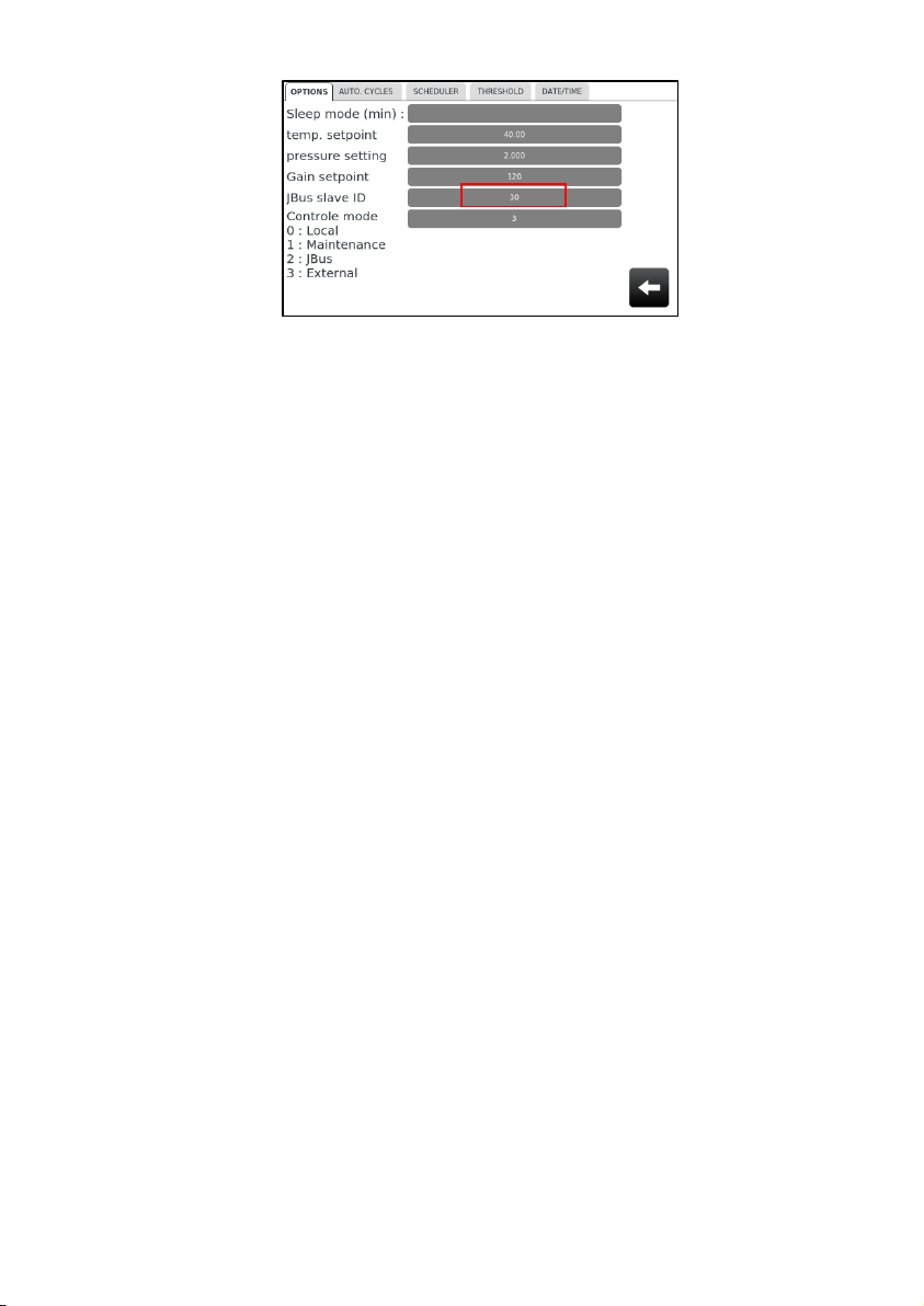
-Set up the JBUS Slave (Maintenance menu/Options menu/ and select Options
tab) : fix a value greather than 16
10
3.4.2 JBUS by TCP/IP
To connect analyzer via Ethernet, the analyzer is equipped with a converter located at
the top of the device.
The connection is made via the Ethernet connector located outside on the right
side of the analyzer.
Simply mount the Ethernet cable in the connector and plug the connector.
For this communication, it is necessary to know the addressing mode desired by
the customer. This is important because the module must be configured correctly.
There are two addressing modes:
-Automatic IP address assigned by a DHCP system to the analyzer
-Fixed IP address (provided by the customer) which had to be configured by
manufacturer
4. Operating instructions
4.1 Start-up
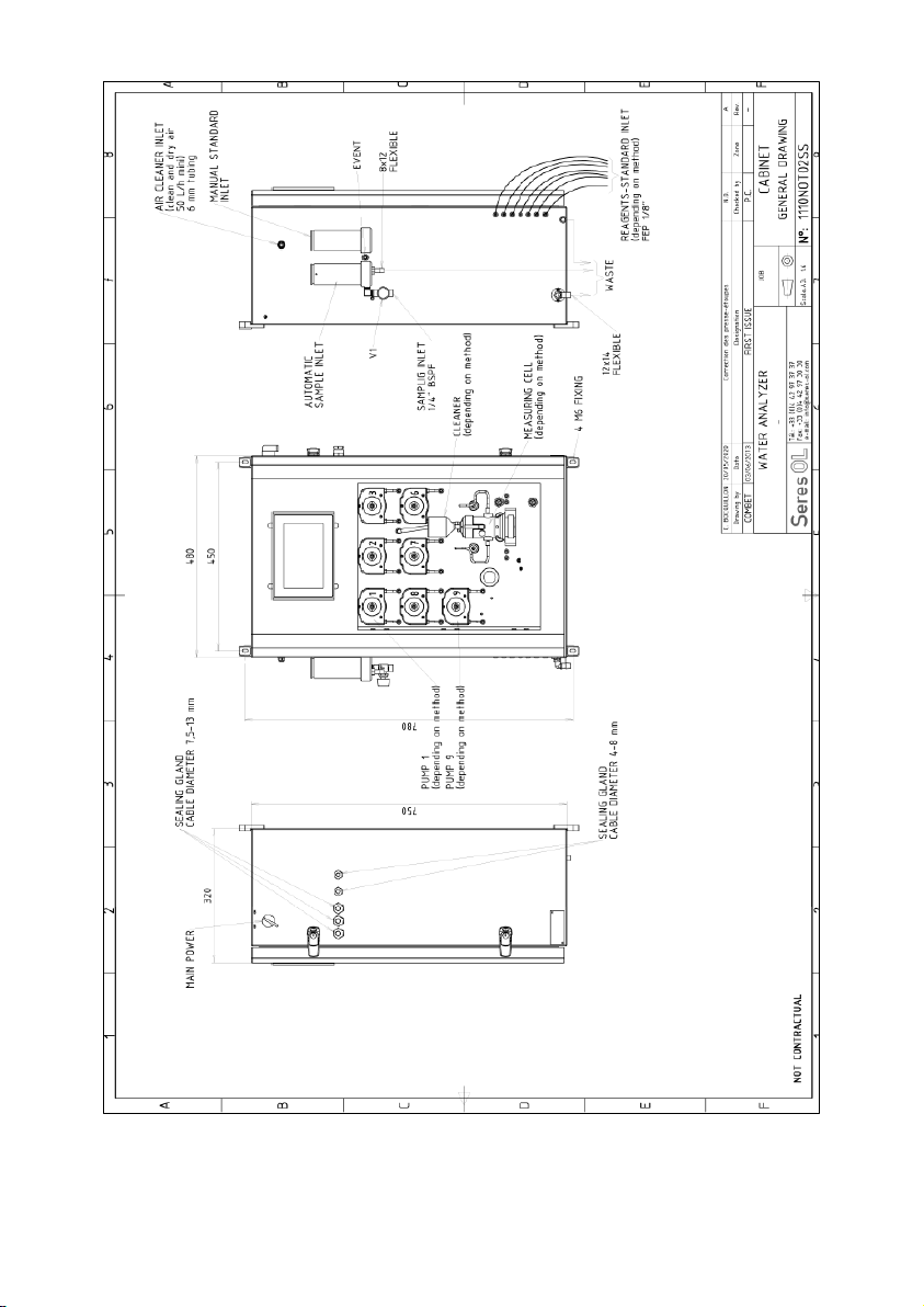
Before connecting the analyzer to the power supply, check all the electric and hydraulic
connections. Eventually, consult "technical specifications" chapter. Adjust the sample
flow so that there is an excess of water at the pressure reducer device (setting tap and
transparent pressure reducer device situated on the left side of the device). If the internal
distribution block is installed, verify that the sample overflows the down flow weir of
the internal distribution block's selection finger.
11
General drawing –1 channel.

12
General drawing –Multichannel.

13
4.2 Reagents installation
Reagents have to be stocked out of the analyzer, on the shelf situated nearby. A support
could be supplied to put them on (on demand).
Some reagents have to be stocked sheltered from light. They are stocked in tainted flasks
or black flasks.
To install reagents cans, you should wear appropriate protections (gloves, protective
glasses and clothes). Proceed like below:
-See device hydraulic drawing in order to identifying reagent/pump couples
-Introduce reagent pipes until the bottom of each reagents can. Check the
presence of an air inlet (a small opening in the cap is enough).
4.3 Starting the analyser
Launching of the device is done in an automatic way during the switching on:
-Switch on the device;
-Pumps readjust themselves automatically;
-The PC panel starts;
-An information screen appears and displays the different steps of the starting
up;
-An initialisation window appears;
-The PC Panel launches itself and measuring cycles start automatically;
-Stop the measuring cycle which is just started (press the key ) ;
-Enter the User Code with authority (Access Code: 0712) ;
-A message appears asking you to confirm that the current measurement is
stopped, press OK.
4.4 Pump priming
To prime the reagents, from the main screen:
-Check that the automatic filling pot is overflowing (sample or neutral water
depending on the configuration): it is necessary to flush the vessel;
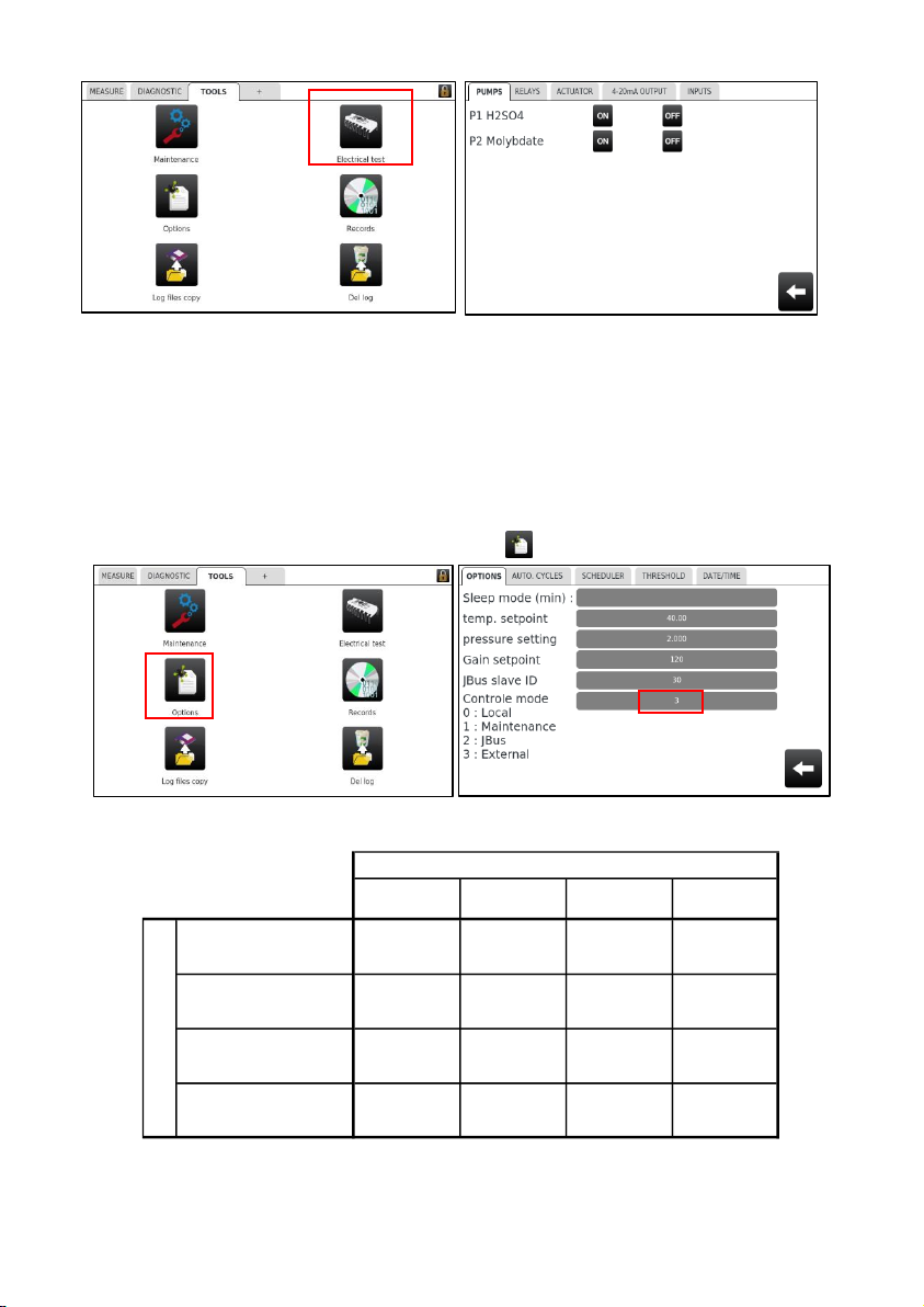
-Press on Tools tab
-Enter the User Code with authorization and press on “valid”
-Go to the menu Electrical test
14
-Press on the pumps tab
-Emptying SV is automatically open (if not go to actuator tab to open it)
-Press ON to activate pumps
-Check if the reagent are well injected into the vessel watching the tubes
-At the end of reagent priming, stop the pumps
4.5 Control mode setting
To set the control mode:
-Press on TOOLS tab; Press on Options
-Enter 0, 1, 2 or 3 following the table below depending on the chosen mode:
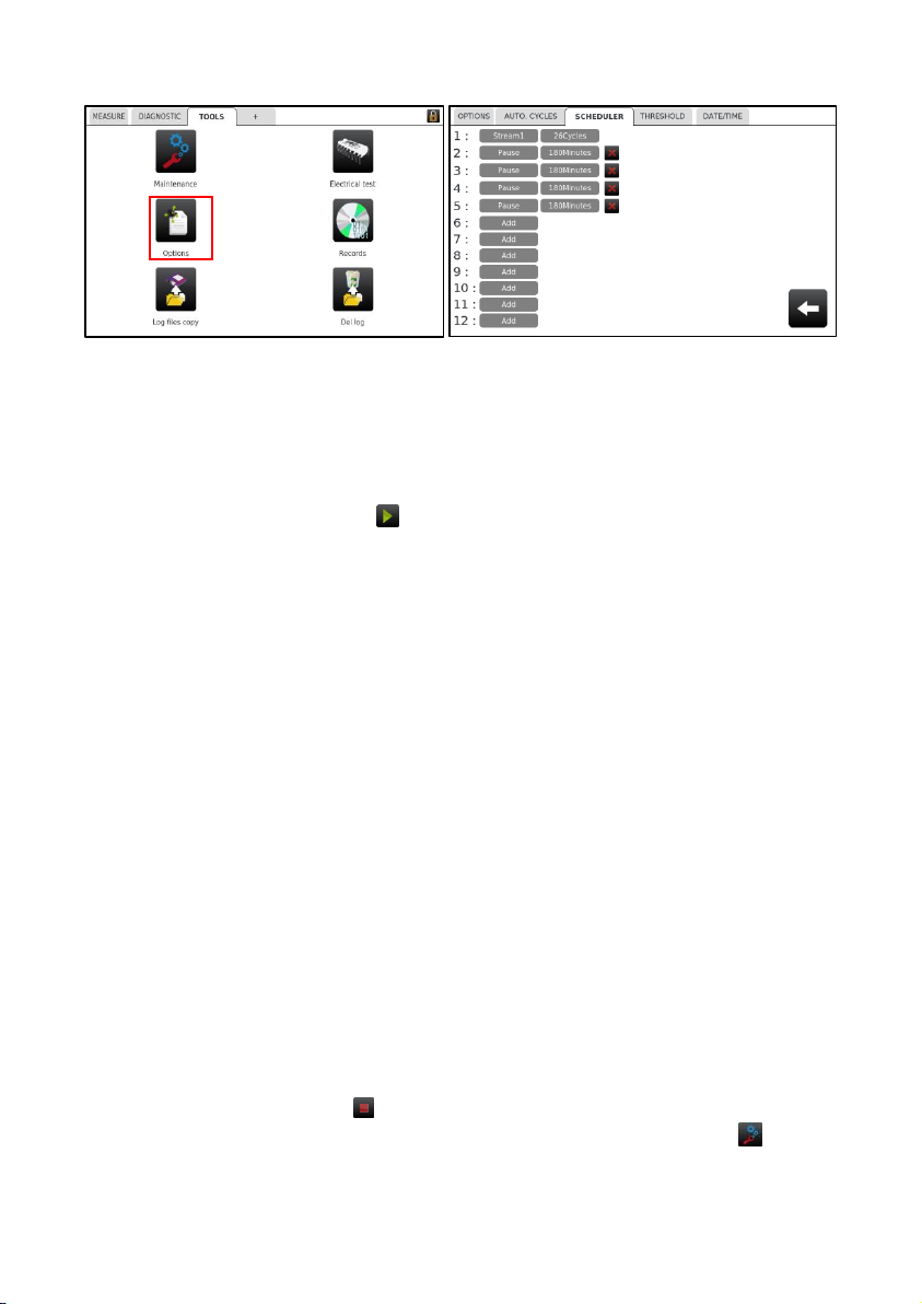
4.6 Scheduler
It is possible to schedule the measuring cycles, from the main screen:
RELAYS 4/20 mA
REMOTE
inputs
JBUS
LOCAL0ACTIVATED ACTIVATED
FROZEN
(Stop/start on
keyboard)
WRITING
MAINTENANCE 1ACTIVATED FROZEN FROZEN WRITING
JBUS2ACTIVATED ACTIVATED FROZEN
READING
WRITING
REMOTE CONTROL3ACTIVATED ACTIVATED ACTIVATED WRITING
OUTPUTS
MODE
15
-Press on Tools tab ; go to the menu Options and press scheduler tab
-Press the "Channel" or "Add" button to change or add a channel number;
-Enter the number of cycles in the new window;
-It is possible to add a pause time in minutes, press "Add", select "Pause" and
enter the number of minutes.
4.7 Launching continuous cycles
To start an on-line analysis, press on the main screen.
5. Maintenance instructions
Analyzer requires few preventive maintenances but it is important to keep it perfectly
clean. These maintenances mainly consist in:
-analyzer calibration / manual measure (monthly),
-reagents replacement followed by calibration. Check vessel, internal distributor
block (if there is one) and silicone tubing cleanness.
-peristaltic pump piping replacement (3 months)
-complete overhaul of all the sub-assemblies for cleaning and inspection
(annual).
-silicone pipe replacement is recommended (annual).
-electrode slope control (1 week automatically) (for potentiometric method
only)
-electrode membrane replacement (approximately 6 months but periodicity
depend on application) and electrolyte level check (monthly) (for
potentiometric method only)
-electrolyte level check and readjustment for reference electrode (if present,
monthly) (for potentiometric method only)
5.1 Electrode slope control (potentiometric method only)
From the main screen:
-Stop the current cycle ; Enter the User with Authority code again;
-On the main screen display, press "Tools" tab; Press Maintenance ,
-Fill or check DIW level in the bottle
-Start the "Electrode Slope Control" program by pressing.

16
Slope check is correct:
oCalculated slope is displayed with current and electrode reference slope,
oPress to return to the Maintenance window;
Slope check is incorrect:
oCalculated and current slope are displayed, with the message "Slope default",
oThe new parameters will not be updated. Restart electrode slope control.
Control of electrode slope is periodically programmed by manufacturer or by HMI.
5.2 Electrode slope control for analyzer with dilution (potentiometric method
only)
For an analyzer with dilution, the electrode slope control cycle is working automatically
with the dilution water.
5.3 Electrolyte level check (potentiometric method only)
Every month check reference electrode/measurement electrode electrolyte level. Adjust
if necessary (follow electrode manufacturer instructions, documents are supplied).
5.4 Calibration (whole methods)
Caution: for multistream analyser with common range, only calibrate stream n°1.
oTO MAKE ZERO CALIBRATION (depending on method),
-Launch « Calibration Zero » cycle instead of the « Calibration » cycle
protocol is similar to the calibration one described hereafter.
-Use some water (same de-ionised water (or neutral water) used to prepare
the standard) instead of the standard solution.
-At the end of the calibration zero, a window displays old and new offset.
oTO MAKE A CALIBRATION :
-Stop the cycle in progress (from the main screen, press on )
-Enter the User code with authorization and press on Valid;
-Press on TOOLS tab ; Press on Maintenance ;
-Press Calibration , a windows called « standard value» appears;

17
-Check « Standard Reference » value and modify it if necessary (be careful to the
concentration unit).
oPress on the value ;
oEnter a new value ;Press on OK and Valid to quit;
-When the message “Pour STANDARD solution” appears, fill 2/3 of the calibration
device (on the analyzer left side) with the Standard solution;
-Wait until calibration device is empty, the message “Vessel filling” is displayed;
-Repeat this action as many time as it is requested;
-Measure is launched automatically;
-Rinse at the end of the measure following instructions (as explained above) on
request;
Calibration is correct (coefficient calculated <current coefficient +/- 50%):
-A screen displays the previous and the new calibration coefficient ;
-Validate, it is automatically saved;
-Quit and come back to the main window;
Calibration is not correct:
-A window displays the message « Calibration failure » and it is not possible
to validate ;
-New parameters won’t be updated. Restart calibration.
Calibration can be scheduled in order to being launch periodically.
VESSEL FILLING

18
5.5 Calibration for analyser with dilution module
To launch zero calibration or calibration cycles, the protocol is similar as 5.2.3
Calibration.
At the beginning of the cycle, the standard is taken from the standard bottle thanks to
the dilution pump. Follow the instructions on the screen:
-Put the tube in the standard solution ; press
-Turn the STANDARD/SAMPLE valve on position STANDARD (if
necessary) and press
-Calibration is launched
-At the end, put back valve on SAMPLE position (if necessary) and press
Calibration can be scheduled in order to being launch periodically.
Manual measure with dilution module follows same protocol.
5.6 On-line calibration
On-line calibration is realized directly by the sampling line. Sample concentration used
as Standard is usually determined in an analytical laboratory.
Launch Calibration cycle without turning the valve STANDARD/SAMPLE.
Caution : if zero calibration is necessary, it had to be realized before on-line
calibration.
5.7 Manual measure (whole methods)
« Manual measure » program is used to determine standard/sample concentration.
This is usually used in cases when chemical method requests some measures before
giving out a significant result. In this case, one or some manual measures are then
realized before calibration to obtain a correct calibration coefficient.
From the main screen of the HMI:
-Stop the cycle in progress ;Enter User code;
-Go to the tools tab; Press on Maintenance ;
-Launch Manual measure by pressing on
-"Add standard" appears, fill the standard device (located on the left of the
analyzer) by 2/3 with standard solution ;
-Wait for the device emptying, the message «Vessel filling » appears
-Repeat this action as many times as it is requested ;
-Then the measure is launched ;

19
-Rinse at the end of the cycle following instructions as it is requested ;
-A window displays measured concentration under the name of manual
measure ;
The signal (Bf=before) indicates the previous manual measure value.
5.8 Manual measure for an analyser with dilution
To launch manual measure, the protocol is similar as 5.2.6 Manual measure.
At the beginning of the cycle, the sample is taken from the sample bottle thanks to the
dilution pump.
Follow instructions on the screen:
-Put the tube in the standard solution and press
-Turn the STANDARD/SAMPLE valve on position STANDARD (if
necessary) and press ; manual measure is launched
-At the end, put back valve on SAMPLE position (if necessary) and press ,
manual measure is completed.
5.9 Cleaning Cycle-Option
Cleaning cycle is realized with sample (or water if dilution) and acid. It is recommended
to launch manually a cleaning cycle once a week.
oManual cleaning cycle, from the main screen :
-Stop the cycle in progress (press on ;
-Enter User code and Valid;
-Press on TOOLS tab ; Press on Maintenance ;
-Launch Cleaning cycle by pressing on
oProgrammed cleaning cycle (frequency setting) :
-Press on TOOLS tab; Press on Options
-Enter the value corresponding to the number of continuous cycles before a
cleaning cycle. If Zero is entered, no cleaning cycle will occur. Maximum value
is 255. If the value is 10, a cleaning cycle will occur every 10 measuring cycles.

20
5.10 Specific maintenances (Ca/Mg in brine analyser)
oMeasurement of Calcium concentration in reagents:
Reagents used for Ca analyzer contain Calcium (few micrograms), it’s necessary to
determine this concentration to adjust online measurements. To use this Calcium
measurement function, Calcium concentration in brine has to be known (Caution: to
make a correct cycle you must measure Calcium concentration of brine in laboratory. It
may contain less than 50µg/l of Ca & Mg).
-Press on TOOLS tab then press on Maintenance ;
-Start the program « Measure Ca in reagents »
-Fixe Brine value determined by laboratory, then measure is launched ;
-Finally a screen displays the Ca concentration in reagents, the gross
concentration (or total = brine + reagents) and the value ‘brine labo’ ;
oBrine + 25µg/l and Brine + 75µg/l Tests:
“Test” programs are used to check analyzer good working order. They are realized after
“Ca concentration in the reagents” measurement.
-Press on TOOLS tab then press on maintenance ;
-Start the program « Brine + 25µg test », finally Measure 25µg/l appears;
Table of contents
Other Seres OL Measuring Instrument manuals


Popular Measuring Instrument manuals by other brands

Burkert
Burkert 8045 operating instructions

Siemens
Siemens SITRANS F operating instructions

TETRAEDRE
TETRAEDRE TRMC-GGUN user manual

Badger Meter
Badger Meter Primo Advanced BMAG-350-icpf Instruction and operation manual

Sper scientific
Sper scientific 840012 instruction manual

Extech Instruments
Extech Instruments 475040 user guide


