Seres OL TOPAZ Total Alkalinity User manual
TOPAZ Total Alkalinity
Operator’s Manual
TOPAZ Total Alkalinity
SOL-96.110.041 / 290621

© 2021, Seres OL SAS, France, all rights reserved.
The information contained in this document is subject to change without notice.
Customer Support
Seres OL and its representatives maintain a fully trained staff of technical specialists
around the world. For any technical question, contact your nearest Seres OL representa-
tive, or the manufacturer:
Seres OL SAS
ZA de la Sipière
219, Avenue de Provence
FR-13730 Saint-Victoret
France
Internet: www.seres-ol.com
E-mail: [email protected]
Document Status
Title: TOPAZ Total Alkalinity Operator’s Manual
ID: SOL-96.110.041
Revision Issue
00 June 2021 First edition

SOL-96.110.041 / 290621
TOPAZ Total Alkalinity
1
Table of Contents
1. Safety Instructions . . . . . . . . . . . . . . . . . . . . . . . . . . . . . . . . . . . . . . . . . . . . . 3
1.1. Warning Notices . . . . . . . . . . . . . . . . . . . . . . . . . . . . . . . . . . . . . . . . . . . . . . . . 4
1.2. General Safety Regulations . . . . . . . . . . . . . . . . . . . . . . . . . . . . . . . . . . . . . . . 6
1.3. Handling Precautions . . . . . . . . . . . . . . . . . . . . . . . . . . . . . . . . . . . . . . . . . . . . 7
1.4. International Symbols Used . . . . . . . . . . . . . . . . . . . . . . . . . . . . . . . . . . . . . . . 7
2. Product Description . . . . . . . . . . . . . . . . . . . . . . . . . . . . . . . . . . . . . . . . . . . . 8
2.1. Instrument Specifications . . . . . . . . . . . . . . . . . . . . . . . . . . . . . . . . . . . . . . . . . 9
2.2. Instrument Overview . . . . . . . . . . . . . . . . . . . . . . . . . . . . . . . . . . . . . . . . . . . . . 11
3. Installation . . . . . . . . . . . . . . . . . . . . . . . . . . . . . . . . . . . . . . . . . . . . . . . . . . . . 12
3.1. Before Installation . . . . . . . . . . . . . . . . . . . . . . . . . . . . . . . . . . . . . . . . . . . . . . . 12
3.2. Mounting the Wall Cabinet . . . . . . . . . . . . . . . . . . . . . . . . . . . . . . . . . . . . . . . . 12
3.3. Hydraulic Connections . . . . . . . . . . . . . . . . . . . . . . . . . . . . . . . . . . . . . . . . . . . 12
3.4. Electrical Connections. . . . . . . . . . . . . . . . . . . . . . . . . . . . . . . . . . . . . . . . . . . . 13
3.4.1 Connections on I/O Board . . . . . . . . . . . . . . . . . . . . . . . . . . . . . . . . . . . . . . . 14
3.4.2 Cable thicknesses . . . . . . . . . . . . . . . . . . . . . . . . . . . . . . . . . . . . . . . . . . . . . 18
3.4.3 AC power . . . . . . . . . . . . . . . . . . . . . . . . . . . . . . . . . . . . . . . . . . . . . . . . . . . . 19
3.4.4 Jbus via RS485 . . . . . . . . . . . . . . . . . . . . . . . . . . . . . . . . . . . . . . . . . . . . . . . 20
3.4.5 Jbus via TCP/IP (Option) . . . . . . . . . . . . . . . . . . . . . . . . . . . . . . . . . . . . . . . . 21
4. Startup . . . . . . . . . . . . . . . . . . . . . . . . . . . . . . . . . . . . . . . . . . . . . . . . . . . . . . . 22
4.1. Installing the Reagent Bottles . . . . . . . . . . . . . . . . . . . . . . . . . . . . . . . . . . . . . . 22
4.2. Starting Sample Flow . . . . . . . . . . . . . . . . . . . . . . . . . . . . . . . . . . . . . . . . . . . . 23
4.3. Priming the Reagent Tubes. . . . . . . . . . . . . . . . . . . . . . . . . . . . . . . . . . . . . . . . 24
4.4. Run-in Period . . . . . . . . . . . . . . . . . . . . . . . . . . . . . . . . . . . . . . . . . . . . . . . . . . 27
4.5. Manual Measurement . . . . . . . . . . . . . . . . . . . . . . . . . . . . . . . . . . . . . . . . . . . . 27
4.6. Programming. . . . . . . . . . . . . . . . . . . . . . . . . . . . . . . . . . . . . . . . . . . . . . . . . . . 27
5. Operation . . . . . . . . . . . . . . . . . . . . . . . . . . . . . . . . . . . . . . . . . . . . . . . . . . . . . 28
5.1. Access Levels . . . . . . . . . . . . . . . . . . . . . . . . . . . . . . . . . . . . . . . . . . . . . . . . . . 28
5.2. User Interface . . . . . . . . . . . . . . . . . . . . . . . . . . . . . . . . . . . . . . . . . . . . . . . . . . 29
6. Maintenance. . . . . . . . . . . . . . . . . . . . . . . . . . . . . . . . . . . . . . . . . . . . . . . . . . . 30
6.1. Maintenance Schedule . . . . . . . . . . . . . . . . . . . . . . . . . . . . . . . . . . . . . . . . . . . 30
6.2. Stop of Operation for Maintenance . . . . . . . . . . . . . . . . . . . . . . . . . . . . . . . . . . 31
6.3. Replacing Reagents . . . . . . . . . . . . . . . . . . . . . . . . . . . . . . . . . . . . . . . . . . . . . 33
6.4. Replacing Sample Tubes . . . . . . . . . . . . . . . . . . . . . . . . . . . . . . . . . . . . . . . . . 35
6.5. Replacing Peristaltic Pump Tubes . . . . . . . . . . . . . . . . . . . . . . . . . . . . . . . . . . 36
6.6. Manual Measurement and Calibration . . . . . . . . . . . . . . . . . . . . . . . . . . . . . . . 38
6.6.1 Manual Measurement . . . . . . . . . . . . . . . . . . . . . . . . . . . . . . . . . . . . . . . . . . 39
6.6.2 Zero Calibration . . . . . . . . . . . . . . . . . . . . . . . . . . . . . . . . . . . . . . . . . . . . . . . 40

SOL-96.110.041 / 290621
TOPAZ Total Alkalinity
2
6.6.3 Standard Calibration . . . . . . . . . . . . . . . . . . . . . . . . . . . . . . . . . . . . . . . . . . . . 40
6.7. Longer Stop of Operation. . . . . . . . . . . . . . . . . . . . . . . . . . . . . . . . . . . . . . . . . . 41
7. Configuration of the Analyzer. . . . . . . . . . . . . . . . . . . . . . . . . . . . . . . . . . . . . 42
8. Troubleshooting. . . . . . . . . . . . . . . . . . . . . . . . . . . . . . . . . . . . . . . . . . . . . . . . 46
8.1. What To Do If... . . . . . . . . . . . . . . . . . . . . . . . . . . . . . . . . . . . . . . . . . . . . . . . . . 46
8.2. List of Errors and Alarms . . . . . . . . . . . . . . . . . . . . . . . . . . . . . . . . . . . . . . . . . . 50
8.3. Saving Diagnostic Data to USB Stick. . . . . . . . . . . . . . . . . . . . . . . . . . . . . . . . . 58
9. Notes . . . . . . . . . . . . . . . . . . . . . . . . . . . . . . . . . . . . . . . . . . . . . . . . . . . . . . . . . 59

SOL-96.110.041 / 290621
TOPAZ Total Alkalinity
Safety Instructions
3
Operator’s Manual
This document describes the main steps for instrument setup,
operation and maintenance.
1. Safety Instructions
General The instructions included in this chapter explain the potential risks
associated with instrument operation and provide important safety
practices designed to minimize these risks.
If you carefully follow the information contained in this chapter, you
can protect yourself from hazards and create a safer work environ-
ment.
More safety instructions are given throughout this manual, at the
respective locations where observation is most important. Strictly
follow all safety instructions in this publication.
Target
audience
Operator: Qualified person who uses the equipment for its intended
purpose.
Instrument operation requires thorough knowledge of applications,
instrument functions and software as well as all applicable safety
rules and regulations.
OM location Keep the Operator’s Manual in proximity of the instrument.
Qualification,
training
To be qualified for instrument installation and operation, you must:
read and understand the instructions in this manual as well as
the Material Safety Data Sheets and
know the relevant safety rules and regulations.
SOL-96.110.041 / 290621
TOPAZ Total Alkalinity
Safety Instructions
4
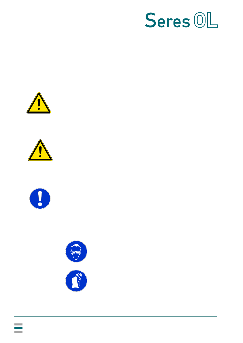
1.1. Warning Notices
The signal words and symbols used for safety-related notices have
the following meaning:
DANGER
Your life or physical wellbeing are in serious danger if such
warnings are ignored.
Follow the prevention instructions carefully.
WARNING
Severe injuries or damage to the equipment can occur if such
warnings are ignored.
Follow the prevention instructions carefully.
CAUTION
Damage to the equipment, minor injury, malfunctions or incorrect
process values can be the consequence if such warnings are
ignored.
Follow the prevention instructions carefully.
Mandatory
signs
The mandatory signs in this manual have the following meaning:
Safety goggles
Safety gloves

SOL-96.110.041 / 290621
TOPAZ Total Alkalinity
Safety Instructions
5
Warning signs The warning signs in this manual have the following meaning:
Electrical shock hazard
Corrosive
Harmful to health
Flammable
Hot surface
General warning

SOL-96.110.041 / 290621
TOPAZ Total Alkalinity
Safety Instructions
6
1.2. General Safety Regulations
Spare parts
and
disposables
Use only official Seres OL spare parts and consumables. If other
parts are used during the normal warranty period, the manufacturer’s
warranty is voided.
Modifications Modifications and instrument upgrades shall only be carried out by
an authorized service technician. Seres OL will not accept responsi-
bility for any claim resulting from unauthorized modification or alter-
ation.
Local
regulations
All wiring and connections (electrical, hydraulic) may only be carried
out by qualified personnel and in accordance with the local regula-
tions of the respective country.
WARNING
Electrical shock hazard
If proper operation is no longer possible, the instrument must
be disconnected from all power lines, and measures must be
taken to prevent inadvertent operation.
To prevent from electrical shock, always make sure that the
protective earth wire is connected.
Service shall be performed by authorized personnel only.
Whenever electronic service is required, disconnect the
instrument from power.
WARNING
Chemical exposure hazard
When handling chemicals or performing maintenance work
on hydraulic parts of the analyzer, wear suitable protective
equipment.
Read the Material Safety Datasheets (MSDS) of the chemicals
carefully.
WARNING
Do not use this instrument in presence of flammable liquids or
vapors as this may pose a safety hazard.
SOL-96.110.041 / 290621
TOPAZ Total Alkalinity
Safety Instructions
7
1.3. Handling Precautions
Position the box correctly (up/down). Carefully unpack the analyzer
and check it for visible damage. If the analyzer shows any visible
damage, do not connect it to power and contact customer service
immediately.
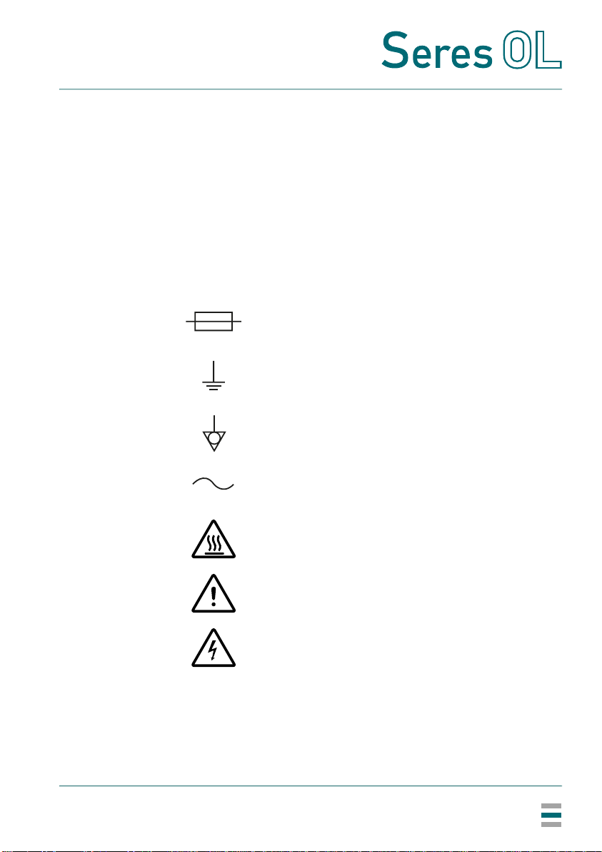
1.4. International Symbols Used
The symbols found on the instrument have the following meaning:
Electrical fuse
Ground
Equipotentiality
Alternating current
Hot surface
General attention
Electrical hazard

SOL-96.110.041 / 290621
TOPAZ Total Alkalinity
Product Description
8
2. Product Description
Application
range
The TOPAZ Total Alkalinity is a complete monitoring system for the
measurement of total alkalinity TA in potable water, demineralized
water production and process water.
Measuring
principle
Acid-base titration method:
The total alkalinity is titrated with sulfuric acid (concentration depend-
ing on measuring range) and a color indicator, the TAC indicator.
Configurations The instrument is available in the following configurations:
Three measuring ranges:
– 5 to 50 ppm CaCO3
– 10 to 200 ppm CaCO3
– 10 to 500 ppm CaCO3
Available with one, two, four or six measuring channels
(common measuring range)
Signal
outputs
Two signal outputs per measuring channel.
Current loop: 4–20 mA
Relays Five potential-free contacts per measuring channel with the following
functions:
two thresholds (high/high, low/high or low/low)
sample flow alarm
indication of the active measuring channel
maintenance indication
Maximum load: 1 A/24 V
Alarm relay One summary alarm for “analyzer failure”.
Maximum load: 1 A/24 V
Digital inputs One digital input per measuring channel to select the active sample
stream and one digital input to stop measurement.

SOL-96.110.041 / 290621
TOPAZ Total Alkalinity
Product Description
9
2.1. Instrument Specifications
Power supply Voltage:
Power consumption:
110–240 VAC
50/60 Hz
150 VA typical, 300 VA maximum
Environmental
conditions
Temperature:
Relative humidity:
Pollution level:
Installation category:
Maximum altitude:
5–40 °C
10% to 80%
2
II
2000 m
Do not use this instrument in presence of flammable liquids or gases.
Protect it from bad weather, humidity, corrosive substances and dust.
Process
connections
Sample inlet:
Sample outlet:
Sample outlet waste:
1/4” BSP F
soft tubing D INT 9 (single channel)
soft tubing D INT 19 (multi channel)
soft tubing D INT 12
Sample
requirements
Flow rate:
Temperature:
Inlet pressure:
Outlet pressure:
Particle size:
min. 30 l/h (opt. 40 l/h)
5–40 °C
0.1–2 bar
pressure-free
<20 µm
Air cleaning Inlet:
Required air flow:
6 mm tubing
50 l/h minimum of clean and dry air
Air cleaning can be used to protect the analyzer from a corrosive
environment.
Measuring
range
Range selection:
Limit of detection:
Repeatability:
Accuracy:
5–50 ppm CaCO3
≤5 ppm
≤±5% FS or ±5 ppm (whichever is greater)
≤±5% FS or ±5 ppm (whichever is greater)
Range selection:
Limit of detection:
Repeatability:
Accuracy:
10–200 ppm CaCO3
≤10 ppm
≤±5% FS or ±5 ppm (whichever is greater)
≤±5% FS or ±5 ppm (whichever is greater)
Range selection:
Limit of detection:
Repeatability:
Accuracy:
10–500 ppm CaCO3
≤10 ppm
≤±5% FS or ±5 ppm (whichever is greater)
≤±5% FS or ±5 ppm (whichever is greater)

SOL-96.110.041 / 290621
TOPAZ Total Alkalinity
Product Description
10
Wall cabinet Material:
Screws:
Weight:
Protection degree
Stainless steel SS316L
4x M6 (6x M6 with reagent shelf)
35 kg
IP55
Reagent shelf made of SS316L available as an option.
SOL-96.110.041 / 290621
TOPAZ Total Alkalinity
Product Description
11
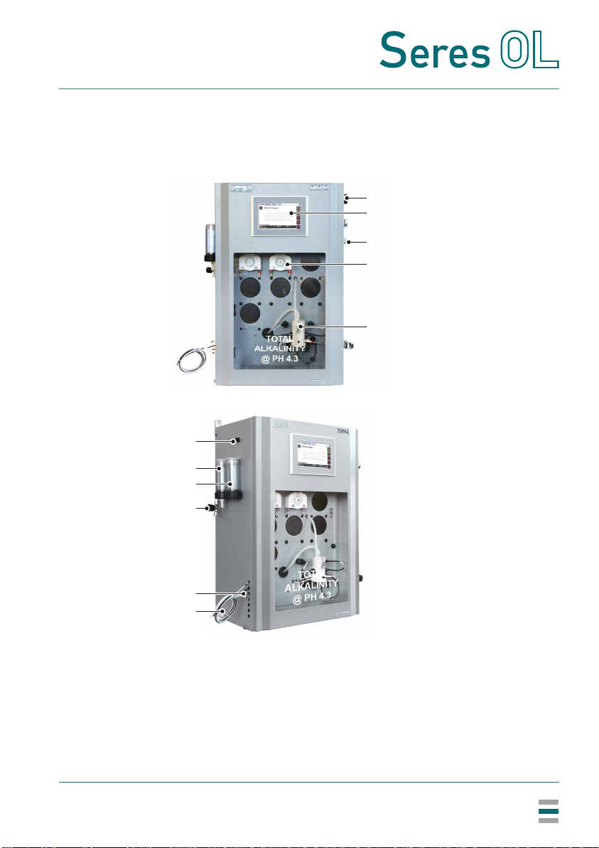
2.2. Instrument Overview
A
B
C
D
E
F
G
H
I
J
K
Power switch
Touchscreen
Cable glands
Peristaltic pumps
Photometer
Air cleaning inlet
Pressure reducing
device
Calibration vessel
Sample inlet tap
Reagent tubes
Drain
B
A
E
G
H
F
I
K
J
D
C

SOL-96.110.041 / 290621
TOPAZ Total Alkalinity
Installation
12
3. Installation
3.1. Before Installation
Unpacking Carefully unpack the analyzer and check it for visible damage.
On-site
requirements
Verify the electrical and hydraulic connections available at the
installation site against the requirements in Instrument Specifica-
tions, p. 9.
3.2. Mounting the Wall Cabinet
Mounting
requirements
Mount the instrument in vertical position. The display should be at
eye level to simplify operation and maintenance.
For dimensions see drawing on 10.
Reagent
bottles
Reagent bottles must be stored outside the analyzer. Provide a
suitable storage area near the analyzer.
As an option, a reagent shelf is available that can be installed directly
below the analyzer.
3.3. Hydraulic Connections
For hydraulic connections, refer to the separate hydraulic scheme.
SOL-96.110.041 / 290621
TOPAZ Total Alkalinity
Installation
13
3.4. Electrical Connections
WARNING
Risk of electrical shock
Always turn off power before manipulating electric parts. Only
operate the instrument from a power outlet which has a protec-
tive earth connection.
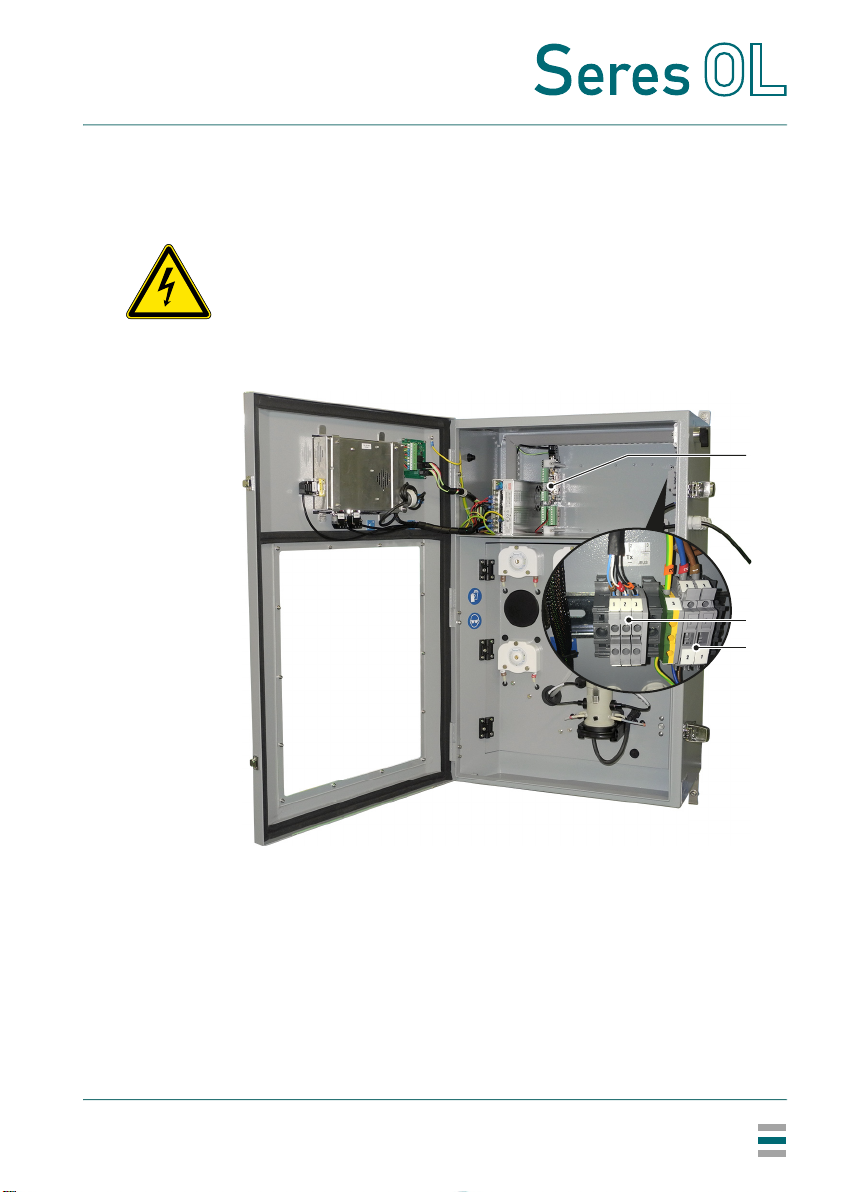
Overview of
electrical
connections
1) In multi-channel instruments, there is an I/O board for each measuring
channel. The I/O boards are arranged from left to right in ascending order
according to their channel number.
A
B
C
I/O board1) (relays, analog signal outputs, digital inputs)
RS485 interface
AC power
A
B
C
SOL-96.110.041 / 290621
TOPAZ Total Alkalinity
Installation
14
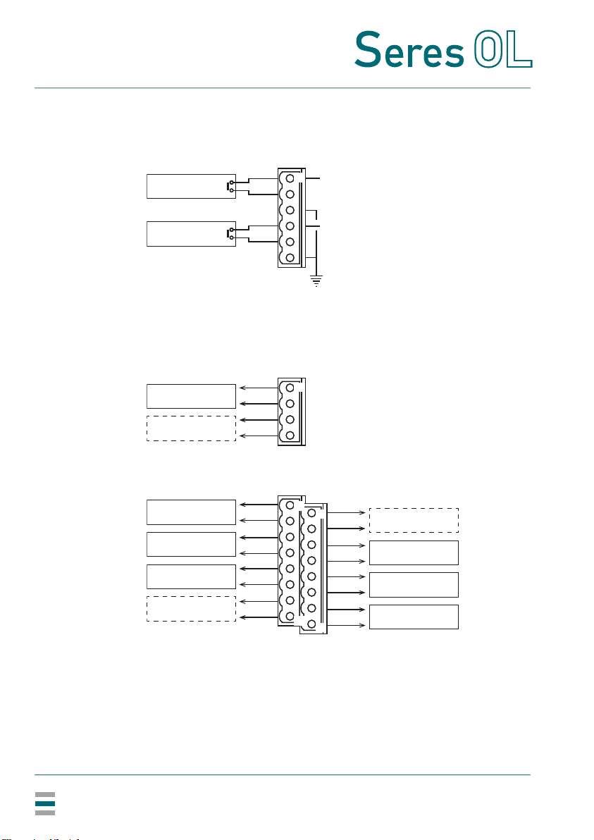
3.4.1 Connections on I/O Board
Connection
scheme
Note:
• Relays OUT_DIG1 and OUT_DIG8 are used to control internal
components of the analyzer. Do not connect anything else to
these contacts.
• Analog signal output OUT_ANA2 is reserved for customized
versions of the analyzer that provide a second value.
IN_DIG1
IN_DIG2
OUT_ANA1
OUT_DIG5
+24 V
J7
J9
J8
+24 V
+
-
OUT_ANA2
+
-
16
1
1
9
8
1
OUT_DIG6
OUT_DIG7
OUT_DIG8
OUT_DIG1
OUT_DIG2
OUT_DIG3
OUT_DIG4

SOL-96.110.041 / 290621
TOPAZ Total Alkalinity
Installation
15
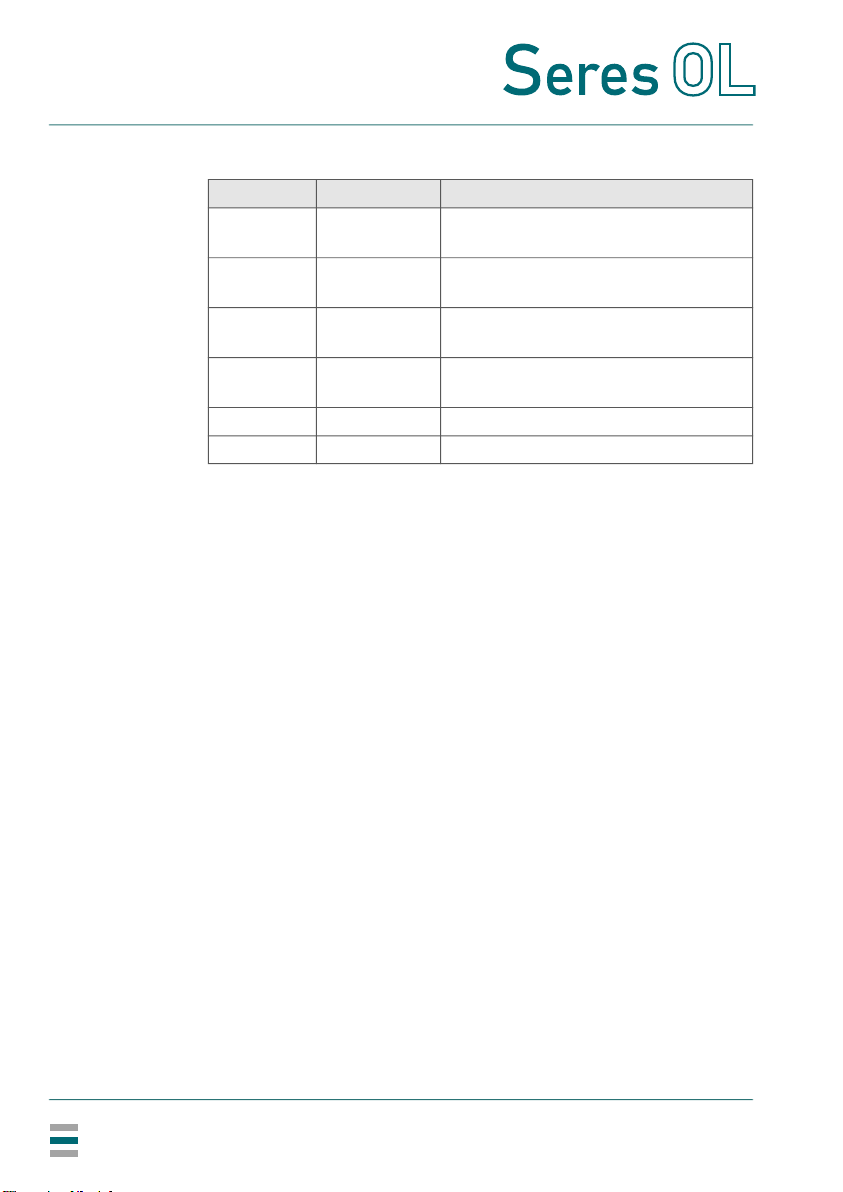
Digital inputs
Both digital inputs can be used with dry (potential-free) or wet
contacts (0/+24 V).
Note: It is strongly recommended to use dry contacts to avoid
electrical problems.
If dry contacts are used, connect them to terminals 1/2 and 4/5 of
connector J8 as shown in the connection scheme.
If control is provided by wet contacts, connect the reference to
pin 3 (6) and the selection voltage 0/+24 V to pin 2 (5) of connector
J8. Leave pins 1 and 4 unconnected.
Analog signal
outputs
(4–20 mA)
Name Available on Description
IN_DIG1 all measuring
channels
Activates or deactivates the measuring
channel.
Open contact:
Measuring channel will be measured
according to the programmed
channel sequence.
Closed contact:
Measuring channel will be skipped
and the user will be informed via a
message on the screen.
IN_DIG2 channel 1 Closing the contact will complete the
current measurement cycle and then
stop the measurement.
Name Available on Description
OUT_ANA1 all measuring
channels
Total alkalinity TA.
4 mA corresponds to low range
measurement and 20 mA to high
range measurement.
OUT_ANA2 all measuring
channels
Reserved.
SOL-96.110.041 / 290621
TOPAZ Total Alkalinity
Installation
16
Relays
Rating: 1 A / 24 V.
To configure thresholds 1 and 2, see Configuration of the Analyzer,
p. 42.
Name Available on Description
OUT_DIG2 all measuring
channels
Sample flow alarm
OUT_DIG3 all measuring
channels
Threshold 1
OUT_DIG4 all measuring
channels
Threshold 2
OUT_DIG5 all measuring
channels
Indication of the active sample stream
OUT_DIG6 channel 1 only Analyzer failure
OUT_DIG7 channel 1 only Maintenance
SOL-96.110.041 / 290621
TOPAZ Total Alkalinity
Installation
17
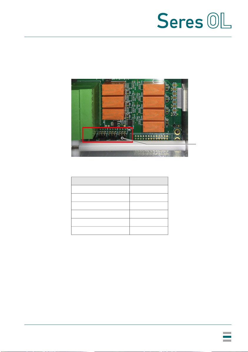
Setting
jumpers
Relays OUT_DIG2 to OUT_DIG7 can be configured as normally
open or normally closed by setting the corresponding jumpers on the
I/O board.
The default setting is normally open (jumper in the right position).
ALocation of jumpers on I/O board
Name of jumper Relay
JP8 OUT_DIG2
JP9 OUT_DIG3
JP10 OUT_DIG4
JP11 OUT_DIG5
JP12 OUT_DIG6
JP13 OUT_DIG7
A
SOL-96.110.041 / 290621
TOPAZ Total Alkalinity
Installation
18
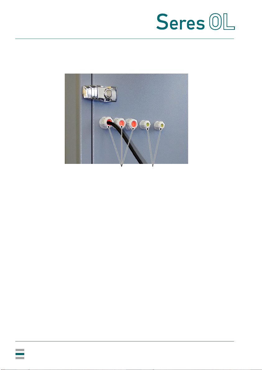
3.4.2 Cable thicknesses
In order to comply with IP55, use the following cable thicknesses:
Note: Seal cable glands that are not in use.
A
B
Outer diameter of cable: 7.5–13 mm
Outer diameter of cable: 4–8 mm
AB
Table of contents
Other Seres OL Measuring Instrument manuals


