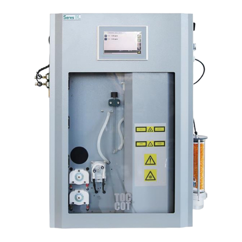
Seres OL TOC Evolution VUV User manual

TOC Evolution VUV
Operator’s Manual
TOC Evolution VUV
SOL-96.120.031 / 060223

© 2023, Seres OL SAS, France, all rights reserved.
The information contained in this document is subject to change without notice.
Customer Support
Seres OL and its representatives maintain a fully trained staff of technical specialists
around the world. For any technical question, contact your nearest Seres OL representa-
tive, or the manufacturer:
Seres OL SAS
ZA de la Sipière
219, Avenue de Provence
FR-13730 Saint-Victoret
France
Internet: www.seres-ol.com
E-mail: [email protected]
Document Status
Title: TOC Evolution VUV Operator’s Manual
ID: SOL-96.120.031
Revision Issue
00 February 2023 First edition

SOL-96.120.031 / 060223
TOC Evolution VUV
1
Table of Contents
1. Safety Instructions . . . . . . . . . . . . . . . . . . . . . . . . . . . . . . . . . . . . . . . . . . . . . 3
1.1. Warning Notices . . . . . . . . . . . . . . . . . . . . . . . . . . . . . . . . . . . . . . . . . . . . . . . . 4
1.2. General Safety Regulations . . . . . . . . . . . . . . . . . . . . . . . . . . . . . . . . . . . . . . . 6
1.3. Handling Precautions . . . . . . . . . . . . . . . . . . . . . . . . . . . . . . . . . . . . . . . . . . . . 7
1.4. International Symbols Used . . . . . . . . . . . . . . . . . . . . . . . . . . . . . . . . . . . . . . . 8
2. Product Description . . . . . . . . . . . . . . . . . . . . . . . . . . . . . . . . . . . . . . . . . . . . 9
2.1. Instrument Specifications . . . . . . . . . . . . . . . . . . . . . . . . . . . . . . . . . . . . . . . . . 11
2.2. Instrument Overview . . . . . . . . . . . . . . . . . . . . . . . . . . . . . . . . . . . . . . . . . . . . . 15
3. Installation . . . . . . . . . . . . . . . . . . . . . . . . . . . . . . . . . . . . . . . . . . . . . . . . . . . . 17
3.1. Before Installation . . . . . . . . . . . . . . . . . . . . . . . . . . . . . . . . . . . . . . . . . . . . . . . 17
3.2. Mounting the Wall Cabinet . . . . . . . . . . . . . . . . . . . . . . . . . . . . . . . . . . . . . . . . 17
3.3. Hydraulic Connections . . . . . . . . . . . . . . . . . . . . . . . . . . . . . . . . . . . . . . . . . . . 17
3.4. Electrical Connections. . . . . . . . . . . . . . . . . . . . . . . . . . . . . . . . . . . . . . . . . . . . 18
3.4.1 Connections on I/O Boards . . . . . . . . . . . . . . . . . . . . . . . . . . . . . . . . . . . . . . 19
3.4.2 Cable Thicknesses. . . . . . . . . . . . . . . . . . . . . . . . . . . . . . . . . . . . . . . . . . . . . 23
3.4.3 Cable Cross-Section . . . . . . . . . . . . . . . . . . . . . . . . . . . . . . . . . . . . . . . . . . . 23
3.4.4 AC Power. . . . . . . . . . . . . . . . . . . . . . . . . . . . . . . . . . . . . . . . . . . . . . . . . . . . 24
3.4.5 Jbus via RS485 (Option) . . . . . . . . . . . . . . . . . . . . . . . . . . . . . . . . . . . . . . . . 25
3.4.6 Jbus via TCP/IP (Option) . . . . . . . . . . . . . . . . . . . . . . . . . . . . . . . . . . . . . . . . 26
4. Startup . . . . . . . . . . . . . . . . . . . . . . . . . . . . . . . . . . . . . . . . . . . . . . . . . . . . . . . 27
4.1. Installing the Reagent Bottles . . . . . . . . . . . . . . . . . . . . . . . . . . . . . . . . . . . . . . 27
4.2. Filling the Liquid Seal . . . . . . . . . . . . . . . . . . . . . . . . . . . . . . . . . . . . . . . . . . . . 28
4.3. Starting Sample Flow . . . . . . . . . . . . . . . . . . . . . . . . . . . . . . . . . . . . . . . . . . . . 29
4.4. Preliminary Start-Up . . . . . . . . . . . . . . . . . . . . . . . . . . . . . . . . . . . . . . . . . . . . . 31
4.5. Run-in Period . . . . . . . . . . . . . . . . . . . . . . . . . . . . . . . . . . . . . . . . . . . . . . . . . . 33
4.6. Manual Measurement . . . . . . . . . . . . . . . . . . . . . . . . . . . . . . . . . . . . . . . . . . . . 33
4.7. Programming. . . . . . . . . . . . . . . . . . . . . . . . . . . . . . . . . . . . . . . . . . . . . . . . . . . 33
4.8. Jbus Table. . . . . . . . . . . . . . . . . . . . . . . . . . . . . . . . . . . . . . . . . . . . . . . . . . . . . 33
5. Operation . . . . . . . . . . . . . . . . . . . . . . . . . . . . . . . . . . . . . . . . . . . . . . . . . . . . . 34
5.1. Access Levels . . . . . . . . . . . . . . . . . . . . . . . . . . . . . . . . . . . . . . . . . . . . . . . . . . 34
5.2. User Interface . . . . . . . . . . . . . . . . . . . . . . . . . . . . . . . . . . . . . . . . . . . . . . . . . . 35
6. Maintenance. . . . . . . . . . . . . . . . . . . . . . . . . . . . . . . . . . . . . . . . . . . . . . . . . . . 36
6.1. Maintenance Schedule . . . . . . . . . . . . . . . . . . . . . . . . . . . . . . . . . . . . . . . . . . . 36
6.2. Stop of Operation for Maintenance . . . . . . . . . . . . . . . . . . . . . . . . . . . . . . . . . . 37
6.3. Replacing Reagents . . . . . . . . . . . . . . . . . . . . . . . . . . . . . . . . . . . . . . . . . . . . . 39
6.4. Replacing Peristaltic Pump Tubes . . . . . . . . . . . . . . . . . . . . . . . . . . . . . . . . . . 40
6.4.1 Reagent Pumps . . . . . . . . . . . . . . . . . . . . . . . . . . . . . . . . . . . . . . . . . . . . . . . 40

SOL-96.120.031 / 060223
TOC Evolution VUV
2
6.4.2 Sample Pump . . . . . . . . . . . . . . . . . . . . . . . . . . . . . . . . . . . . . . . . . . . . . . . . . 42
6.5. Replacing Soda Lime and Activated Charcoal. . . . . . . . . . . . . . . . . . . . . . . . . . 43
6.6. Replacing Silica Gel . . . . . . . . . . . . . . . . . . . . . . . . . . . . . . . . . . . . . . . . . . . . . . 45
6.7. Replacing UV Lamp . . . . . . . . . . . . . . . . . . . . . . . . . . . . . . . . . . . . . . . . . . . . . . 46
6.8. Manual Measurement and Calibration . . . . . . . . . . . . . . . . . . . . . . . . . . . . . . . . 47
6.8.1 Manual Measurement . . . . . . . . . . . . . . . . . . . . . . . . . . . . . . . . . . . . . . . . . . . 48
6.8.2 Zero Calibration . . . . . . . . . . . . . . . . . . . . . . . . . . . . . . . . . . . . . . . . . . . . . . . 48
6.8.3 Standard Calibration . . . . . . . . . . . . . . . . . . . . . . . . . . . . . . . . . . . . . . . . . . . . 49
6.9. Longer Stop of Operation. . . . . . . . . . . . . . . . . . . . . . . . . . . . . . . . . . . . . . . . . . 50
7. Configuration of the Analyzer. . . . . . . . . . . . . . . . . . . . . . . . . . . . . . . . . . . . . 51
8. Troubleshooting. . . . . . . . . . . . . . . . . . . . . . . . . . . . . . . . . . . . . . . . . . . . . . . . 55
8.1. What To Do If... . . . . . . . . . . . . . . . . . . . . . . . . . . . . . . . . . . . . . . . . . . . . . . . . . 55
8.2. Saving Diagnostic Data to USB Stick. . . . . . . . . . . . . . . . . . . . . . . . . . . . . . . . . 59
8.3. Replacing Parts . . . . . . . . . . . . . . . . . . . . . . . . . . . . . . . . . . . . . . . . . . . . . . . . . 60
8.3.1 NDIR . . . . . . . . . . . . . . . . . . . . . . . . . . . . . . . . . . . . . . . . . . . . . . . . . . . . . . . . 60
8.3.2 Glassware. . . . . . . . . . . . . . . . . . . . . . . . . . . . . . . . . . . . . . . . . . . . . . . . . . . . 61
8.3.3 Reagent Pump . . . . . . . . . . . . . . . . . . . . . . . . . . . . . . . . . . . . . . . . . . . . . . . . 68
9. Fluidic Diagrams . . . . . . . . . . . . . . . . . . . . . . . . . . . . . . . . . . . . . . . . . . . . . . . 70
10. Notes . . . . . . . . . . . . . . . . . . . . . . . . . . . . . . . . . . . . . . . . . . . . . . . . . . . . . . . . . 76

SOL-96.120.031 / 060223
TOC Evolution VUV
Safety Instructions
3
Operator’s Manual
This document describes the main steps for instrument setup,
operation and maintenance.
1. Safety Instructions
General The instructions included in this chapter explain the potential risks
associated with instrument operation and provide important safety
practices designed to minimize these risks.
If you carefully follow the information contained in this chapter, you
can protect yourself from hazards and create a safer work environ-
ment.
More safety instructions are given throughout this manual, at the
respective locations where observation is most important. Strictly
follow all safety instructions in this publication.
Target
audience
Operator: Qualified person who uses the equipment for its intended
purpose.
Instrument operation requires thorough knowledge of applications,
instrument functions and software as well as all applicable safety
rules and regulations.
OM location Keep the Operator’s Manual in proximity of the instrument.
Qualification,
training
To be qualified for instrument installation and operation, you must:
read and understand the instructions in this manual as well as
the Material Safety Data Sheets and
know the relevant safety rules and regulations.

SOL-96.120.031 / 060223
TOC Evolution VUV
Safety Instructions
4
1.1. Warning Notices
The signal words and symbols used for safety-related notices have
the following meaning:
DANGER
Your life or physical wellbeing are in serious danger if such
warnings are ignored.
Follow the prevention instructions carefully.
WARNING
Severe injuries or damage to the equipment can occur if such
warnings are ignored.
Follow the prevention instructions carefully.
CAUTION
Damage to the equipment, minor injury, malfunctions or incorrect
process values can be the consequence if such warnings are
ignored.
Follow the prevention instructions carefully.
Mandatory
signs
The mandatory signs in this manual have the following meaning:
Safety goggles
Safety gloves

SOL-96.120.031 / 060223
TOC Evolution VUV
Safety Instructions
5
Warning signs The warning signs in this manual have the following meaning:
Electrical shock hazard
Corrosive
Harmful to health
Flammable
Hot surface
UV radiation
General warning

SOL-96.120.031 / 060223
TOC Evolution VUV
Safety Instructions
6
1.2. General Safety Regulations
Spare parts
and
disposables
Use only official Seres OL spare parts and consumables. If other
parts are used during the normal warranty period, the manufacturer’s
warranty is voided.
Modifications Modifications and instrument upgrades shall only be carried out by
an authorized service technician. Seres OL will not accept responsi-
bility for any claim resulting from unauthorized modification or alter-
ation.
Local
regulations
All wiring and connections (electrical, hydraulic) may only be carried
out by qualified personnel and in accordance with the local regula-
tions of the respective country.
WARNING
Electrical shock hazard
If proper operation is no longer possible, the instrument must
be disconnected from all power lines, and measures must be
taken to prevent inadvertent operation.
To prevent from electrical shock, always make sure that the
protective earth wire is connected.
Service shall be performed by authorized personnel only.
Whenever electronic service is required, disconnect the
instrument from power.
WARNING
Chemical exposure hazard
When handling chemicals or performing maintenance work
on hydraulic parts of the analyzer, wear suitable protective
equipment.
Read the Material Safety Datasheets (MSDS) of the chemicals
carefully.

SOL-96.120.031 / 060223
TOC Evolution VUV
Safety Instructions
7
WARNING
Do not use this instrument in presence of flammable liquids or
vapors as this may pose a safety hazard.
WARNING
If it is necessary to carry out maintenance work with the UV lamp
switched on, wear UV protective goggles.
1.3. Handling Precautions
Position the box correctly (up/down). Carefully unpack the analyzer
and check it for visible damage. If the analyzer shows any visible
damage, do not connect it to power and contact customer service
immediately.

SOL-96.120.031 / 060223
TOC Evolution VUV
Safety Instructions
8
1.4. International Symbols Used
The symbols found on the instrument have the following meaning:
Electrical fuse
Ground
Equipotentiality
Alternating current
Hot surface
General attention
Electrical hazard
UV radiation

SOL-96.120.031 / 060223
TOC Evolution VUV
Product Description
9
2. Product Description
Application
range
The TOC Evolution VUV is a complete monitoring system for the
automatic, continuous measurement of total organic carbon (TOC) in
potable water and return condensate.
Measuring
principle
Advanced oxidation process with UV/VUV light and persulfate: By
purging the sample after adding acid, the inorganic carbon is con-
verted to CO2 and completely extracted from the sample. The sam-
ple is injected into the oxidation reactor. UV directly oxidizes the
organic matter which turns into CO2. The CO2 produced is then de-
tected by an NDIR (non-dispersive infrared) detector.
COD
correlation
Optionally, the measured TOC value can be correlated with the
chemical oxygen demand (COD). The COD is calculated using the
following equation:
COD = A * TOC + B
with A = COD correlation coefficient, B = COD offset.
The correlation has to be configured at the factory. Fill the equation
with the appropriate values for your sample and include them when
ordering the analyzer.
Note: The correlation is only valid if the customer's process
is stable and the customer is able to determine the correlation
equation.
Configurations The instrument is available in the following configurations:
Three measuring ranges:
– 0 to 2 ppm
– 0 to 10 ppm
– 0 to 100 ppm
available with one or two measuring channels (common
measuring range)
tangential filtration as an option (available with one measuring
channel only)
automatic calibration as an option

SOL-96.120.031 / 060223
TOC Evolution VUV
Product Description
10
Tangential
filtration
(option)
The sample is pumped through a tangentially positioned membrane
filter with a mesh size of 100 μm. Only a small amount, approximately
1%, is drawn through the membrane filter and used by the analyzer.
A sample flow of 500 l/h results in a velocity of 1.75 m/s. At the point
where the membrane filter is located, the cross-sectional area of the
sample line is reduced to double the sample velocity. The higher ve-
locity helps to keep the membrane filter clean.
In addition, the membrane filter is cleaned by compressed air back-
flushing at 2.5 bar (air supply with 7 bar provided by customer). The
frequency and duration are automatically controlled by the analyzer.
Input On request:
One input for dry (potential-free) contact to stop measurement at the
end of the measurement cycle.
Signal
outputs
Two signal outputs per measuring channel.
Current loop: 4–20 mA
A
B
Sample inlet
100 µm membrane filter
C
D
Filtered sample
Compressed air inlet
3.5 m/s
2.5 bar
0.5 l/h
500 l/h
1.75 m/s
A B DC

SOL-96.120.031 / 060223
TOC Evolution VUV
Product Description
11
Relays Three potential-free contacts per measuring channel with the follow-
ing functions:
two thresholds (high/low)
sample flow alarm
On request, one of the following functions can be configured ex-
works for relay 2 (replaces threshold 2):
“end of cycle indication” of the active sample stream for each
channel
maintenance/calibration indication
Maximum load: 1 A/24 V
Alarm relay One summary alarm for “analyzer failure”.
Maximum load: 1 A/24 V

SOL-96.120.031 / 060223
TOC Evolution VUV
Product Description
12
2.1. Instrument Specifications
Power supply Voltage:
Power consumption:
110 (configuration) or 230 VAC
50/60 Hz
300 VA maximum
Environmental
conditions
Temperature:
Relative humidity:
Pollution level:
Installation category:
Maximum altitude:
5–40 °C
5% to 95%
2
II
2000 m
Do not use this instrument in presence of flammable liquids or gases.
Protect it from bad weather, humidity, corrosive substances and dust.
Process
connections
Sample inlet:
Sample inlet with
tangential filtration:
Sample outlet:
Sample outlet (fast loop):
Sample outlet waste:
Sample outlet
(multi-channel):
1/4” BSP F
D 12 pipe
soft tubing D INT 9
soft tubing D INT 18
soft tubing D INT 12
soft tubing D INT 19
Sample
requirements
Flow rate:
Temperature:
Inlet pressure:
Outlet pressure:
Particle size:
min. 40 l/h (opt. 50 l/h)
5–50 °C
0.1–3 bar
pressure-free
<100 µm
Additional requirements for analyzer with tangential filter:
Flow rate:
Inlet pressure:
Air supply:
min. 200–500 l/h
0.5 to 1 bar
7 bar, clean and dry air
Cycle time 5 to 10 minutes, programmable interval

SOL-96.120.031 / 060223
TOC Evolution VUV
Product Description
13
FS = full scale
Measuring
range
Low-range variant:
Limit of detection:
Repeatability:
Accuracy:
0–2 ppm
0.01 ppm
±2% FS
±3% FS
Middle-range variant:
Limit of detection:
Repeatability:
Accuracy:
0–10 ppm
0.1 ppm
±2% FS
±3% FS
High-range variant:
Limit of detection:
Repeatability:
Accuracy:
0–100 ppm
0.5 ppm
±2.5% FS
±3% FS

SOL-96.120.031 / 060223
TOC Evolution VUV
Product Description
14
1-channel instrument with optional reagent shelf:
Wall cabinet Material:
Screws:
Weight:
Protection degree:
Stainless steel SS316
4x M8
80 kg
IP55
Reagent shelf made of SS316 available as an option.
551 mm / 21.69"
600 mm / 23.62"
780 mm / 30.71"
920 mm / 36.22"
993 mm / 39.09"
348 mm /
13.70"
422 mm /
16.61"
490 mm /
19.29"
273 mm /
10.75"
408 mm /
16.06"

SOL-96.120.031 / 060223
TOC Evolution VUV
Product Description
15
1-channel instrument with tangential filtration:
2-channel instrument:
920 mm / 36.22"
993 mm / 39.09"
422 mm /
16.61"
408 mm /
16.06"
551 mm / 21.69"
600 mm / 23.62"
913 mm / 35.94"
920 mm / 36.22"
993 mm / 39.09"
551 mm / 21.69"
600 mm / 23.62"
734 mm / 28.90"
422 mm /
16.61"
408 mm /
16.06"

SOL-96.120.031 / 060223
TOC Evolution VUV
Product Description
16
2.2. Instrument Overview
1-channel
instrument A
B
C
D
E
F
G
H
I
J
K
L
M
N
O
Power switch
Touchscreen
Cable glands
Fan
Activated charcoal
and soda lime
cartridges
Silica gel cartridge
Peristaltic pump
(sample)
Peristaltic pumps
(reagents)
Analyzed air outlet
Liquid seal
UV protective cover
Fast loop
Sample inlet tap
Air filter
Reagent tubes
H
G
A
B
C
D
E
F
J
I
K
O
N
L
M

SOL-96.120.031 / 060223
TOC Evolution VUV
Product Description
18
2-channel
instrument A
B
C
D
E
F
G
H
I
J
K
L
M
N
O
Power switch
Touchscreen
Cable glands
Fan
Activated charcoal
and soda lime
cartridges
Silica gel cartridge
Peristaltic pump
(sample)
Peristaltic pumps
(reagents)
Analyzed air outlet
Pressure reducing
device
Sample inlet taps
Liquid seal
UV protective cover
Air filter
Reagent tubes
J
K
I
L
M
O
N
H
G
A
B
C
D
E
F
Table of contents
Other Seres OL Measuring Instrument manuals
Popular Measuring Instrument manuals by other brands
CARLO GAVAZZI
CARLO GAVAZZI WM3-96 - PROGRAMMING instruction manual
COM-power corporation
COM-power corporation CLCE-400 instruction manual

Thermo Scientific
Thermo Scientific SPECTRONIC 200 user guide

Anaheim Scientific
Anaheim Scientific P771 user manual

Factair
Factair SAFEGUARD operating instructions
HEIDENHAIN
HEIDENHAIN MSE 1201 installation instructions

