Serial Cables PCI-SWGEN3-81U User manual

SERIAL CABLES PCI-SWGEN3-81U PCI Switch Board User’s Manual
Serial Cables
PCI-SWGEN3-81U
PCIe Switch Board User’s Manual
Revision 1.0
For the most up-to-date version of user manual, Please visit Serial Cables’ website at www.serialcables.com

SERIAL CABLES PCI-SWGEN3-81U PCI Switch Board User’s Manual
Change History
Ver Date of Release Description
V01 15th March 2018 Initial Release

SERIAL CABLES PCI-SWGEN3-81U PCI Switch Board User’s Manual
Table of contents
1. Introduction
1.1 Ov erview … ………… … ………… …… ………… …… …… …… …… ……… ……… ……………………… …… … P1
2. Hardware Description
2.1 Components Description………………………… ………………… …… ……………………..……………
P5
2.2
Connectors Pin Definit ion………
……… ……………………………… …………… ………………………
P6
2.3
Switch Mod e Selection…………………………………………… ……………………………..
……………
P9
3. CLI Manager
3.1 Start-up VT100 Screen………………………………………………………..…………………………… P11
3.2 CLI Command……………………………………………………………………………………….……………… P14
4. Firmware Upgrade………………………………………………………………….……………………….……………… P32

4
SERIAL CABLES PCI-SWGEN3-81U PCI Switch Board User’s Manual
1.
Introduction
1.1 Overview
SERIAL CABLES PCI-SWGEN3-81U NVMe switch board is designed to provide 12Bays NVMe
storage space expansion, The switch board equipped with two x16 SFF8644 for connecting host
or cascading.
The total maximum bandwidth is PCIe gen3 x32 512GT/s and allows up to 1-4 head-nodes
access the NVMe JBOF enclosure.
Downstream ports support twelve (12) SFF8643 connectors. It allows users to connect NVMe
SSD thru customized back plane board or SFF8643-SFF8639 cable adapter.
Switch board integrates Avago Technologies ExpressFabric Capella 2 PCIe Gen3 switch PEX9781,
implemented micro-controller provide users CLI commands for board and NVMe SSDs
management.

5
SERIAL CABLES PCI-SWGEN3-81U PCI Switch Board User’s Manual
1.
Hardware Description
2.1 Components Description
1. USB Port (Terminal)
2. Et hernet P ort
3. Quad Port MiniSAS HD SFF-8644
Connectors x2 pcs
4. FAN-Sink for PCIe Switch
5. Power connector
6. Connector for external FAN
7. Quad Port MiniSAS HD SFF-8643
Connectors x3 pcs
[SFF8643 Ports location definition]
6
SERIAL CABLES PCI-SWGEN3-81U PCI Switch Board User’s Manual
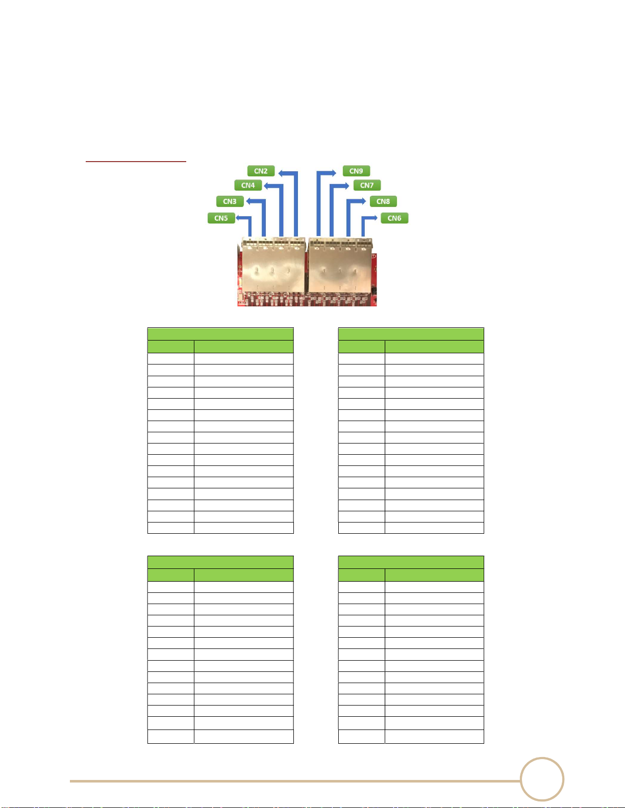
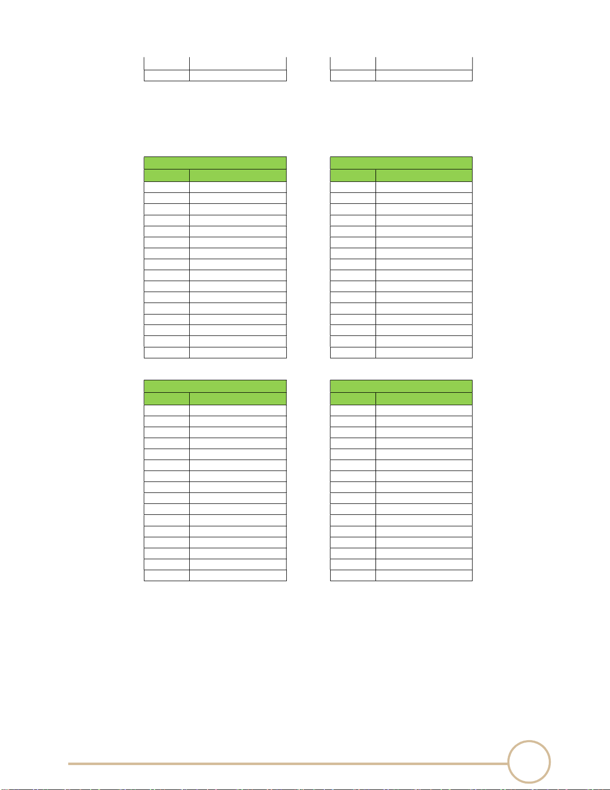
2.2 Connectors Pin Definition
SFF8644 connector
CN5
CN9
Pin No. Pin names Pin No. Pin names
A4 PEX_CONN_PERP28 A4 PEX_CONN_PERP60
A5 PEX_CONN_PERN28 A5 PEX_CONN_PERN60
A7 PEX_CONN_PERP29 A7 PEX_CONN_PERP61
A8 PEX_CONN_PERN29 A8 PEX_CONN_PERN61
B4 PEX_CONN_PERP30 B4 PEX_CONN_PERP62
B5 PEX_CONN_PERN30 B5 PEX_CONN_PERN62
B7 PEX_CONN_PERP31 B7 PEX_CONN_PERP63
B8 PEX_CONN_PERN31 B8 PEX_CONN_PERN63
C4 PEX_CONN_PETP28 C4 PEX_CONN_PETP60
C5 PEX_CONN_PETN28 C5 PEX_CONN_PETN60
C7 PEX_CONN_PETP29 C7 PEX_CONN_PETP61
C8 PEX_CONN_PETN29 C8 PEX_CONN_PETN61
D4 PEX_CONN_PETP30 D4 PEX_CONN_PETP62
D5 PEX_CONN_PETN30 D5 PEX_CONN_PETN62
D7 PEX_CONN_PETP31 D7 PEX_CONN_PETP63
D8 PEX_CONN_PETN31 D8 PEX_CONN_PETN63
CN3 CN7
Pin No. Pin names Pin No. Pin names
A4 PEX_CONN_PERP24 A4 PEX_CONN_PERP56
A5 PEX_CONN_PERN24 A5 PEX_CONN_PERN56
A7 PEX_CONN_PERP25 A7 PEX_CONN_PERP57
A8 PEX_CONN_PERN25 A8 PEX_CONN_PERN57
B4 PEX_CONN_PERP26 B4 PEX_CONN_PERP58
B5 PEX_CONN_PERN26 B5 PEX_CONN_PERN58
B7 PEX_CONN_PERP27 B7 PEX_CONN_PERP59
B8 PEX_CONN_PERN27 B8 PEX_CONN_PERN59
C4 PEX_CONN_PETP24 C4 PEX_CONN_PETP56
C5 PEX_CONN_PETN24 C5 PEX_CONN_PETN56
C7 PEX_CONN_PETP25 C7 PEX_CONN_PETP57
C8 PEX_CONN_PETN25 C8 PEX_CONN_PETN57
D4 PEX_CONN_PETP26 D4 PEX_CONN_PETP58
D5 PEX_CONN_PETN26 D5 PEX_CONN_PETN58
7
SERIAL CABLES PCI-SWGEN3-81U PCI Switch Board User’s Manual
D7 PEX_CONN_PETP27 D7 PEX_CONN_PETP59
D8 PEX_CONN_PETN27 D8 PEX_CONN_PETN59
CN4 CN8
Pin No. Pin names Pin No. Pin names
A4 PEX_CONN_PERP20 A4 PEX_CONN_PERP52
A5
PEX_CONN_PERN20
A5
PEX_CONN_PERN52
A7 PEX_CONN_PERP21 A7 PEX_CONN_PERP53
A8 PEX_CONN_PERN21 A8 PEX_CONN_PERN53
B4 PEX_CONN_PERP22 B4 PEX_CONN_PERP54
B5 PEX_CONN_PERN22 B5 PEX_CONN_PERN54
B7 PEX_CONN_PERP23 B7 PEX_CONN_PERP55
B8 PEX_CONN_PERN23 B8 PEX_CONN_PERN55
C4 PEX_CONN_PETP20 C4 PEX_CONN_PETP52
C5 PEX_CONN_PETN20 C5 PEX_CONN_PETN52
C7 PEX_CONN_PETP21 C7 PEX_CONN_PETP53
C8 PEX_CONN_PETN21 C8 PEX_CONN_PETN53
D4 PEX_CONN_PETP22 D4 PEX_CONN_PETP54
D5 PEX_CONN_PETN22 D5 PEX_CONN_PETN54
D7 PEX_CONN_PETP23 D7 PEX_CONN_PETP55
D8 PEX_CONN_PETN23 D8 PEX_CONN_PETN55
CN2 CN6
Pin No. Pin names Pin No. Pin names
A4 PEX_CONN_PERP16 A4 PEX_CONN_PERP48
A5 PEX_CONN_PERN16 A5 PEX_CONN_PERN48
A7 PEX_CONN_PERP17 A7 PEX_CONN_PERP49
A8 PEX_CONN_PERN17 A8 PEX_CONN_PERN49
B4 PEX_CONN_PERP18 B4 PEX_CONN_PERP50
B5 PEX_CONN_PERN18 B5 PEX_CONN_PERN50
B7 PEX_CONN_PERP19 B7 PEX_CONN_PERP51
B8 PEX_CONN_PERN19 B8 PEX_CONN_PERN51
C4 PEX_CONN_PETP16 C4 PEX_CONN_PETP48
C5 PEX_CONN_PETN16 C5 PEX_CONN_PETN48
C7 PEX_CONN_PETP17 C7 PEX_CONN_PETP49
C8 PEX_CONN_PETN17 C8 PEX_CONN_PETN49
D4 PEX_CONN_PETP18 D4 PEX_CONN_PETP50
D5 PEX_CONN_PETN18 D5 PEX_CONN_PETN50
D7 PEX_CONN_PETP19 D7 PEX_CONN_PETP51
D8 PEX_CONN_PETN19 D8 PEX_CONN_PETN51
8
SERIAL CABLES PCI-SWGEN3-81U PCI Switch Board User’s Manual
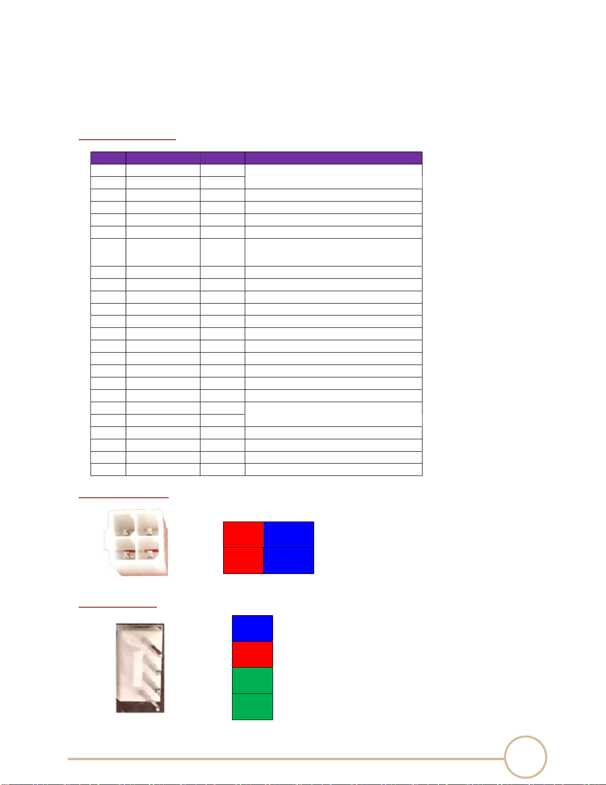
SFF8643 connector
Pin No.
Pin names Direction
Description
A1 SSD_CLK_0_N OUT HCSL type, non-SSC 100MHz
reference clock output
A2 SSD_CLK_0_P OUT
A4 PEX_GF_PERP3 IN
A5
PEX_GF_PERN3
IN
A7 PEX_GF_PERP2 IN
A8 PEX_GF_PERN2 IN
B1 PORT_GOOD#_0 OUT
1.
Assert
“
L
”
state when p
ort link up without any error.
2.
H or H to L translation represents physical error
detected or link in Gen1 or Gen2 speed.
B2 SSD_RESET#_0 OUT
R
e
set
output to device
B4 PEX_GF_PERP1 IN
B5 PEX_GF_PERN1 IN
B7 PEX_GF_PERP0 IN
B8 PEX_GF_PERN0 IN
C1 NC
C2 NC
C4 PEX_CONN_PETP3 OUT
C5 PEX_CONN_PETN3 OUT
C7 PEX_CONN_PETP2 OUT
C8 PEX_CONN_PETN2 OUT
D1 SSD_PRE0 IN
Present
“H” and IFDET “L” indicates an enterprise NVMe
SSD detected
D2 SSD_IFDET#0 IN
D4 PEX_CONN_PETP1 OUT
D5 PEX_CONN_PETN1 OUT
D7 PEX_CONN_PETP0 OUT
D8 PEX_CONN_PETN0 OUT
Power Connector
P12V GND
P12V GND
FAN Connector
GND
P12V
TACH
PWM

9
SERIAL CABLES PCI-SWGEN3-81U PCI Switch Board User’s Manual
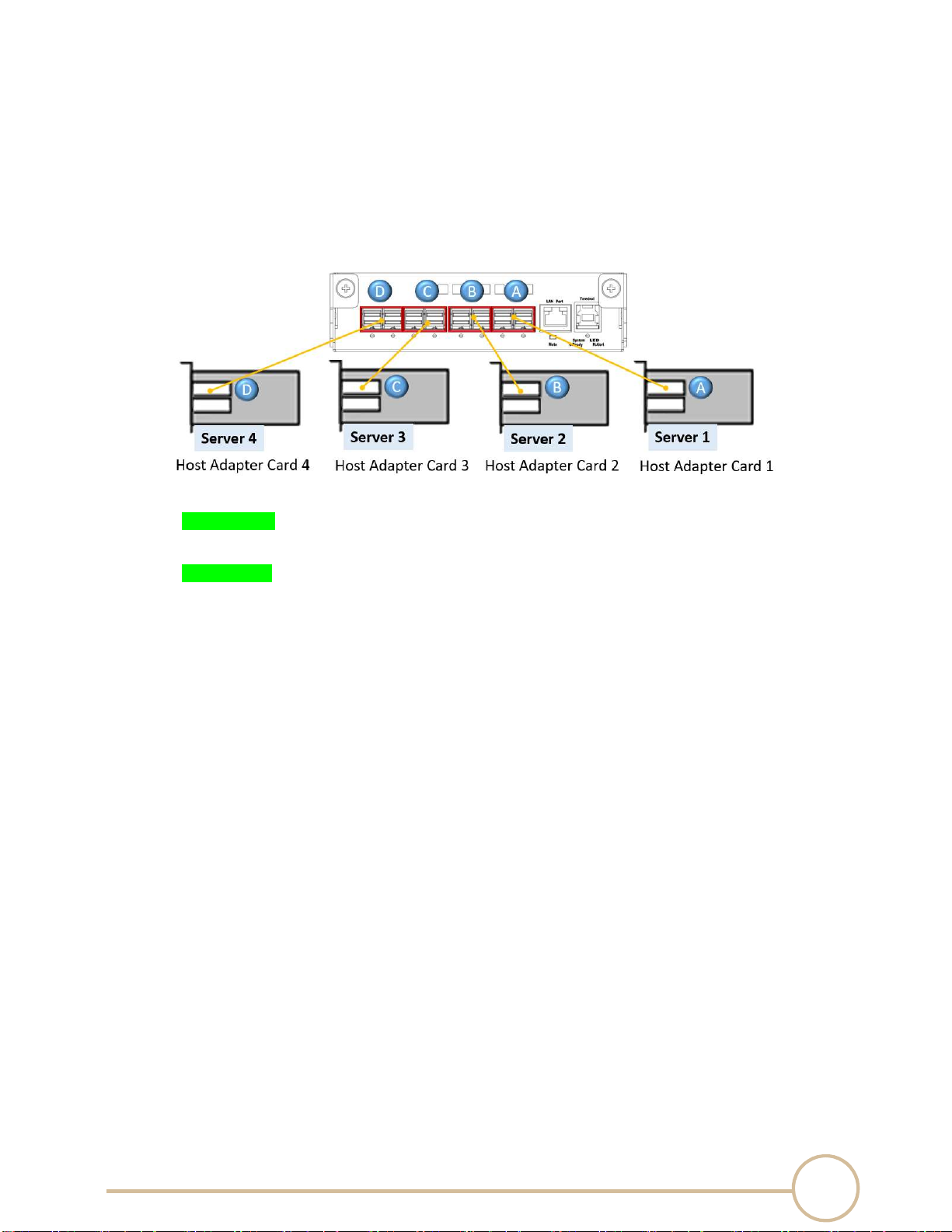
2.3 Switch Mode Selection
SERIAL CABLES PCI-SWGEN3-81U PCIe switch board features “mode selection” that allows
multiple host (up to 4)
connecting in switch board to access the NVMe SSD.
1. Mode 1: Base mode, x16 configuration.
Bandwidth:
PCIe switch board: PCIe Gen3 x16 128GT/s
NVMe SSD:
Server 1 can assess NVMe SSDs in SFF8643 Port 1 to 12.
2. Mode 2: Two VR mode, x16 configuration
Bandwidth:
PCIe switch board: PCIe Gen3 x32 256GT/s
NVMe SSD:
Server 1 can assess NVMe SSDs in SFF8643 Port 1 to 6.
Server 1 can assess NVMe SSDs in SFF8643 Port 7 to 12.
10
SERIAL CABLES PCI-SWGEN3-81U PCI Switch Board User’s Manual
3. Mode 3: Four VR mode, x8 configuration
Bandwidth:
PCIe switch board: PCIe Gen3 x32 256GT/s
NVMe SSD:
Server 1 can assess NVMe SSDs in SFF8643 Port 1 to 3.
Server 2 can assess NVMe SSDs in SFF8643 Port 4 to 6.
Server 3 can assess NVMe SSDs in SFF8643 Port 7 to 9.
Server 4 can assess NVMe SSDs in SFF8643 Port 10 to 12.

11
SERIAL CABLES PCI-SWGEN3-81U PCI Switch Board User’s Manual
CLI Manager
3.1 Start-uP VT100 Screen
PCIe switch board uses the USB port as the serial port interface. Please use the USB type
A male to Type B male cable to connect PCIe switch board to PC and operation system will
detect a new “
USB-to-Serial COM Port”. Please use this serial port
to configure the PCIe
switch b o ar d
.
Note: USB-to-Serial bridge chip is Prolific PL2303, user can download Windows, Mac OS X driver
from http://www.prolific.com.tw
By connecting a VT100 compatible terminal, or a PC operating in an equivalent terminal
emulation mode, all CLI administration functions can be exercised from the VT100 terminal.
There are a wide variety of Terminal Emulation packages, but for the most part they should be
very similar. The following setup procedure is an example setup VT100 Terminal in Windows 7
system using Tera Term 4.83 (a VT100 Terminal Emulation program and it’s an open-source,
free, software implemented, Terminal Emulator program).
Note: If you have encountered an issue with newer version of Tera Term, we recommend
you to use old version Tera Term. (4.83 or older version)

12
SERIAL CABLES PCI-SWGEN3-81U PCI Switch Board User’s Manual
Step 1. Install and launch Tera Term application (or Hyper Terminal requires version 3.0 or
higher).
Step 2: To ensure proper communications between PCIe switch board and the VT100 Terminal
emulation, please configure the VT100 Terminal emulation settings to the values shown below:
For “Port”, select COM3 in this example. (Depend on which COM port used on Host)
For “Baud rate”, select 115200.
For “Data”, select 8 bit. For “Parity”, select none.
For “Stop”, select 1 bit. For “Flow control”, select: none.
Click OK when you have finished your selections.
13
SERIAL CABLES PCI-SWGEN3-81U PCI Switch Board User’s Manual
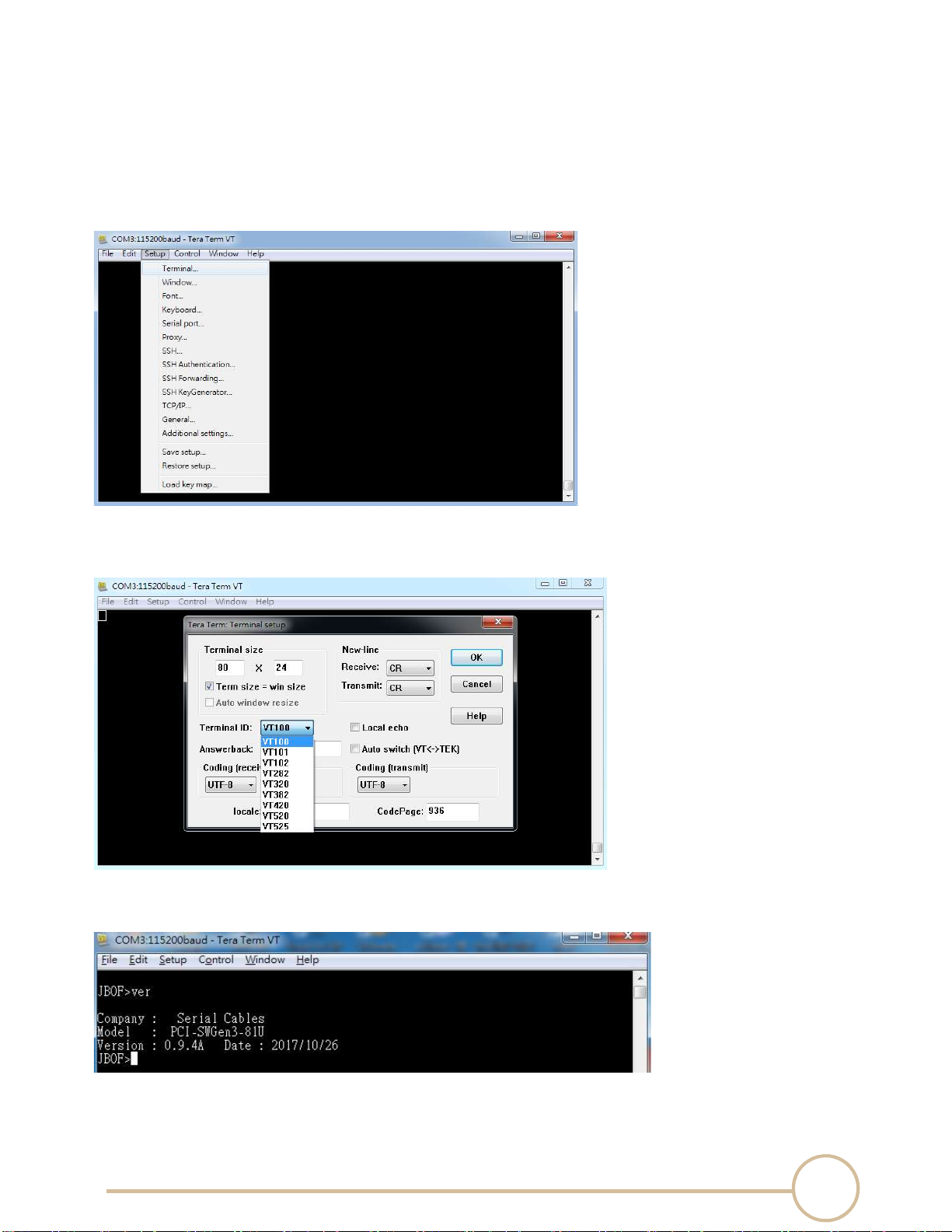
Step 3: Configure Terminal emulation type, please configure the VT100 Terminal emulation
settings to the values shown below:
For “Terminal ID”, select VT100.
Click OK when you have finished your selections.
Step 4: Setup is complete. Type “ver” [Enter] to check terminal, screen will print information
shown below:

14
SERIAL CABLES PCI-SWGEN3-81U PCI Switch Board User’s Manual
3.2 CLI Command
This section provides detailed information about PCIe switch board’s CLI function. Please type in
lower case for all of commands
• help Command
This command provides an on-line table of contents, providing brief descriptions of the supported
command groups and built-in commands.
Type “help” to get detail information about the CLI commands summary.
Syntax
Usage: help <group name>
Example:
JBOF>help
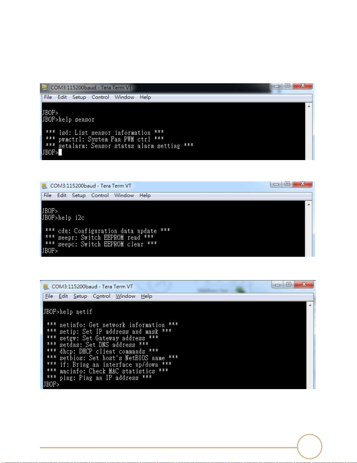
There are 4 command groups, if user want to check CLI commands in one of any groups.
JBOF>help nvme
15
SERIAL CABLES PCI-SWGEN3-81U PCI Switch Board User’s Manual
JBOF>help sensor
JBOF>help i2c
JBOF>help netif
16
SERIAL CABLES PCI-SWGEN3-81U PCI Switch Board User’s Manual
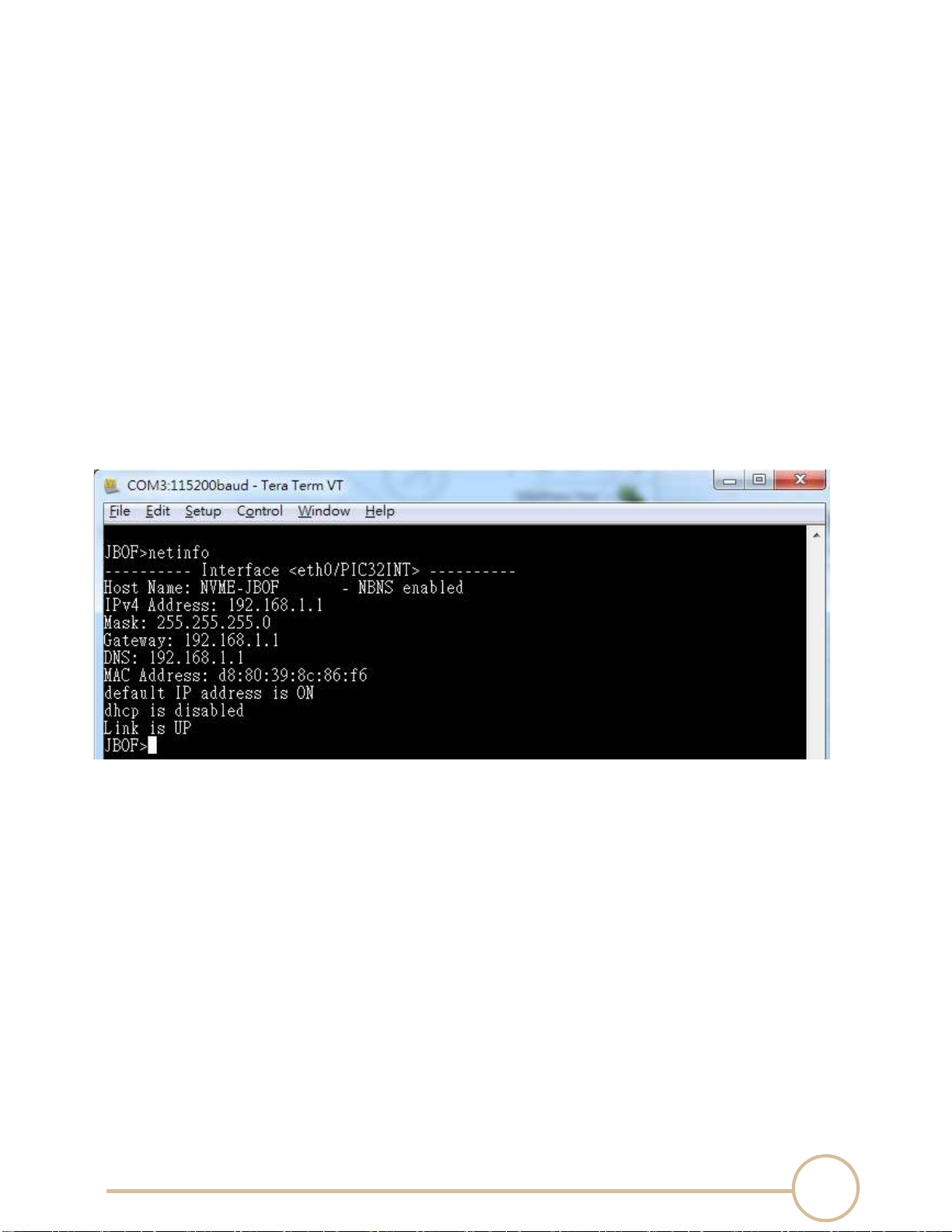
• netinfo Command
This command provides detail information of Ethernet interface.
Type “netinfo” to get detail information about the Ethernet interface.
Syntax
Usage: netinfo
Example: Check Ethernet interface information
JBOF>netinfo
NBNS – NetBIOS Name Service protocol
IPv4 Address – IP address of Interface
Mask – Netmask mask
Gateway – Default Gateway
DNS – IP address of DNS
MAC Address – A unique MAC address of Interface
default IP address On/Off
dhcp function enable/disable
Link status of Interface
17
SERIAL CABLES PCI-SWGEN3-81U PCI Switch Board User’s Manual
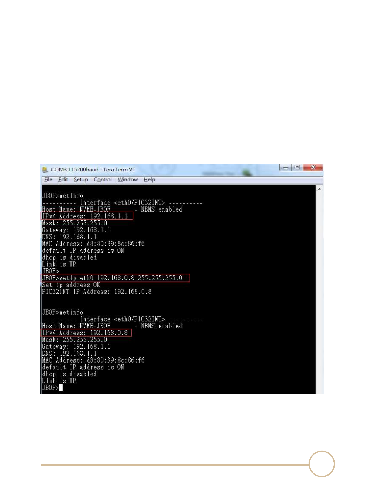
• setip Command
Set IP address and Subnetwork mask of Ethernet interface.
Syntax
Usage: setip <interface> <ipv4/6 address> <ipv4mask/ipv6 prefix len>
Example: Change Ethernet port IP address of interface eth0 to 192.168.0.8
JBOF>setip eth0 192.168.0.8 255.255.255.0

18
SERIAL CABLES PCI-SWGEN3-81U PCI Switch Board User’s Manual
• setgw Command
Set gateway IP address
Syntax
Usage: setgw <interface> <ipv4/6 address> <validTime>
Example: Change gateway IP address of interface eth0 to 192.168.0.1
JBOF>setgw eth0 192.168.0.1
19
SERIAL CABLES PCI-SWGEN3-81U PCI Switch Board User’s Manual
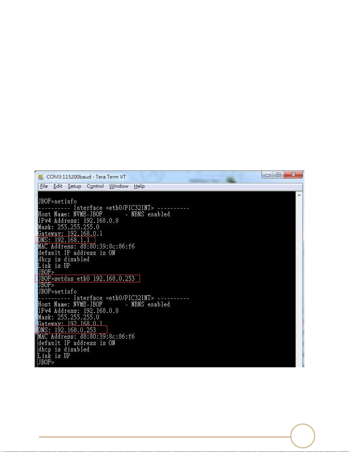
• setdns Command
Set DNS IP address.
Syntax
Usage: setdns <interface> <x.x.x.x>
Example: Change DNS server IP address of interface eth0 to 192.168.0.253
JBOF>setdns eth0 192.168.0.253
20
SERIAL CABLES PCI-SWGEN3-81U PCI Switch Board User’s Manual
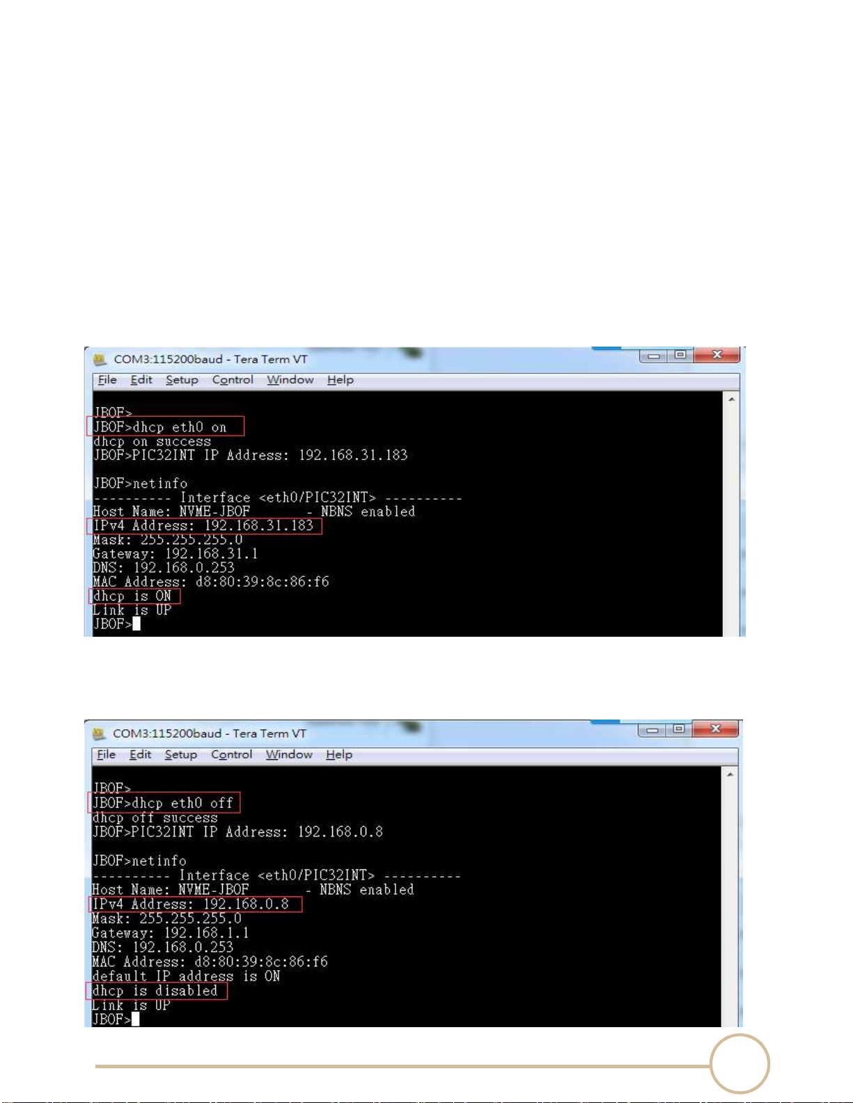
• dhcp Command
DHCP client command.
Syntax
Usage: dhcp <interface> <on/off/renew/request/info>
Example: Enable DHCP client function
JBOF>dhcp eth0 on
Example: Disable DHCP client function
JBOF>dhcp eth0 off
Table of contents
Other Serial Cables PCI Card manuals


 user guide")


