Visual Circuits 4ReelTime Pro User manual

ReelTime 4/
4ReelTime Pro
User Manual
Visual Circuits Corporation

Trademarks
The Visual Circuits logo is a registered trademark in the United States
and other countries. All other products, services or company names
mentioned herein are claimed as trademarks and trade names by their
respective companies.
c Visual Circuits, 1999-2000. All rights reserved.
No portion of this manual may be copied by any means without the prior
consent of Visual Circuits.
Visual Circuits
5155 East River Road, Suite 401
Minneapolis, MN 55421
http://www.visualcircuits.com
Visual Circuits Publication Number: 813-0001a

Federal Communications Radio Frequency Interference
Statement
WARNING: Changes or modifications to this unit not expressly
approved by the party responsible for compliance could void the user’s
authority to operate the equipment.
This equipment has been tested and found to comply with the limits for a
Class A digital device, pursuant to Part 15 of the FCC Rules. These
limits are designed to provide reasonable protection against harmful
interference when the equipment is operated in a commercial
environment. This equipment generates, uses, and can radiate radio
frequency energy and, if not installed and used in accordance with the
instructional manual, may cause harmful interference to radio
communications. Operation of this equipment in a residential area is
likely to cause harmful interference in which case the user will be
required to correct the interference at his own expense. However, if this
equipment does cause interference to radio or television equipment
reception, which can be determined by turning the equipment off and on,
the user is encouraged to try to correct the interference by one or more of
the following measures
❏Reorient or relocate the receiving antenna.
❏Increase the separation between equipment and receiver.
❏Connect the equipment to an outlet on a circuit different
from that to which the receiver is connected.
❏Consult the dealer or an experienced radio/television
technician for help.
Industry Canada
This Class A digital appartus meets all requirements of the Canadian
Interference-Causing Equipment Regulations.
Cet appareil numerique de la classe A respecte toutes les exigences du
Regulement sur le materiel brouilleur du Canada.

EMC and Safety Directive Compliance
The CE mark is affixed to this Visual Circuits Corporation product to
confirm compliance with the following European Community Directives:
Council Directive 89/336/EEC of 3 May 1989 on the approximation of
the laws of Member States relating to electromagnetic compatibility.
And
Council Directive 73/23/EEC of 19 February
1973 on the harmonization of the laws of
Member States relating to electrical equipment
designed for use within certain voltage limits:
Each ammended by
Council Directive 93/68/EEC of 22 July 1993
on the harmonization of CE marking
requirements.

i
CONTENTS
Overview 1
Introduction. . . . . . . . . . . . . . . . . . . . . . . . . . . . . . . . . .1
Genlock Options . . . . . . . . . . . . . . . . . . . . . . . . . . . . . .2
Audio/Video Distribution . . . . . . . . . . . . . . . . . . . . . . .3
ReelTime 4 vs. 4ReelTime Pro. . . . . . . . . . . . . . . . . . .4
API for Calling the Driver . . . . . . . . . . . . . . . . . . . . . .7
Installation Guide 9
Card Installation . . . . . . . . . . . . . . . . . . . . . . . . . .10
Cable Installation. . . . . . . . . . . . . . . . . . . . . . . . . .12
Jumper Configurations 15
Starting Playback . . . . . . . . . . . . . . . . . . . . . . . . . . . .16
Editing Driver Settings 17
Driver Editing Utility: VccReg.exe. . . . . . . . . . . . . . .17
Common Driver Parameters . . . . . . . . . . . . . . . . .17
Multi-Card Servers 29
Multi-Threading and Drive Mapping . . . . . . . . . . . . .29
Introduction . . . . . . . . . . . . . . . . . . . . . . . . . . . . . .29
Drive Mapping: Examples. . . . . . . . . . . . . . . . . . .30

ii
Contents
Troubleshooting Overview 33
Server Setup Check. . . . . . . . . . . . . . . . . . . . . . . . . . .33
Getting Started . . . . . . . . . . . . . . . . . . . . . . . . . . . . . .33
Troubleshooting Tips 37
BIOS Settings . . . . . . . . . . . . . . . . . . . . . . . . . . . .37
Blue screen . . . . . . . . . . . . . . . . . . . . . . . . . . . . . .37
Message says ’’VCC4PRO Driver not found!’’when
Vidserve is started . . . . . . . . . . . . . . . . . . . .37
No video or audio output. . . . . . . . . . . . . . . . . . . .38
Stuttering files during Playback . . . . . . . . . . . . . .38
"Latent Images" or "Flashing" during playback . .40
SMPTE time codes are not recognized properly. .41
On Screen (GIF) Overlay Information . . . . . . . . .42
Video blocks or stutters when starting playback. .43
Overall blocky or distorted playback . . . . . . . . . .43
Poor Onscreen Display (GIF) overlay. . . . . . . . . .43
Problems using the API. . . . . . . . . . . . . . . . . . . . .43
Mouse lags and overall poor system performance44
MPEG will not play on mapped network drive. . .44
Vidserve does not work at all . . . . . . . . . . . . . . . .44
Monitors roll / lose sync when files are loaded. . .44
All channels pause when a new file is started on a
channel . . . . . . . . . . . . . . . . . . . . . . . . . . . . .44
No audio . . . . . . . . . . . . . . . . . . . . . . . . . . . . . . . .45
More than one board will not play or make a few
horizontal lines on the screen. . . . . . . . . . . .45
RGB Sync or scan line noise. . . . . . . . . . . . . . . . .45

iii
Contents
Contacting Visual Circuits Corporation 47
Contacting Technical Support. . . . . . . . . . . . . . . . . . .47
What You Should Have Ready When You Call. . . . .47
What You Can Expect When You Call. . . . . . . . . . . .48
Technical Support Contact Information for the Value
Added Reseller (VAR) or Distributor Only . . . . .48
Returning Materials to Visual Circuits Corporation. .49
Appendix 51
Hardware Specifications . . . . . . . . . . . . . . . . . . . . . . .51
Audio Video Breakout Cables . . . . . . . . . . . . . . . . . .55
Theory of Operation . . . . . . . . . . . . . . . . . . . . . . . . . .58
How to Build a Server. . . . . . . . . . . . . . . . . . . . . . . . .61
Motherboard . . . . . . . . . . . . . . . . . . . . . . . . . . . . .61
Memory . . . . . . . . . . . . . . . . . . . . . . . . . . . . . . . . .61
Processor (CPU) . . . . . . . . . . . . . . . . . . . . . . . . . .61
Hard Disks. . . . . . . . . . . . . . . . . . . . . . . . . . . . . . .62
Chassis. . . . . . . . . . . . . . . . . . . . . . . . . . . . . . . . . .62
Tuning Multiple Board Servers. . . . . . . . . . . . . . .63

iv
Contents

1
OVERVIEW
Introduction
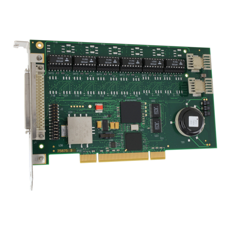
The Visual Circuits ReelTime 4 and the 4ReelTime Pro boards are
PCI bus boards that can play back up to four MPEG2 or MPEG1
video and audio files simultaneously. The ReelTime 4 supports
composite video, S-video, or interlaced RGBS video (Red, Green,
Blue, with combined H/V sync). This form of RGB video cannot
be displayed on a standard computer VGA monitor. There is CD
quality stereo audio output for each channel.
The 4ReelTime Pro supports composite video and optional S-video
output. The ReelTime 4 board has replaced the 4ReelTime Pro,
offering the same performance with increased functionality.
The ReelTime 4, in addition to adding RGB quality video output,
now provides software controlled volume adjustment on the
baseboard. (Volume control previously required an additional
audio or genlock card.) The ReelTime 4 supports the new RT
Daughter card for genlocking. The RT Daughter card also offers
an onboard blackburst generator. (See RT Daughter document for
details.)
Each board is designed to operate as a PCI bus master. This means
that once the software tells the board where to retrieve the MPEG
data from, the board will retrieve and route the data to the
appropriate channel with minimal CPU use. This feature allows
for multiple boards to run concurrently with smooth multi-channel
video and audio playback.
NOTE
ReelTime 4 and 4ReelTime Pro boards cannot
be mixed in the same server.

2
An On-Screen Display (OSD) is also included on the boards. This
OSD provides a full-resolution (up to 720x480) graphic or text
overlay on each MPEG file being played. The overlay can be set to
16 levels of transparency and can have up to 16 simultaneous
colors.
A Windows NT driver and software developer’s kit (SDK) is
included with the board. Consult with your Visual Circuits
representative for Linux and Windows 2000 support. Also check
for software downloads at www.visualcircuits.com.
Genlock Options
The RT Daughter card is an additional option for the ReelTime 4.
The connectors on the daughter card attach to the two rows of pins
on the RGB baseboard. The daughter card does not require an
additional PCI slot and easily supports multiple card servers. The
daughter board supports the ability to genlock to an external
composite video source. This module also includes a stereo audio
and composite video switch for roll-free switching between the
MPEG file being played and an external audio/video source. The
genlock module also adds volume and tone control to each audio
channel. An external composite video source can be "switched" to
and displayed on the video display monitors. Audio switching can
be done as well.

Overview
3
A "non-switching" version of Genlock is also available. This is
often used to provide a continuous signal sync for display devices.
The external sync source is often a blackburst generator. However,
any composite video signal source may be used. With "Non-
switching" Genlock, S-Video and RGB video output is supported.
The RT Daughter card also has its own on board blackburst
generator for continuous signal sync for video displays and
projectors if required.
Audio/Video Distribution
There are three options from Visual Circuits for audio/video
distribution. None of these devices are powered and follow all
standard audio/video cabling procedures.
1. Mini AV Breakout Box: This box brings out four BNC
composite video connectors, four S-video connectors and four
mini-phonejack stereo audio connectors. The box connects
directly to the DB-25 pin connector on the board and occupies
only one slot width on the back of a PC chassis. S-video and
composite videoare simultaneously available on each channel.
No RGB output is supported.
2. Rackmount Breakout Box: This brings out all video signals to
BNC connectors and audio to terminal post ("Phoenix type")
connectors. A twisted ribbon cable with adapters connects the
boards DB 25 pin to the rackmount’s 1 RU enclosure. The
Rackmount Breakout Box supports all configurations.
3. Universal Cable: This cable also supports all board
configurations and comes as a 19 inch cable which attaches to
each board’s DB 25. All output connectors are RCA female
type, requiring appropriate adapters and patch cables. (Visual
Circuits does not carry cable adapters and accessories.)

Overview
4
ReelTime 4 vs 4ReelTime Pro
The ReelTime 4 is the current multiple-channel board. The
software is compatible with the 4ReelTime Pro with the exception
of some initialization values and some additional driver parameter
selections.
Audio control is now selectable on the RGB baseboard through
software.
The ReelTime 4 supports Red, Green, Blue and Combined
Horizontal and Vertical Sync (H/V). The ReelTime 4 does not
support Sync on Green or Separate H/V Sync. The RGB output is
interlaced and cannot be viewed on standard PC monitors.
Each output channel of the ReelTime 4 can be individually
selected for Composite/S-video (available simultaneously) or RGB
(combined H/V Sync). This can be determined by selecting the
video output type. For more information see “VideoTypes”on
page 25.
CAUTION
Due to board revisions, idividual servers do
not support configurations of both 4ReelTime
Pro and ReelTime 4 boards integrated into the
same system

Overview
5
Figure 1 Front view of 4ReelTime Pro board.
Figure 2 Front view of ReelTime 4 board.

Overview
6
Figure 3 Back view of ReelTime 4 board.
The main visual difference between the ReelTime 4 and the
4ReelTime Pro boards are the four large LSI chips located on the
back side of the RGB board. When in doubt of which type of
board you are using look on the back side of the board as a
reference.

Overview
7
API for Calling the Driver
The source code for the Vidserve demo program is provided for
developers as an example of how to access the driver. The current
version of the driver uses a proprietary C API interface (instead of
a standard interface like MCI, ActiveMovie or Direct X).
Applications can use the driver by calling the dynamic link library
4REELAPI.DLL. The files needed (4REELAPI.LIB and
4REELAPI.H, 4REELSYN.H) are provided in the
VIDSERVE.ZIP file, along with the source code and MS VC++
2.0 project makefile for Vidserve. See 4REELAPI.H for a
complete description of the interface functions. The interchannel
synchronization functions are declared in 4REELSYN.H.
For further programming details see the ReelTime 4 SDK manual.

Overview
8

9
INSTALLATION GUIDE
The Visual Circuits Corporation 4ReelTime Pro and ReelTime 4
decoder boards are full sized PCI cards. The card is secured using
an IO mounting bracket secured to the chassis. This bracket is
affixed to the 25-pin female D Sub output of the board.
CAUTION
If a card is not lodged securely in the PCI slot
when the system power is applied, damage to
the 4ReelTime Pro or ReelTime 4 board may
occur
CAUTION
It is possible to damage system components,
primarily the system's mainboard, if power is
applied to an improperly seated card
CAUTION
Whenever installing a board, never force the
board into position. During the installation if
pressure or tension is noted, stop immediately
and refer to the chassis manufacturer's
specifications for card installation and
placement

Installation Guide
10
Card Installation
To install the card, carefully slide the board into the selected PCI
slot of the mainboard. Ensure that the bracket is aligned with the
IO opening of the chassis and that the outer edge of the card rests
securely according to the chassis’design. Consult with the chassis
manufacturer for specific guidelines.
Figure 4 Installation of board.
In some systems it may be necessary to install a mounting bracket
extension to the board in order to "reach" the card guide of the
chassis.
CAUTION
Follow all necessary precautions when
handling electrical circuit boards Damage can
occur due to frictional contact with board
circuitry or due to electrostatic discharge
(ESD)

Installation Guide
11
In some cases, the extension bracket may have to be modified to
accommodate the chip circuitry of the board before attaching to the
card.
The bracket mounting screws will be inserted from the back- side
of the card through the card holes. Be sure when attaching the
bracket not to damage any board circuitry.
Using extension brackets and nylon card guides prevents the board
from becoming dislodged from the PCI slot from shipping and
handling.
The use of brackets and card guides also prevents excessive board
"flexing" or "bouncing" due to shipping and handling. Excessive
vibrations and movement can crack or damage circuit board layers
and permanently damage the board.

Installation Guide
12
Cable Installation
1. Back the set-screws off fully before attaching the cable. Do not
use the attaching screws to “pull”the cable onto the female D
Sub connector of the board.
2. Orient the D Sub on the cable properly and apply slight even
pressure while connecting the D Subs.
3. Secure the Universal Cable in place with the two screws.
4. Attach the patch cables to the Universal Cable as per the
installation.
NOTE
Apply strain relief as re uired when attaching patch
cables. The set-screws will easily support the
Universal Cable strain, but will not take into account
the wieght and strain of any connected cables.
This manual suits for next models
1
Table of contents
Other Visual Circuits PCI Card manuals
