manuals.online logo
Brands
  1. Home
  2. •
  3. Brands
  4. •
  5. Contec
  6. •
  7. PCI Card
  8. •
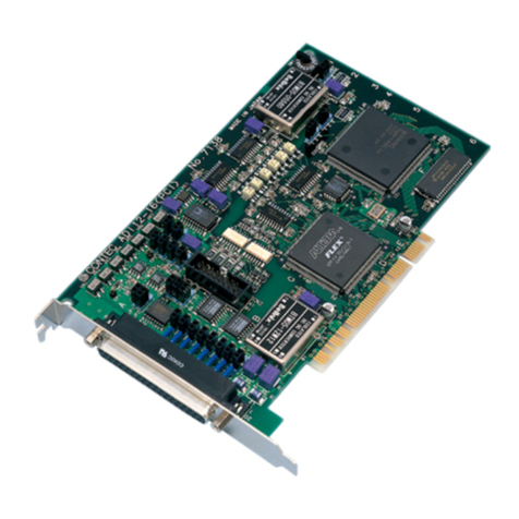
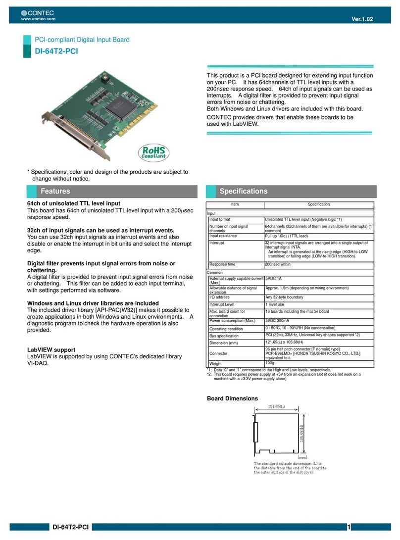
  9. Contec DA12-8PCI User manual

Contec DA12-8PCI User manual

Ver.2.13
DA12-8(PCI) 1
Digital to Analog Output Board for PCI
8ch type
DA12-8(PCI)
*Specifications, color and design of the products are subject to
change without notice.
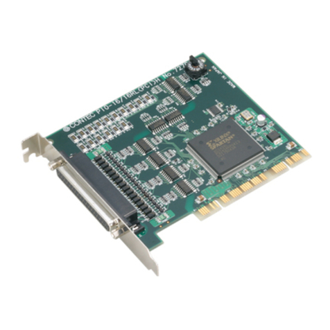
This product is a PCI bus-compliant interface boards that
performs digital-to-analog conversion.
This product performs D-A conversion using 8 output channels
at a conversion speed of 10 sec [100KSPS] and a resolution
of 12 bit.
Using the bundled driver library [API-PAC (W32)], you can
create Windows application software for this board in your
favorite programming language supporting Win32 API
functions, such as Visual Basic or Visual C++.
Support for unipolar and bipolar output ranges
An output range can be set for each channel by software.
Two output modes selectable
This product offers a choice of two output modes selectable.
One updates only the output voltage of a specified channel and
the other updates the output voltages of all channels.
Capable of updating the output voltage using a sampling
clock
This product can update the output voltage periodically using
the internal sampling clock or in synchronization with external
events using an external sampling clock.
Safety design to adjust output voltage to 0V when power
supply is turned on
To prevent the unstable voltage and the connected device of
D/A converter from fault and malfunctions when the power
supply is turned on, the circuit is designed to adjusts output
voltage of the analog output to 0V.
Optional units
Using optional units facilitates connections.
For more details on the option, please refer to “Cable &
Connector” or “Accessories (Option)”.
Item
DA12-8(PCI)
Analog Output
Isolated specification
Non-isolated
Number of output
channels
8channel
Output range
Bipolar 10V, 5V, Unipolar 0 - +10V
(Software setting by channel)
Absolute max. output
current
5mA
Output impedance
10or less
Resolution
12bit
Non-Linearity error *1
3LSB
Conversion speed *2
10sec [100KSPS] (Max.)
Sampling clock
Internal sampling clock : 10,000 - 1,073,741,824,000nsec
(Can be set in 250nsec units)
External sampling clock : TTL level falling edge
Output mode
Transparent output, synchronization output
Programmable timer
Setting frequency
500 - 1,073,741,824,000nsec (Can be set in 250nsec units)
Status
Count up, count up overrun
Timer output signal
TTL level 250nsec Low pulse, Low level output current IOL =
24mA
External trigger input
signal
Non-isolated input 1 channel (TTL level falling edge)
Status
Trigger input, trigger input overrun
I/O address
32 ports boundary
Interrupt level
1 point
Operating condition
0 - 50C, 10 - 90RH (No condensation)
Power consumption (Max.)
+5VDC 800mA
Bus specification
32bit, 33MHz, Universal key shapes supported *3 *4
Connector
37pin D-SUB connector [F (female) type]
DCLC-J37SAF-20L9 [mfd.by JAE] or equivalence to it
Dimension (mm)
176.41(L) x 105.68(H) *5
Weight
135g
Certification
CE,VCCI
*1 A linearity error approximately 0.1of full-range may occur when operated at 0C or
50C ambient temperature.
*2 The minimum clock speed actually available depends on the OS and driver.
*3 This product requires +5V power supply from the expansion slot (it does not work in a
+3.3V environment).
*4 DA12-8(PCI): If the board No. is 7184, PCI bus specification is 32bit, 33MHz, 5V.
*5 Boards with different board numbers are different in these specifications. See Table 6.4
"Different in the specification" at the end of this document.
Specification
Features
Ver.2.13
DA12-8(PCI) 2
Board Dimensions
[mm]
176.41(L)
105.38(H)
The standard outside dimension (L) is
the distance from the end of the board
to the outer surface of the slot cover.
Windows version of analog I/O driver
API-AIO(WDM)/API-AIO(98/PC)
[Stored on the bundled Disk driver libraryAPI-PAC(W32)]
These drivers are the Windows version driver library software
that provides products in the form of Win32 API functions (DLL).
Various sample programs such as Visual Basic and Visual C++,
etc and diagnostic program useful for checking operation is
provided.
For more details on the supported OS, applicable language
and how to download the updated version, please visit the
CONTEC’s Web site (http://www.contec.com/apipac/).
Linux version of analog I/O driver API-AIO(LNX)
[Stored on the bundled Disk driver libraryAPI-PAC(W32)]
The API-AIO(LNX) is the Linux version driver software which
provides device drivers (modules) by shared library and kernel
version. Various sample programs of gcc are provided.
available after installation.)
For more details on the supported OS, applicable language
and how to download the updated version, please visit the
CONTEC’s Web site (http://www.contec.com/apipac/).
Data acquisition VI library for LabVIEW VI-DAQ
(Available for downloading (free of charge) from the
CONTEC web site.)
This is a VI library to use in National Instruments LabVIEW.
VI-DAQ is created with a function form similar to that of
LabVIEW's Data Acquisition VI, allowing you to use various
devices without complicated settings.
See http://www.contec.com/vidaq/ for details and download of
VI-DAQ.
Cable (Option)
Flat Cable with 37-Pin D-SUB Connector at One End
: PCA37P-1.5 (1.5m)
Shield Cable with 37-Pin D-SUB Connector at One End
: PCA37PS-0.5P (0.5m)
: PCA37PS-1.5P (1.5m)
Flat Cable with 37-Pin D-SUB Connectors at either Ends
: PCB37P-1.5 (1.5m)
Shielded Cable with Two 37-pin D-SUB Connectors
: PCB37PS-0.5P (0.5m)
: PCB37PS-1.5P (1.5m)
Coaxial Cable for Single-ended Inputs (16 channels)
: PCC16PS-1.5 (1.5m)
: PCC16PS-3 (3m)
Connector (Option)
37-pin D-SUB (Male) Connector Set (5 Pieces)
: CN5-D37M
Accessories (Option)
General Purpose Terminal (M3 x 37P) :DTP-3A *1
Screw Terminal (M2.6 x 37P) : DTP-4A *1
Termination panel with BNC connectors
for Analog Multi-function Boards : ATP-16 *1
Screw Terminal Unit (M3 x 37P) : EPD-37A *1*2
Screw Terminal Unit (M3.5 x 37P) : EPD-37 *1
*1 PCB37P-* or PCB37PS-* optional cable is required separately.
*2 "Spring-up" type terminal is used to prevent terminal screws from falling off.
* Check the CONTEC’s Web site for more information on these options.
Board [DA12-8(PCI)] …1
First step guide … 1
Disk *1 [API-PAC(W32)] …1
Serial number label…1
Product Registration Card & Warranty Certificate…1
*1 The Disk contains the driver software and User’s Guide.
Connector shape
To connect an external device to this product, plug the cable
from the device into the interface connector (CN1) shown
below.
CN1
37
20
19
1
- Connector used
A 37pin D-SUB connector[F(female)type]
DCLC-J37SAF-20L9 [mfd.by JAE]equivalent
- Applicable connector
17JE-23370-02(D8C) [mfd by DDK, M(male)type]
Interface connector(CN1)
* Please refer to page 2 for more information on the supported cable and accessories.
Examples of Connecting Options
DA12-16(PCI)
DA12-8(PCI)
DA12-4(PCI)
PCC16PS *2
PCA37P-1.5
Option
Cable
PCA37PS *3
PCB37P-1.5
Option
Cable
PCB37PS *1
The accessory with this mark can
be mounted on a DIN rail by using
DIN-ADP1.
*1 : PCB37PS-0.5P/1.5P is
recommended.
*2 : PCC16PS-1.5/3 is
recommended.
*3 : PCA37PS-0.5P/1.5P is
recommended.
Relay terminal stand
Screw Terminal Unit
EPD-37A, EPD-37
General Purpose Terminal
DTP-3A
*1-m shielded cable bundled
Screw Terminal
DTP-4A
*1-m shielded cable bundled
Termination panel with BNC connectors
for Analog Multi-function Boards
ATP-16
Support Software
Cable & Connector
Accessories
Packing List
How to connect the connectors
Support Software
Support Software
Cable & Connector
Ver.2.13
DA12-8(PCI) 3
Connector Pin Assignment
CN1
19
18
17
16
15
14
13
12
11
10
9
8
7
6
5
4
3
2
1
Settling Busy Output
Digital Ground
Analog Ground
Analog Ground
Analog Ground
Analog Ground
Analog Ground
Analog Ground
Analog Ground
Analog Ground
Analog Ground
Analog Ground
Analog Ground
Analog Ground
Analog Ground
Analog Ground
Analog Ground
Analog Ground
37
36
35
34
33
32
31
30
29
28
27
26
25
24
23
22
21
20
Timer Output
External Trigger Input
External Sampling Clock Input
N.C.
Analog Output 7
N.C.
Analog Output 6
N.C.
Analog Output 5
N.C.
Analog Output 4
N.C.
Analog Output 3
N.C.
Analog Output 2
N.C.
Analog Output 1
N.C.
Analog Output 0
Analog Output 0 to Analog
Output 7
Analog output signal. The numbers correspond to channel
numbers.
Analog Ground
Common analog ground for analog output signals.
External Trigger Input
External trigger input signal.
External Sampling Clock
Input
External sampling clock input signal.
Timer Output
Programmable timer output signal.
Settling Busy Output
Output signal indicating the settling time until the analog output
reaches a predetermined voltage after output data is set.
Digital Ground
Comm Digital ground common to the signals other than the
analog output signal, including the external sampling clock
input signal.
N.C.
No connection to this pin.
CAUTION
Do not connect any of the outputs and power outputs to the
analog or digital ground.
Neither connect outputs to each other. Doing either can
result in a fault.
The sections below describe how to connect the signals using
flat cable and shielded cable.
The following figure shows an example of optional flat cable
(PCA37P) connection.
Connect the CN1 analog output channels and ground to the
external device's input and ground.
Connecting the Analog Output (Flat Cable)
Analog Output
Analog Ground
BOARD CN1 Cable Target
Digital Multi-Meter etc.
The following example connects a signal source to this product
using a shielded cable such as a coaxial cable (PCC16PS)
available as an option.
Use shielded cable if the distance between this product and
external device is long or if you want to provide better
protection from noise.
Use the core of the shielded cable to connect the analog output
of CN1 to the input of the external device and use the shield
braid to connect the CN1's analog ground to the external
device's ground.
Connecting the Analog Output (Shield Cable)
Analog Ground
Shield cable
Analog Output
BOARD CN1 Target
Digital Multi-Meter etc.
CAUTION
If this product and the target receive noise or the distance
between this product and the signal source is too long,
data may not be input properly.
The maximum output current-carrying capacity of the
analog output signal is ±5 mA. Check the specifications
of the target before connecting this product to it.
Do not connect any of the outputs and power outputs to the
analog or digital ground.
Do not connect the analog output signal to the other analog
output signal and output signal of external device. Doing
so may malfunction.
Do not plug or unplug the interface connector to or from
while the PC or external device power is turned on. Doing
so may malfunction.
The DA converter may cause glitches as it contains no
deglitcher.
The analog output signal may temporarily vary in output
voltage when the power is turned on or when the range is
switched. If this variation in output voltage is a problem,
insert, for example, a relay between this product and the
external device.
This section shows how to connect the control signal(“External
Trigger Input”, “Settling Busy Output” and so on) by using a flat
cable.
All the control signals are TTL level signals.
Connecting the Input Signal
Digital Ground
BOARD CN2 Cable Target
External Trigger
Input
External Sampling
Clock Input
10k
Connecting the Output Signal
Digital Ground
BOARD CN2 Cable Target
Timer Output
Settling Busy Output
IOL=24mA
CAUTION
Do not short the output signals to analog ground, digital
ground, and/or power line. Doing so may damage this
product.
Do not connect the each output signal to the other output
signal and output signal of external device. Doing so may
malfunction.
Analog Outputs
External Sampling Clock Input
External Trigger Input
Settling Busy Output
Timer Output
FPGA
DC/DC
converter
PCI bus
CN1
DAC DACDAC DAC DAC TTL
buffer
DA12-8(PCI) : DAC x 2
DA12-4(PCI) : DAC x 1
Block Diagram
Block Diagram
Connecting the Analog Output Signal
Connecting the Control signal
Ver.2.13
DA12-8(PCI) 4
The DA12-8(PCI) is different in specifications, depending on
the board number as listed below.
■DA12-8(PCI)
Board No.
No.7184
No.7184A
No.7184B
Dimension (mm)
176.41(L)×106.68(H)
176.41(L)×106.68(H)
176.41(L)×105.68(H)
Different in the specification

This manual suits for next models

1

Other Contec PCI Card manuals

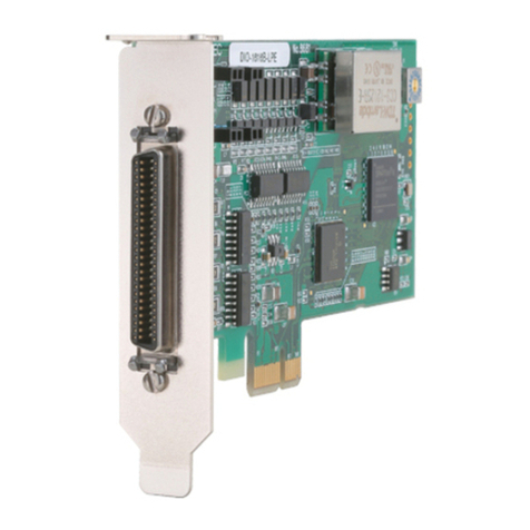
Contec COM-2PD-LPE User manual

Contec

Contec COM-2PD-LPE User manual

Contec IPC SERIES User manual

Contec

Contec IPC SERIES User manual

Contec FX-DS540-MPCI6 User manual

Contec

Contec FX-DS540-MPCI6 User manual

Contec IPC SERIES User manual

Contec

Contec IPC SERIES User manual

Contec CNT24-4 User manual

Contec

Contec CNT24-4 User manual

Contec AO-1616L-LPE User manual

Contec

Contec AO-1616L-LPE User manual

Contec AO-1604CI3-PCI User manual

Contec

Contec AO-1604CI3-PCI User manual

Contec DIO-1616T-LPE User manual

Contec

Contec DIO-1616T-LPE User manual

Contec DIO-0808L-PCI User manual

Contec

Contec DIO-0808L-PCI User manual

Contec DS540-MPCI4WAP User manual

Contec

Contec DS540-MPCI4WAP User manual

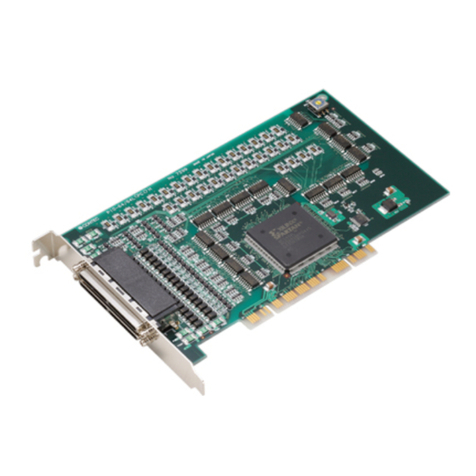
Contec PIO-64/64L(PCI)H User manual

Contec

Contec PIO-64/64L(PCI)H User manual

Contec DIO-32DM2-PE User manual

Contec

Contec DIO-32DM2-PE User manual

Contec DIO-1616T-PE User manual

Contec

Contec DIO-1616T-PE User manual

Contec CNT24-4D(PCI)H User manual

Contec

Contec CNT24-4D(PCI)H User manual

Contec SMC-8DL-PCI User manual

Contec

Contec SMC-8DL-PCI User manual

Contec GPIB-F-LPE User manual

Contec

Contec GPIB-F-LPE User manual

Contec FX-DS540-MPCI6 User manual

Contec

Contec FX-DS540-MPCI6 User manual

Contec DIO-96D-LPE User manual

Contec

Contec DIO-96D-LPE User manual

Contec AI-1216B-RB1-PCI User manual

Contec

Contec AI-1216B-RB1-PCI User manual

Contec AD16-64(LPCI)LA User manual

Contec

Contec AD16-64(LPCI)LA User manual

Contec FX-DS540-MPCI4W User manual

Contec

Contec FX-DS540-MPCI4W User manual

Contec DIO-48D-LPE User manual

Contec

Contec DIO-48D-LPE User manual

Contec CNT24-4(PCI) User manual

Contec

Contec CNT24-4(PCI) User manual

Contec ADI12-16(PCI) User manual

Contec

Contec ADI12-16(PCI) User manual

Popular PCI Card manuals by other brands

Kvaser PCIEcan 2xHS v2 user guide

Kvaser

Kvaser PCIEcan 2xHS v2 user guide

HMS IXXAT INpact Slave PCIe user manual

HMS

HMS IXXAT INpact Slave PCIe user manual

SpinCore Technologies RadioProcessor USB Operation manual

SpinCore Technologies

SpinCore Technologies RadioProcessor USB Operation manual

Abocom WCM5202 Specification sheet

Abocom

Abocom WCM5202 Specification sheet

Assmann Digitus DS-30224 manual

Assmann

Assmann Digitus DS-30224 manual

hilscher CIFX 50-XX user manual

hilscher

hilscher CIFX 50-XX user manual

CSL 303506 user manual

CSL

CSL 303506 user manual

SIIG CyberPro PCI 1S Quick installation guide

SIIG

SIIG CyberPro PCI 1S Quick installation guide

Farallon NetLINE USB user guide

Farallon

Farallon NetLINE USB user guide

Renesas Tsi301 HyperTransport user manual

Renesas

Renesas Tsi301 HyperTransport user manual

Loopcomm LP-7665 user manual

Loopcomm

Loopcomm LP-7665 user manual

Lindy PCI 1S (16C950 128 FIFO) user manual

Lindy

Lindy PCI 1S (16C950 128 FIFO) user manual

IBM 3600 quick start guide

IBM

IBM 3600 quick start guide

National Instruments IMAQ PCI-1426 user manual

National Instruments

National Instruments IMAQ PCI-1426 user manual

JYTEK PCIe-69529 user manual

JYTEK

JYTEK PCIe-69529 user manual

Linksys WMP54GS EU user guide

Linksys

Linksys WMP54GS EU user guide

Avermedia EZMaker SDK Quick installation guide

Avermedia

Avermedia EZMaker SDK Quick installation guide

D-Link DWL-510 owner's manual

D-Link

D-Link DWL-510 owner's manual

manuals.online logo
manuals.online logoBrands
  • About & Mission
  • Contact us
  • Privacy Policy
  • Terms and Conditions

Copyright 2025 Manuals.Online. All Rights Reserved.