SERO DC AWA-SS-7 User manual
-Please read this operating manual before using the Heap Pump-
INSTALLATION AND MAINTENANCE INSTRUCTIONS
AIXIA
DC INVERTER AIR SOURCE HEAT PUMP - ALL IN ONE -
MODEL:
DC AWA-SS-7 / DC AWA-SS-9
DC AWA-SS-12 / DC AWA-SS-15
(230V/50Hz)


Contents
1
System description
Principle of operation ............................................ 3
Control panel
Layout .................................................................. 5
Explanation .......................................................... 5
General information for the installer
Transport and storage ............................................ 7
Installation .............................................................. 7
Copper pipe connecting ........................................ 7
Inspection of the installation .................................. 7
Pipe connections
General .................................................................. 8
Copper Pipe connections ...................................... 8
Pipe connection (heating medium) ........................ 9
Pipe connections (water heater) ............................ 9
Pump capacity diagrams, heating medium side .. 12
Electrical connections
Wiring of the terminal (mode one) ......................... 15
Connecting the room temperature sensor ........... 16
1.5mm2 terminal connection ............................. 17
2.5mm2 terminal connection ............................... 17
Commissioning and adjusting
Preparations ........................................................ 20
Filling and venting the heating medium system ... 20
Readjusting, heat medium side ............................ 21
Emptying the water heater .................................. 21
Control
General Information ............................................. 22
Menus .................................................................. 22
Main Menu Information ........................................ 23
Sub-menu Operation............................................. 24
Sub-menu Heat Curve .......................................... 25
Sub-menu Temperature ....................................... 26
Sub-menu Time Setting ........................................ 28
Adjustments to be made regularly ........................ 36
Heat Generation-General....................................... 36
Adjustment of the CURVE valve ........................... 36
Adjustment of ROOM valve.................................... 37
Adjustment of Part of the Heat Curve .................... 39
Adjustment the MIN and MAX valve ..................... 40
Maximum Return Line Temperature ..................... 42
Warm water Production........................................... 42
Regular checks .......................................................43
Check of the Operating Mode ............................... 43
Dealing with malfunctions
Draining, heat medium side ................................ 53
Component placement
Component positions 1 ........................................ 54
Component positions 2......................................... 55
Component positions 3 ....................................... 56
List of components
List of components ................................................ 57
Dimensions
Dimensions and setting-out coordinates .............. 58
Accessories
Accessories .......................................................... 61
Technical specifications
Technical specifications ....................................... 62
Unit Description .................................................... 3
Principle of heatpump ........................................... 4
Functions ............................................................. 6
Symbols ............................................................... 6
How to adjust the rate of flow .............................. 13
Connect the power cord ....................................... 14
Wiring of the terminal (mode two) ......................... 15
Connecting the outside temperature sensor ........ 16
Wiring diagram ( Indoor Unit ) .............................. 18
Graph of recent change in TEMPERATURE..........41
Checking the Water Level of the Heating system .43
Checking the safety valves .................................... 43
In the event of leakage .......................................... 43
Alarm Messages .................................................... 44
Terminology and Abbreviations ............................. 51
Draining, water tank.............................................. 53
Draining, the chassis............................................. 53
Inspection ............................................................. 21
Adjust the heat medium pump .............................. 21
Enclosed kit .......................................................... 61
Sub-menu Integral ................................................. 26
Sub-menu Reset ................................................... 35
Sub-menu Man Test .............................................. 35
Dimensions of the DC AWA-SS-7 outdoor unit .... 59
Dimensions of the DC AWA-SS-9 outdoor unit .... 59
Dimensions of the DC AWA-SS-12 outdoor unit... 60
Dimensions of the DC AWA-SS-15 outdoor unit... 60
Description of the switch board ............................. 52
How to connect the copper pipes ......................... 10
The step and diagram of collect refrigerant .......... 11
Sub-menu DEFROST ............................................ 31
Degree Minute's(DM) instruction............................ 27
Sub-menu SETTING ............................................. 33
Sub-menu LANGUANG.......................................... 35
Adjustment of the HIGH T STOP and
LOW T STOP value
............................................. 40
Connecting the defrost temperature sensor ......... 16
Wiring diagram ( Outdoor Unit ) ........................... 19
Sub-menu Operating Time .................................... 34
DC AWA-SS seriesconsistsofaheatpump,waterheater,
electrical module, circulation pumps and a control sys-
tem. DC AWA-SS series is connected to the Outdoor Unit
and heating medium circuits.
Theheatsource of theDC AWA-SS seriesis providedfrom
air. the Outdoor Unit of the system is a heat exchanger
for collecting the heat of air.
The air emits its heat to the refrigerant in the evapo-
rate of Outdoorunit. It then vaporises and is com-
pressed in the compressor. The refrigerant, the tem-
perature of which has now been raised, is passed to
the condenser where it gives off its energy to the heat-
ing medium circuit and, if necessary, to the water
heater. After the condenser there is a built-in electrical
module which cuts in if there is a high demand.
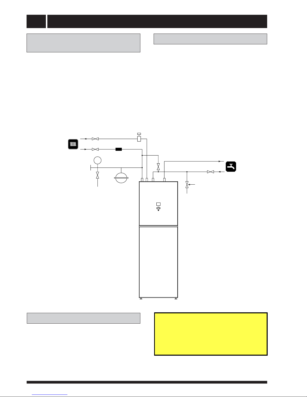
System description 2
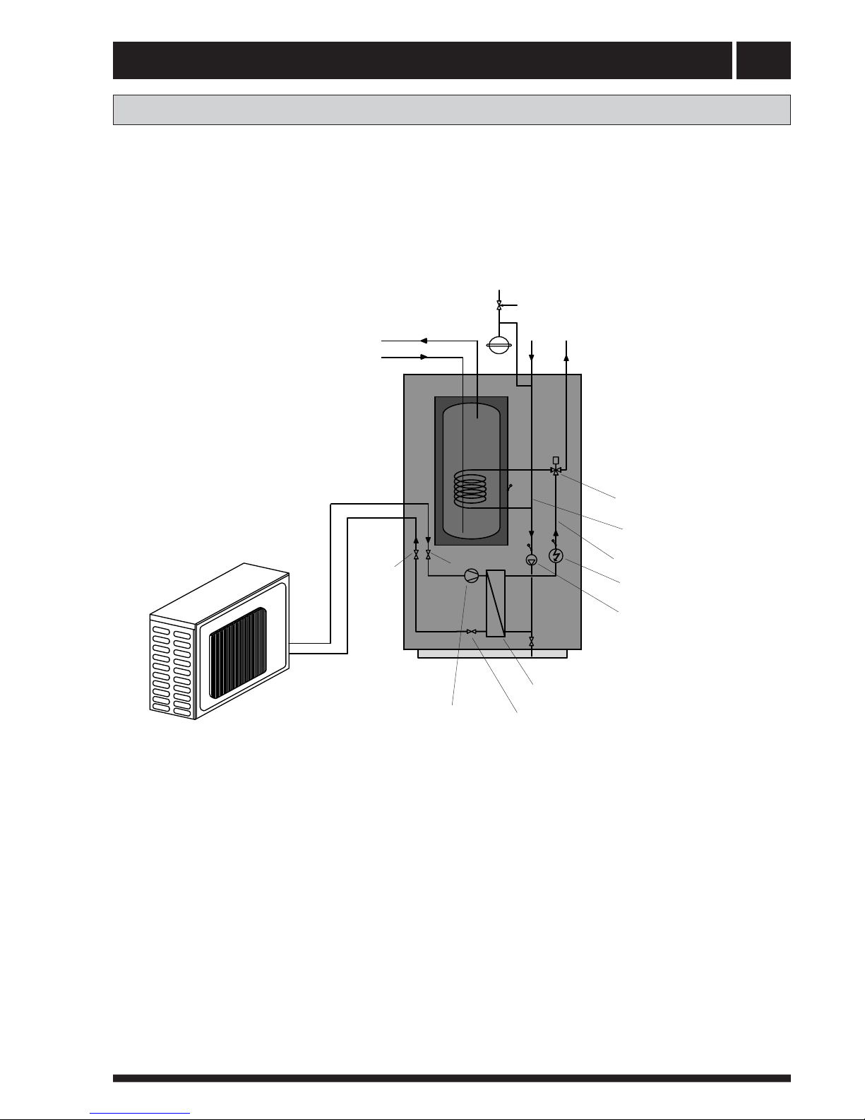
Principle of operation
CW
HW
Expansion
vessel Heating
flow
Heating
return
The heating medium side and
the hot water side must be fit-
ted with the necessary safety
equipment in accordance with
the applicable regulations.
Condenser
Compressor Expansion
valve
Heating
medium
pump
Heating medium return
Heating medium flow
Three-way valve
Electrical
auxiliary heater
(VB),
(VB),
Gas valve
Liquid
valve
Outdoor unit

System description
3
Unit Description
In order to get the best results from the climate system DC AWA-SS series you should read through the
section For the System manager in these Installation and Maintenance instructions.
DC AWA-SS series
is
a
climate system
for
heating
houses
and
apartment
buildings
as
well
as
industrial
properties.
Air
is
used
as
the
heat
exchange
source.
DC AWA-SS series
is
a
complete
heating
installation
for
heating
and
hot
water
.
It
is
fitted
with
new design
on
the
market
to
be
developed
specifically
for
heat
pumps.
A
new
evaporator
enables
a
new
and
impr
oved
cir
culation
system
for
the
r
efrigerant.
The
heat
pump
has
an
integrated
150 or 200 litr
e
water
tank
and
an
immer
sion
heater
.
The
T
ap
W
ater
Stratification
system
impr
oves
the
ef
ficiency
of
heat
transfer
by
keeping
the
water
in
distinct
thermal
layers
in
the
water
tank.
The unit
is
fitted
with
a
r
egulating
computer
,
which
is
contr
olled
over
a
graphic
display
unit.
Heat
is
distributed
thr
oughout
the
house
over
a
hydr
onic
heating
system
r
eferr
ed
to
as
low temperatur
e
system
with
a
maximal
water
temperatur
e
to
radiators
(feed water
temperatur
e)
of
65°C.
Most
of
the
heating
demand
is
taken
car
e
of
by
the
heat
pump
(compressor
unit),
the
auxiliary
heater
being
star
ted
only
when
demands
exceed
available
heat
pump
capacity
.
DC AWA-SS series
consists
of
five
main
components:
a.
Heat
Pump
Unit
Rotory or Scr
oll-compr
essor
Stainless
steel
heat
exchangers
Cir
culation
pumps
for
heating
systems
V
alves
and
safety
equipment
for
r
efrigerant
system,
complete
with
necessary
electric
components
b.
W
ater
Heater
150 or 200
litr
e
Lined
with
copper
sheet
against
corr
osion
or
made
of
stainless
steel
Maintenance
fr
ee
as
no
anode
is
used
c.
Reversing
V
alve
Opening
or
closing
the
connection
to
water
heater
accor
ding
to
operating mode:
heating
or
warm
water
pr
oduction
d.
Auxiliary
Heater
3/6/9
kW
electric
heating
element
Three-step
capacity
contr
ol
Fitted
on
feed water
line
Delivers
back-up
heat
in
case
of
gr
eat
heat
demand
that
exceeds
heat
pump
capacity
Star
ts
automatically
,
pr
ovided
operating
mode
“AUTO”
has
been
selected
e.
Regulating
Equipment
The
r
egulating
system
contr
ols
heat
pump
components
(compressor
,
cir
culation
pumps,
auxiliary
heater
and
r
eversing
valve).
Based
on
data
r
eceived
fr
om sensors,
it
star
ts
or
stops
heat
pump
operation
and
determines
whether
he
a
ting
or
warm
water
shall
be
pr
oduced.
The
system
consists
of:
Control
computer
with
graphic
display
unit
T
emperatur
e
sensors
(outside
air
,room,
feed
line,
r
eturn
line
system)
System description 4
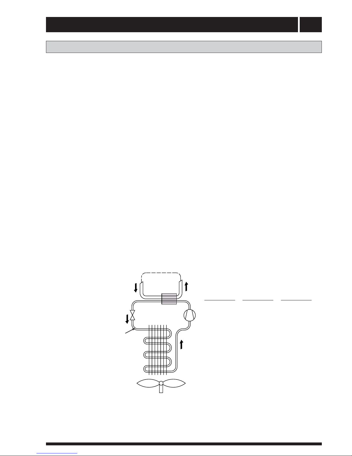
Principle of heat pump
A
heat
pump
can
exploit the
ener
gy
contained
in
natural heat
sour
ces.
Or
,
to
put
it
dif
fer
ently
,
the
heat
pump
”collects”
heat
ener
gy
fr
om
the
heat
sour
ce.
This
makes
the
heat
pump
a
very
environmentally
friendly
and
economically
sound
alternative
for
space
heating.
a.
b
The
Outdoor unit is used as the heat
pump’
s evaporator
.
Here
the
heat
ener
gy
of
the
Outdoor Unit
causes
the
r
efrigerant,
cir
culating
thr
ough
the
evapo
rator
,
to
boil
and
turn into
a
gas
–
it
evaporates.
c
The
r
efrigerant,
having
absorbed
heat
ener
gy
,
is
cir
culated
to
the
compr
essor
wher
e
pr
essur
eand
temperatur
e
ar
e
raised.
d
The
r
efrigerant
continues
to
the condenser
.
When
condensing,
it
r
eleases heat
ener
gy
to
the
heat
carrier
,
cir
culating
thr
ough
the condenser
.
The
temperatur
e
of
the
r
efrigerant
sinks,
and
it
r
eturns
to
its
liquid
state.
e
The
heat
ener
gy
r
eleased
is
carried
by
the
heating
cir
cuit
to
water
heater
and
radiator
or
floor
heating
systems.
At
last
the
r
efrigerant
is
led
thr
ough
the
expansion valve,
wher
e
its pr
essur
e
is
r
educed,
and then
con
tinues
to
the
evaporator
.
The
pr
ocess
is
r
estar
ted.
The heat pump has two separate liquid circuits
Refrigerant circui
t
–
cir
culating
inside
the
heat
pump.
Thr
ough
evaporation,
compr
ession
and
condensation
it
absorbs
ener
gy
fr
om
the
outdoor unit
and
r
ele
ases
it
to
the
heat
carrier
.
The
r
efrigerant
is
chlorine-fr
ee.
Heating circuit
–
water transporting
heat
ener
gy
to
the
heating
system
(radia
tors/floor
coils)
and
the
water
heater
.
Expantion valve/
pressure drop
Refrigerant
Condenser
Compressor/
pressure increase
Evaporator
Heating Circuit
Refrigerant Circuit
Fan

Control panel
5
Layout
Explanation
Display
Left
button
C
D
button
Power On/Off
A
Up
button
F
Down
button
Right
The
contr
ol
panel
of
DC AWA-SS series
featur
es
a
graphic
display
,
five
contr
ol
buttons
.
Beside
the
contr
ol
panel
you
will
find
the
User’
s
Manual,
a
shor
t
description
of
how
to
incr
ease
and
r
educe
r
oom
temperature,
and
a
label
with
name
and
phone
number
of
dealer
.
Graphic
display
• One button pointing upwards marked with a up arrow
• One button pointing downwards marked with a down arrow
• One button pointing to the right marked with a right arrow
• One button pointing to the left marked with a left arrow
• One button pointing to the ON/OFF
ROOM 20
MONDAY
11:30
1
HDO
CSP
95
%
,
ROOM 20
MONDAY
11:30
1
HDO
CSP
95
%
OPER.WARMWATER
OPER.WARMWATER
•The running speed
percentage of compressor.

Control panel 6
Functions
Symbols
For you to know at a glance the actual operating mode of the heat pump, one of the following symbols will be shown in the lower
part of the display depending on which part of the unit is working:
The
heat
pump
is
running.
The
auxiliary
heater
is
activated.
The
figur
e
next
to
the
symbol indicates
capacity
step.
There
is
a room
heating
demand.
W
arm
water
is
being
pr
oduced.
Indicates
the
status
of
warm
water
pr
oduction.
If
the
symbol
is
empty
,
warm
water
temperatur
e
If
the
symbol
is
full,
warm
water
temperatur
is under
the setting temperature.
e reached to the setting
temperature
The right-hand button on the control panel is used to open the desired menu.
The left-hand button is used to return to the previous menu.
The up and down buttons are used to navigate between the parameters of a menu.
A cursor (arrow) on the left-hand side of the display indicates which menu can be opened.
The up and down buttons are also used if you wish to increase or reduce a preset value.
The control computer is operated with the help of a user friendly menu system that is displayed on the control
panel. There is a main menu and several sub-menus accessible from the main menu. The menus are
described in detail further down.
To be able to select the desired menu and increase or reduce preset values, you will use the five buttons.
HDO
CSP
When this symbol appears, the heat pump
is not running due to external signal stop it;
heat pump will restore running as soon as
signal input again
When this symbol appears, the
compressor was not running due to
high pressure of refrigerant system;
the compressor will be stopped as soon
as water temperature over 50 °C and
refrigerant system pressure over 4.0MPA,
electrical heater will start as supplementary;
compressor will restores as soon as water
temperature less than 50 °C and refrigerant
pressure get right.
There is a room cooling demand.
During heat pump running, if the water tank symbol twinkles once in every second, it means water tank
temperature is too low and it is in antifreezing protection. At the time warm water heating will forcibly start until
water temperature get to 20 ć, then go back to previous running mode.
NOTICE

General information for the installer
7
Current regulations require the heating installation to
be inspected before it is commissioned. The inspec-
tion must be carried out by a suitably qualified person
and should be documented. The above applies to
closed heating systems. If the heat pump is replaced,
the installation must be inspected again.
DC AWA-SS series is placed on a firm base, preferably a
concrete floor or foundation. Install DC AWA-SS series
with its back to an outside wall, ideally in a room where
noise does not matter. If this is not possible, avoid
placing it against a wall behind a bedroom or other
room where noise may be a problem. Any wall that
backs on to a bedroom should be fitted with sound
insulation. Route pipes so they are not fixed to an inter-
nal wall that backs on to a bedroom or living room.
Installation
Copper pipe connecting
Inspection of the installation
1) The maximun length of the connecting copper pipe
between the mainframe and outdoor unit is 15 meters.
+2
0
-2
1
R
0
HMflow
49(50)°C
Hotwater
51°C
+2
0
-2
1
R
0
HMflow
49(50)°C
Hotwate r
51°C
The DC AWA-SS series must be transported and stored
upright and dry. The DC AWA-SS series may however be
carefully laid on its back when being moved into
a building.
Transport and storage
2) There is no need to charge extra refrigerant into the
copper pipe while its length is less than 5 meters.
3) While the copper length is more than 5 meters,
copper pipe while its length is less than 5 meters.every
extra 10g refrigerant must be charged for per increased
1 meter length.
Notice
1. If the outdoor unit is situated on the ground, rubber
feet must be fixed to the bottom of the unit, to help with
vibration;
2. in line filter on the return line;
3.To clean system with a power flush before installing
the heat pump and fill with clean water;
4. To use flow gauge to get the correct flow for each unit.
Pipe connections
8
Pipe installation must be carried out in accordance
with current norms and directives. The heat pump can
operate up to a return temperature of about 58* °C
and an outgoing temperature of about 70* °C from the
heat pump. The compressor produces up to 65* °C,
the rest is obtained using additional heating.
The other heat pumps has a max return temperature
of approximately 50 °C and an outgoing max tempera-
ture from the heat pump of approximately 60 °C.
Since the DC AWA-SS series is not fitted with shut-off
valves, these must be fitted outside of the heat pump
to make future servicing easier.
During assembly the pipes for the heat medium
and water heater and possibly hot water circulation
are routed backwards. The distance between
DC AWA-SS series and the wall ought to be 50 mm.
General
NOTE!
7KHSLSHV\VWHPQHHGVWREHIOXVKHG
RXWEHIRUHWKHKHDWSXPSLVFRQQHFWHG
VRWKDWGHEULVFDQQRWGDPDJH
FRPSRQHQWSDUWV
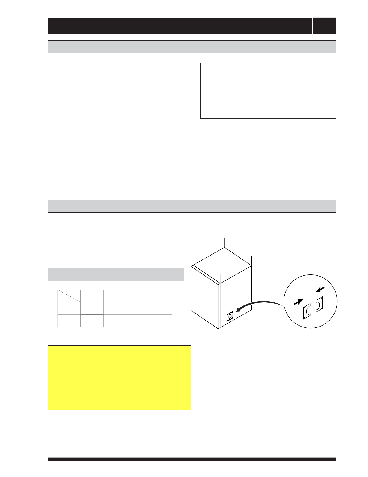
The size of the outlet for connecting copper pipe can be
adjusted by the fixing board.
Copper pipe connections
According to their practical situation,users can choose
the place on mainframe ( left or right ) for the out
of connecting copper pipe.
NOTE!
GHIURVWLQJWHPSHUDWXUHVHQVRUDQGRXWVLGH
WHPSHUDWXUHVHQVRUVKRXOGEHFRQQHFWHG
RXWOHWRIPDLQIUDPHDQGRXWGRRU
Copper tuble size
WRRXWGRRUXQLWWKURXJKWKHFRQQHFWLQJ
XQLW
/
/
/
Modle
Size
Gas
tube
5
/
8
"
5
/
8
"
3
/
4
"
3
/
4
"
Liquid
tube
3
/
8
"
3
/
8
"
1
/
2
"
1
/
2
"
SOLARIS DC SOLARIS DC SOLARIS DC SOLARIS DC
7 9 12 15
Pipe connections
9
Pipe connections for the heat medium side are made
at the top. All required safety devices, shut-off valves
(as close to the heat pump as possible), and particle
filter (supplied) are fitted.
When connecting to a system with thermostats on all
radiators, a relief valve must be fitted, or some of the
thermostats must be removed to ensure sufficient
flow.
Pipe connections (heating
medium) The heat pump´s water heater must be fitted with the
necessary valve equipment.
Pipe connections (water heater)
The heat pump should be supplemented with an elec-
tric water heater if a bubble pool or other significant
consumer of hot water is installed. The valve coupling
in COMPACT (electrical water heater) can be divided.
The mixing valve stays in COMPACT and the remain-
ing valve coupling can be used for incoming cold
water in DC AWA-SS series.
P
EXP
HW
CW SAV
SAV
VENTING VALVE
NOTE!
7KHYHQWLQJYDOYHVKRXOGEHVHWRQ
WKHWRSRIWKHKHDWLQJPHGLXPV\VWHP
SF
Notice
2. in line filter on the return line;
3.To clean system with a power flush before installing
the heat pump and fill with clean water;
4. To use flow gauge to get the correct flow for each unit.
SF Particle filter

Pipe connections
10
How to connect the copper pipes
Piping Connecton
Attention :
When connectiong the pipe, a suitable pitching spanner must be used. If other spanner is used, it may
damage the joint due to inappropriate force.
4. Connect the electric cable as per circuit diagram, and bundle
it with the connecting pipe.
1. Open the cover of the outdoor unit.
2. Connect the pipe to the indoor unit and outdoor unit.
Align the centre of the pipe and fully screw in the angular nuts with Finger.
On connecting the pipe, one should ensure that the insulating material of the pipe be closely fitted to
the nuts at the joint.
On connecting to theexternal unit, the pipeshould be wrapped with sponge padding to prevent
rain water from flowing in.
When bending the pipe,the radius cannot be too small and be about 150 160 mm.
connecting pipe
thick pipe
end nut
Connector
low pressure valve
high pressure valve
thin pipe
3. Use Vacuum pump to remove the air from indoor unit and
connection pipe.
Wipe the quick connectors with clean cloth to prohibit dust and impurity entering the pipes.
5. Take off the nuts in the mouths of high valve and low valve, turn
the valves core anticlockwise with hexagon panner till the valves
are opened completely. Recover and tighten the nuts.
6. Check leakage: check if there is leakage at each connection of the
pipes or nuts. If yes, remedial neasure must be taken, leakage is
not permitted in any case.

Pipe connections
11
If the outdoor unit needs to be disconnected and moved to another place, please recycle the
gas back into the compressor according to the following steps before doing the disconnecting:
The step and diagram of collect refrigerant
Liquid valve
Gas valve
Valve key
Liquid valve
Gas valve
Valve key
Liquid valve
Gas valve
20 seconds
Liquid valve
Gas valve
5. Tighten the cap of two valves.
6. loose the nut of the connect pipe to the outdoor unit valve with 2 spanner, disconnect the connect pipe
and the two valves.
2. Remove the cap of two valves with the spanner.
3. Tighten the core of the liquid valve (the smaller one) with valve key at first . After about 20 seconds, tighten
the core of the gas (the bigger one) with valve key.
1.Turn to the menu: OPERATION---MAN TEST
SET TO
was stopped.
4. Exit the " MAN TEXT "at once or turn the " WARM PUMP " ," OUT FAN " ," CMP " to OFF,at that time the
HEATPUMP
ADD 1
3 WAY
4 WAY
WARM PUMP
MAN TEST
OFF
OFF
OFF
OFF
OUT FAN OFF
CMP OFF
ADD 2 OFF
ADD 3 OFF
ADD 1
3 WAY
4 WAY
WARM PUMP
MAN TEST
OFF
OFF
OFF
ON
OUT FAN ON
CMP ON
ADD 2 OFF
ADD 3 OFF
Pipe connections
12
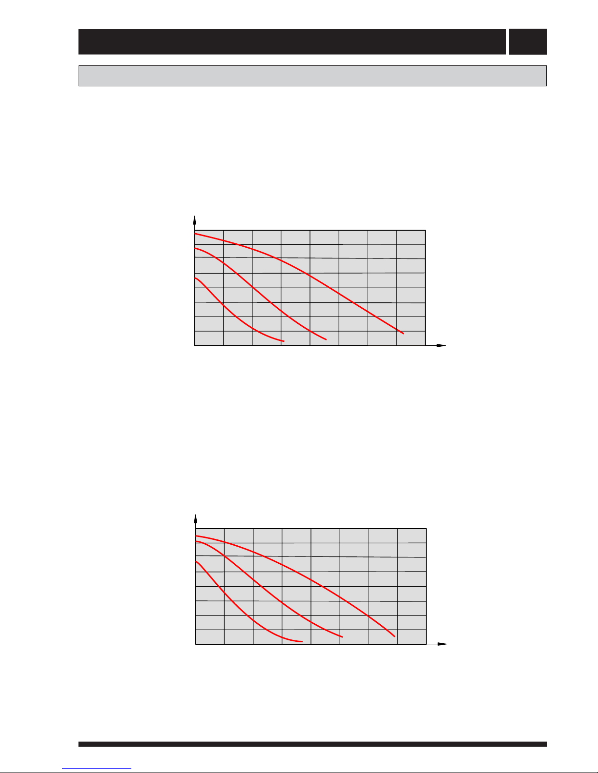
Pump capacity diagrams, heating medium side
kPa
DC AWA-SS-7 / DC AWA-SS-9 / DC AWA-SS-12
Available
pressure
Flow
l/s
1
2
3
0.22 0.44
0.66
0.88 1.10 1.32
80
70
60
50
40
30
20
10
0
1.54 1.76
0
DC AWA-SS-15
kPa
Tillgängligt tryck
Available
pressure
Flow
1
2
3
0.28 0.56
0.84
1.12 1.41.68
80
70
60
50
40
30
20
10
0
1.96 2.24
0
l/s
WILO RS-25/8
WILO RL-25/7.5
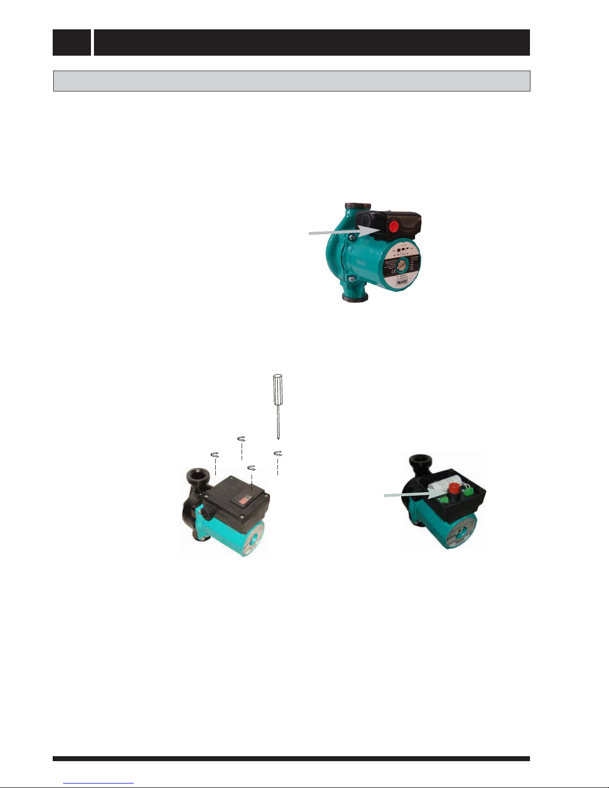
Pipe connections
13
The pump is
adjustable to adjust
the flow: 1, 2, or 3.
The pump is
adjustable to adjust
the flow: 1, 2, or 3.
WILO RS-25/8
WILO RL-25/7.5
How to adjust the rate of flow

Electrical connection 14
NOTE!
(OHFWULFDOLQVWDOODWLRQDQGVHUYLFHPXVW
EHFDUULHGRXWXQGHUWKHVXSHUYLVLRQRI
DTXDOLILHGHOHFWULFLDQLQDFFRUGDQFH
ZLWKWKHVWLSXODWLRQVLQIRUFH
Connect the power cord
( 230V / 50 HZ )
L
N

Electrical connection15
Step1 Step3Step2
Step1 Step3Step2
Wiring of the terminal (mode one)
Wiring of the terminal (mode two)
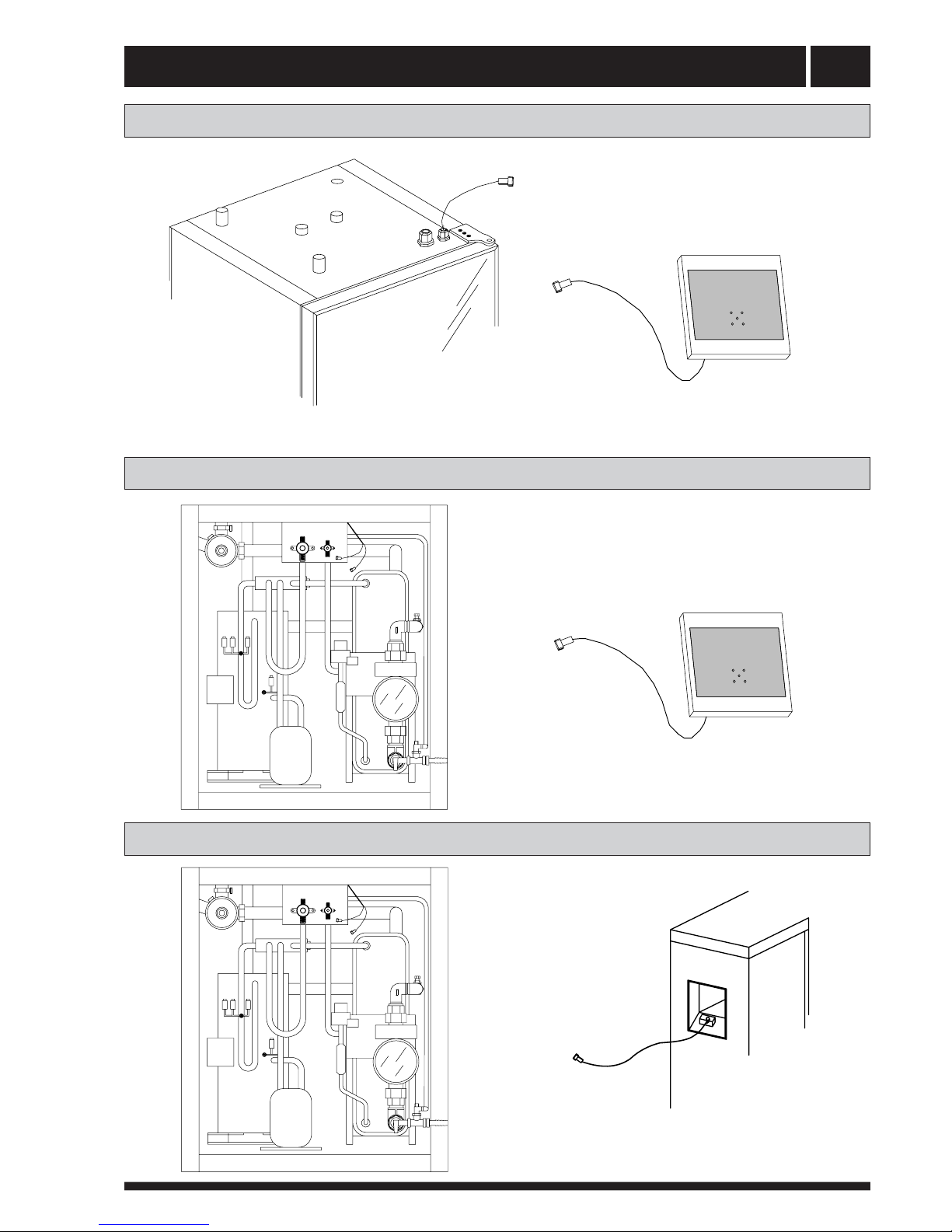
Electrical connection 16
Connecting The Room Temperature Sensor
Connecting The Outside Temperature Sensor
PG=Defrost temperature sensor
Outdoor unit
PG
Outside air temperature sensor
Outside air temperature sensor
PO=Outside air temperature sensor
Room temperature sensor
ROOM
Room temperature sensor
ROOM=Room temperature sensor
Connecting The Defrost Temperature Sensor
PO
PG
PO
PG
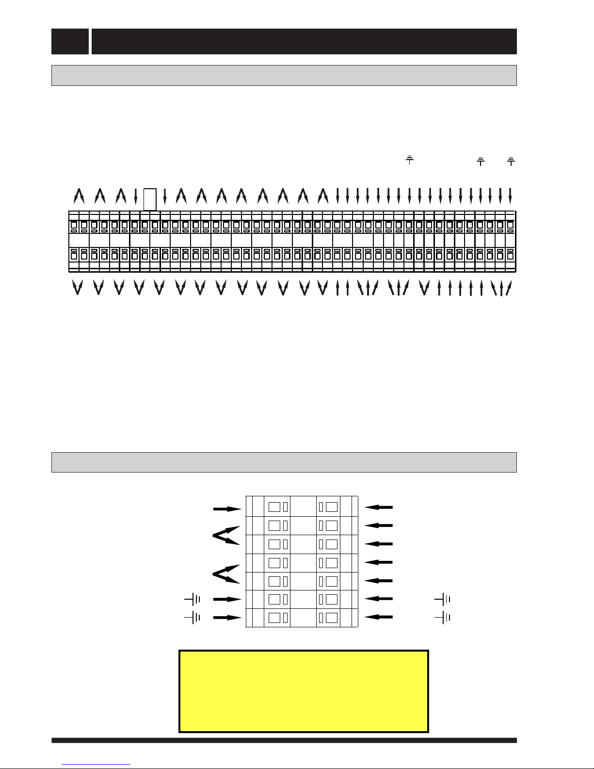
Electrical connection17
RETURN WTT FEED EHI WF ROOM HP LP
CSP
N
3WV
4WV
N
GND
WCP
N
N
GND
GND
WCP2
N
From PCB2 / T1
3-Way Valve's Relay ( port 3)
From PCB2 / CN6
From Water return Temperature Sensor
From Water feed Temperature Sensor
From Defrost Temperature Sensor
From Outside Air Temperature Sensor
From Room Temperature Sensor
From Water Tank Temperature Sensor
From Compressor Exhaust
Temperature Sensor
From High Pressure Pressostat
From Low Pressure Pressostat
From
From
From Water Flow Switch
From Three-way valve forwaterflow
From Four_way Valve
From Water cycle pump
From Outdoor Unit FAN-LOW-L
From Water cycle pump2
From Common Terminal (CT)
1.5mm2 terminal connection
EH4
From Oudoor Unit Eletrical heater 4-L
NOTE!
7KHFRQQHFWLQJZLUHRIRXWGRRUXQLWIDQ
ZDWHUF\FOHSXPSWZRDQGHOHFWULFDOKHDWHUIRXU
VKRXOGEHFRQQHFWHGWRWKHPP
2
WHUPLQDO
WKURXJKWKHKROHRQWKHVRXQGLQVXODWLRQERDUG
DQGFRQQHFWWRRXWVLGHZLWKWKHFRSSHUSLSHV
3-Way Valve's Relay ( port 1)
HDO PO
From Electrical auxiliary heater
Temperature Sensor
From Outdoor Unit FAN-N /Outdoor EH4-N
From Outdoor Unit FAN GND
From PCB2 / CN2 N-IN
connect together
From External relay signal control port
From Compressor stop protection
2.5mm2 terminal connection
EH1
EH2
N
EH3
N
GND From
From Compressor
From Electrical heater 3
From Electrical heater 2
From Electrical heater 1 From Fuse 1
From Fuse 2
From Fuse 3
From K1 N
GND From
From Electrical heater
From K1 N
PG PQ
OFAN
-H
OFAN
-L
From Outdoor Unit FAN-HIGH-L
From PCB2 / T2
From PCB2 / T3
From PCB2 / CN15
From PCB2 / CN15
From PCB2 / CN14
From PCB2 / T4
From MAIN PCB / CN22
From MAIN PCB / CN24
From MAIN PCB / CN23
From MAIN PCB / CN15
From MAIN PCB / CN15
From MAIN PCB / CN15
From
From MAIN PCB / CN21-L
From MAIN PCB / CN21-N
From MAIN PCB / CN14 OFAN-H
From MAIN PCB / CN13 OFAN-L
From MAIN PCB / CN11-N
From Common Terminal (CT)
From MAIN PCB / CN11N(AC)-OUT
From PCB2 / CN2 N-IN
From Water Temperature Thermostat 1 (WTP1 40C)
From Water Temperature Thermostat 2 (WTP2 70C)
From Switch Board E-HEATER port
From AC Contactor - A2
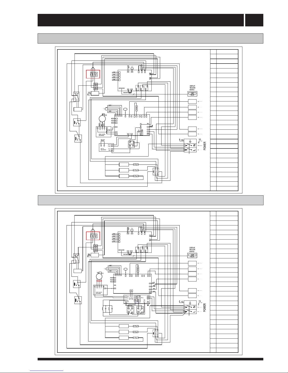
Electrical connection 18
Indoor Unit Wiring Diagram of DC AWA-SS-12 / 15
Indoor Unit Wiring Diagram of DC AWA-SS- 7 / 9
CN4
CN6
CN17
CN8
Cn11
N(AC)-OUT
P6 P3
CN10 CN1
CN9
CN2
CN614
CN27
CN16-N
CN16-L
CN21-L
CN21-N
CN11-N
CN11-L
LL
CN5
CN15
CN23
CN24
LP
HP
4WV
EXPANSION
VALVE
PO
PG
PQ
MAIN
PCB
P1
5
5
YELLOW
BLUE
RED
P1
CN22
COMPRESSOR PRESSURE
RELIEF SWITCH
CSP
CN 14 OFAN-H
CN 13 OFAN-L
CN 6CN 8
CN 4 CN 5
CN 27
T 1
PCB2
L-IN
T 2
T 3
T 4
COM NO
COM NO
COM NO
CN 1
CN 2
CN 3
N-IN
S
CN 14CN 15
3WV
7
8
1
3
2
4
5
6
A1 A2
WCP
4
FEED
RETURN
WTT
EHI / WF
ROOM
WCP 2
N
N
OFAN-L
OFAN-H
EH 4
K1
F2 [ 15A ]
F1 [ 15A ]
F3 [ 15A ]
EH 2
EH 1
EH 3
SB
HDO
BROWN
BLACK
RED
BLUE
BLACK
BLACK
BLACK
BLACK
BLUE
BLACK
BLUE
BLUE
BLACK
BROWN
BLACK
BLACK
BLUE/WHITE
WHITE
BLUE/YELLOW
BLACK
BLACK
BLACK
BLACK
BLACK
BROWN
BLUE
BLACK
WHITE
BLACK
WHITE
WHITE
WVU
WTP1
WTP2
RE
EV
CM
CT
AC
BLACK
BLACK
BLUE
BLUE
RED
BLUE
BLUE
BLACK
BLACK
BLACK
BLACK
BLACK
BLACK
BLACK BLUE
BLACK
K1 Air Break Switch
AC AC
Contactor
SB Switch Board
CM Compressor
PCB Circuit Board
3WV 3 Way Valve
4WV 4 Way Valve
WCP Water
Circulating Pump
WCP2 Water
Circulating Pump 2
OFAN Outdoor Unit Fan Motor
CT Common Terminal
RE Relay for 3 Way Valve
EH 1 Electrical Heater 1
EH 2
EH 3
Electrical Heater 2
Electrical Heater 3
EV Electronic Expansion Valve
EHI/WF Electric Heater
Interruptor / Water Flow Switch
CSP Compressor
Stop Protection
LP Low Pressure Switch
HP High Pressure Switch
HDO External Signal Controls
Heat Pump Start and Stop
WTT
ROOM
PO
PG
FEED
RETURN
Water Tank
Temperature Sensor
Room
Temperature Sensor
Ambient
Temperature Sensor
Defrost
Temperature Sensor
Water Feed
Temperature Sensor
Water Return
Temperature Sensor
WTP Water
Temperature Thermostat
EH 4 Electrical Heater 4
PQ Exhaust
Temperature Sensor
CN 4
CN 6
CN17
CN8
CN 18
CN614
CN27
CN 14
CN 13
CN16-N
CN16-L
CN21-L
CN21-N
CN19-N
CN19-L
CN5
CN15
CN23
CN24
LP
HP
EXPANSION
VALVE
OUTDOOR
MAIN PCB
5
5
BLUE
CN22
COMPRESSOR PRESSURE
RELIEF SWITCH
CSP
RED
CN 8
CN 35
CN 6CN 8
CN 4 CN 5
CN 27
T 1
PCB2
L-IN
T 2
T 3
T 4
COM NO
COM NO
COM NO
CN 1
CN 2
CN 3
N-IN
S
CN 14CN 15
3WV
7
8
1
3
2
4
5
6
A1 A2
WCP
4
FEED
RETURN
WTT
EHI / WF
ROOM
WCP 2
N
N
OFAN-L
OFAN-H
EH 4
K1
F2 [ 15A ]
F1 [ 15A ]
F3 [ 15A ]
EH 2
EH 1
EH 3
SB
HDO
BROWN
BLACK
RED
BLUE
BLACK
BLACK
BLACK
BLACK
BLUE
BLUE
BLACK
BROWN
BLACK
BLACK
BLUE/WHITE
WHITE
BLUE/YELLOW
BLACK
BLACK
BLACK
BLACK
BLACK
BROWN
BLUE
WTP1
WTP2
RE
CT
AC
BLACK
BLACK
BLUE
BLUE
RED
BLUE
BLUE
BLACK
BLACK
BLACK
BLACK
BLACK
BLACK
BLACK BLUE
BLACK
4WV
PO
PG
PQ
EV
WUV
BROWN
WHITE
BLUE
K1 Air Break Switch
AC AC
Contactor
SB Switch Board
CM Compressor
PCB Circuit Board
3WV 3 Way Valve
4WV 4 Way Valve
WCP Water
Circulating Pump
WCP2 Water
Circulating Pump 2
OFAN Outdoor Unit Fan Motor
CT Common Terminal
RE Relay for 3 Way Valve
EH 1 Electrical Heater 1
EH 2
EH 3
Electrical Heater 2
Electrical Heater 3
EV Electronic Expansion Valve
EHI/WF Electric Heater
Interruptor / Water Flow Switch
CSP Compressor
Stop Protection
LP Low Pressure Switch
HP High Pressure Switch
HDO External Signal Controls
Heat Pump Start and Stop
WTT
ROOM
PO
PG
FEED
RETURN
Water Tank
Temperature Sensor
Room
Temperature Sensor
Ambient
Temperature Sensor
Defrost
Temperature Sensor
Water Feed
Temperature Sensor
Water Return
Temperature Sensor
WTP Water
Temperature Thermostat
EH 4 Electrical Heater 4
PQ Exhaust
Temperature Sensor
Reactor 1
Reactor 2
Capacitor 1
Capacitor 2
Table of contents
Other SERO Heat Pump manuals
 Manual")


Popular Heat Pump manuals by other brands

EMI
EMI S2HA Installation, operation and maintenance manual

Immergas
Immergas MAGIS M4-6-8 EH3 Instructions and Recommendations

Vaillant
Vaillant uniTOWER plus operating instructions

Bryant
Bryant 661C Installation and start-up instructions

COSMOGAS
COSMOGAS ECOTWIN Installation, use and maintenance manual

Kaysun
Kaysun Aquantia KHPS-MO Series Installation & owner's manual


York
York YMGE36BNO-MS-X user manual

Hamilton Engineering
Hamilton Engineering EVO 299 Maintenance procedures

Dimplex
Dimplex LI 16TE Installation and operating instructions

LG
LG LMU247HV Specifications

MICROWELL
MICROWELL HP 1100 GREEN INVERTER PRO Installation and user manual

Allied
Allied 4SHP15LE Service manual