
System description
Principle of operation ............................................ 3
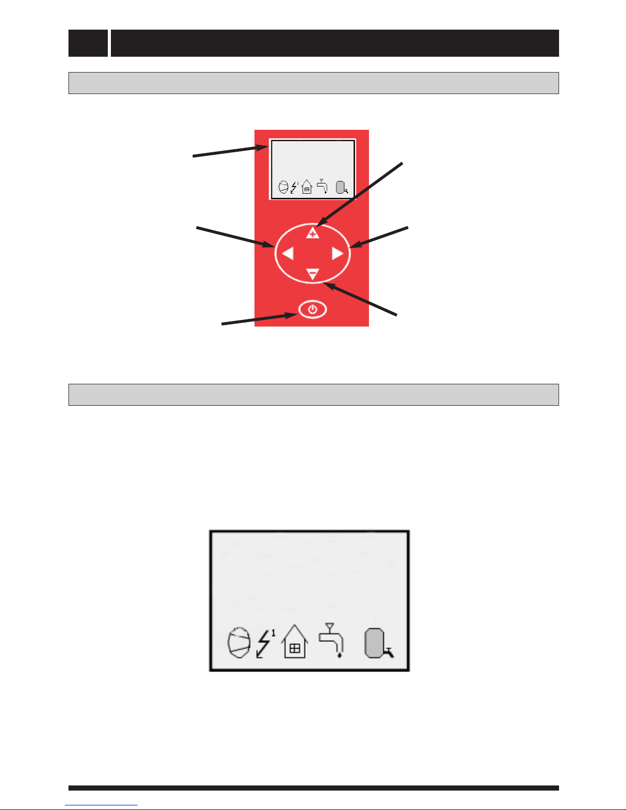
Control panel
Layout .................................................................. 5
Explanation .......................................................... 5
General information for the installer
Transport and storage ............................................ 7
Installation .............................................................. 7
Guideline values for collectors .............................. 7
Inspection of the installation .................................. 7
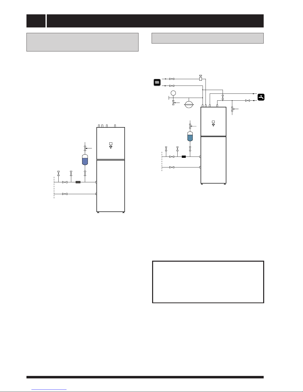
Pipe connections
General .................................................................. 8
Pipe connection (collector) .................................... 8
Pipe connection (heating medium) ........................ 9
Pipe connections (water heater) ............................ 9
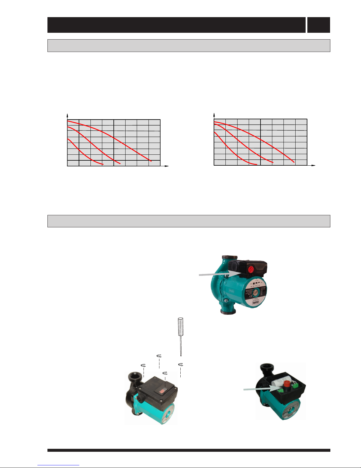
Pump capacity diagrams, heating medium side .. 10
Pump capacity diagrams, collector side .............. 11
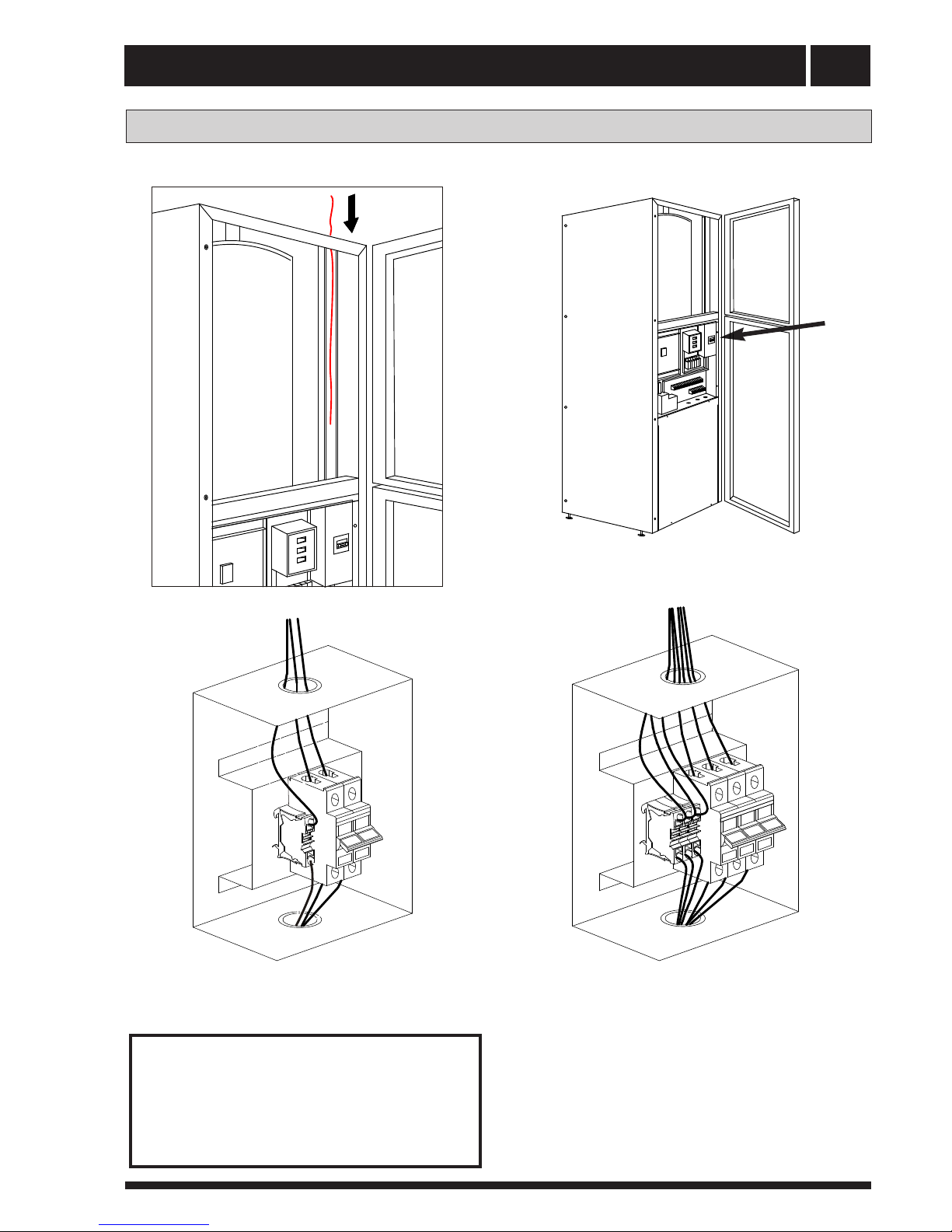
Electrical connections
Wiring of the terminal (mode one)......................... 13
Connecting the room temperature sensor ........... 14
Layout of the PCB ............................................. 15
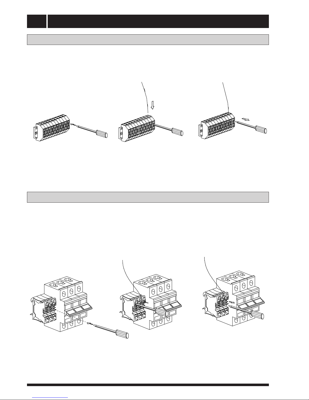
1.5mm2 terminal connection ............................. 15
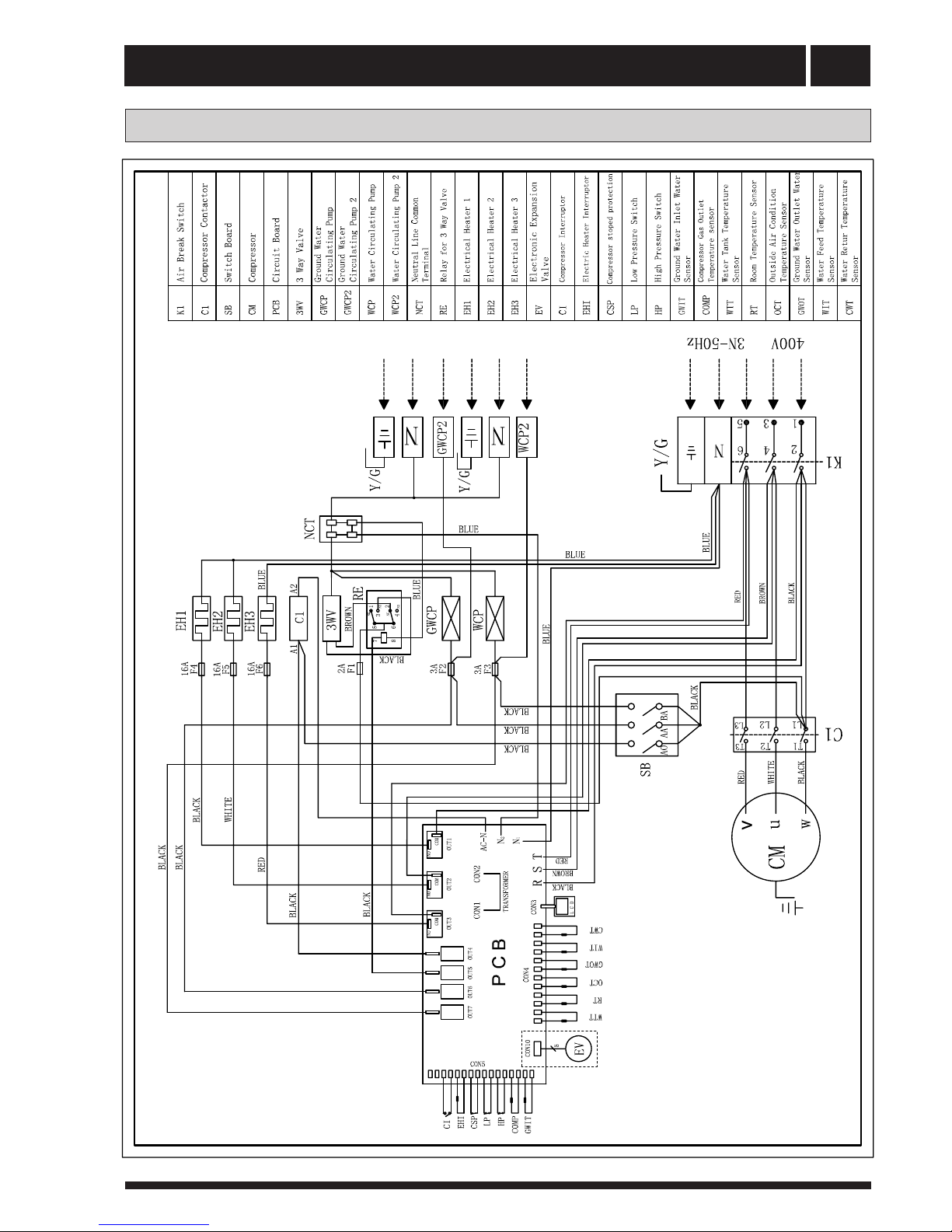
Part of wiring diagram ........................................ 16
2.5mm2 terminal connection ............................... 16
Wiring diagram ( 230v / 50 Hz ) ............................ 17
Commissioning and adjusting
Preparations ........................................................ 19
Filling and venting the collector system .............. 19
Filling the heating medium system ...................... 19
Internal air vent valve, brine ................................ 19
Inspection ............................................................. 20
Readjusting, heat medium side ............................ 20
Readjusting, collector side .................................. 20
Emptying the water heater .................................. 20
Main Menu Information ......................................... 22
Sub-menu Operation.............................................. 22
Sub-menu Heat Curve........................................... 23
Sub-menu Temperature ........................................ 24
Sub-menu Operating Time .................................... 27
Adjustments to be made regularly ........................ 28
Heat Generation-General....................................... 28
Adjustment of the CURVE valve ........................... 29
Adjustment of ROOM valve.................................... 31
Adjustment of Part of the Heat Curve .................... 31
Adjustment the MIN and MAX valve ..................... 32
Adjustment of the HEAT STOP valve......................33
Maximum Return Line Temperature ..................... 35
Warm water Production........................................... 35
Regular checks.......................................................36
Check of the Operating Mode............................... 36
Checking the Brine Level in the Brine system ...... 36
Dealing with malfunctions
Draining, heat medium side ................................ 41
Draining, collector side.......................................... 41
Component placement
Component positions 1 ........................................ 42
Component positions 2......................................... 43
Component positions 230 V / 50 HZ .................... 44
Component positions 3 x 400 V / 3 / 50 HZ ......... 44
List of components
List of components................................................ 45
Dimensions
Dimensions and setting-out coordinates .............. 46
Accessories
Accessories .......................................................... 47
Technical specifications
Technical specifications 230 V ............................ 48
Technical specifications 3 x 400 V ...................... 49
Unit Description .................................................... 3
Principle of heatpump ........................................... 4
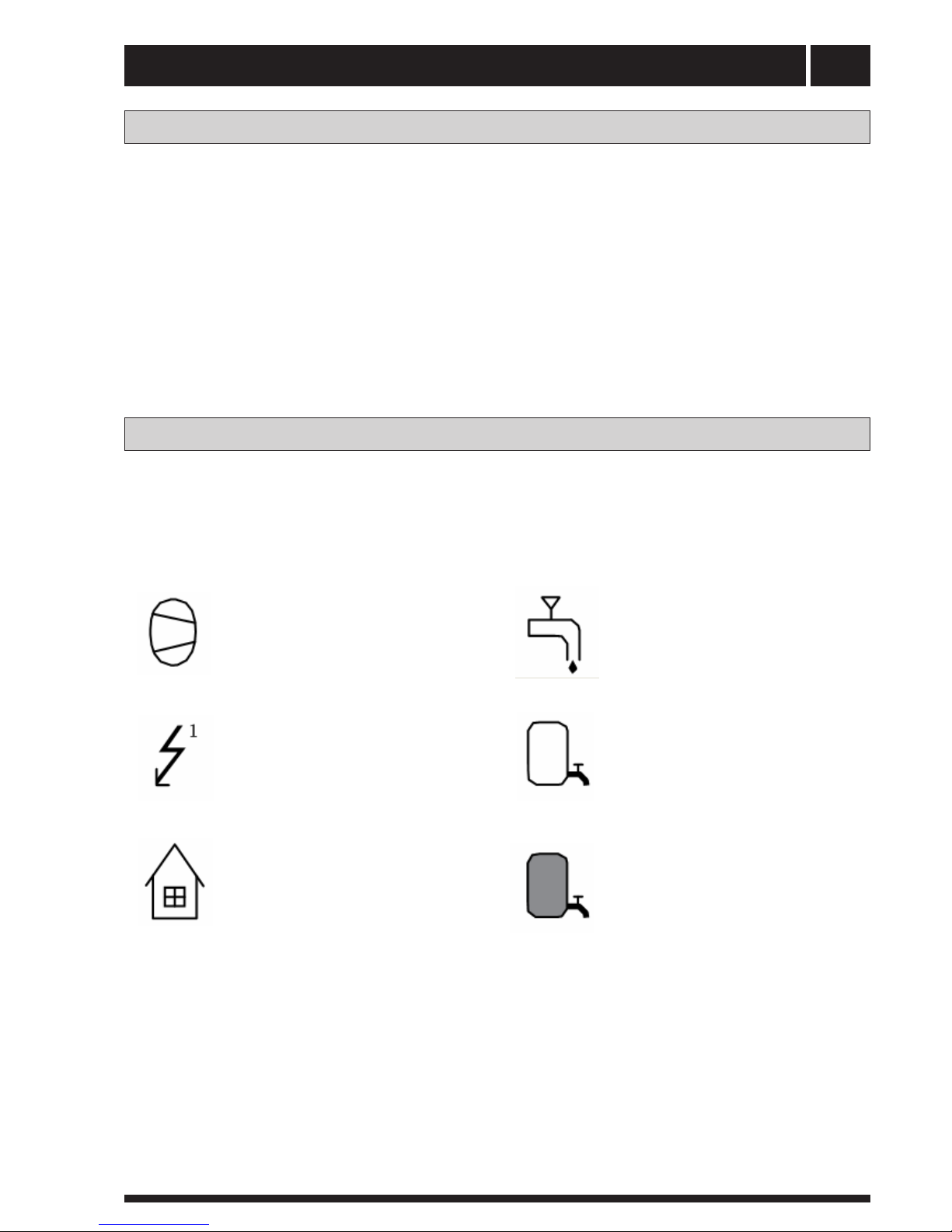
Functions ............................................................. 6
Symbols ............................................................... 6
How to adjust the rate of flow .............................. 10
Connect the power cord ....................................... 12
Wiring of the terminal (mode two)......................... 13
Connecting the outside temperature sensor ........ 14
Wiring diagram ( 3X400v / 3 / 50 Hz ) ................... 18
Graph of recent change in TEMPERATURE............34
Checking the Water Level of the Heating system .37
Checking the safety valves.................................... 37
In the event of leakage.......................................... 37
Alarm Messages.................................................... 38
Terminology and Abbreviations............................. 39
Draining, water tank.............................................. 41
Draining, the chassis............................................. 41
Enclosed kit .......................................................... 47
Adjust the brine and the heating medium pump ... 20
Sub-menu Integral ................................................. 24
Sub-menu Reset ................................................... 28
Sub-menu Man Test .............................................. 28
Control
General Information .............................................. 21
Menus ................................................................... 22
Description of the switch board............................. 40
Degree Minute's(DM) instruction .......................... 25


 Manual")


