334000 Autry Street, Livonia, MI 48150 • 800.968.5530 • Fax 734.419.0209 • www.hamiltonengineering.com • LIT91178 REV 5/2017
Page 5 of 9
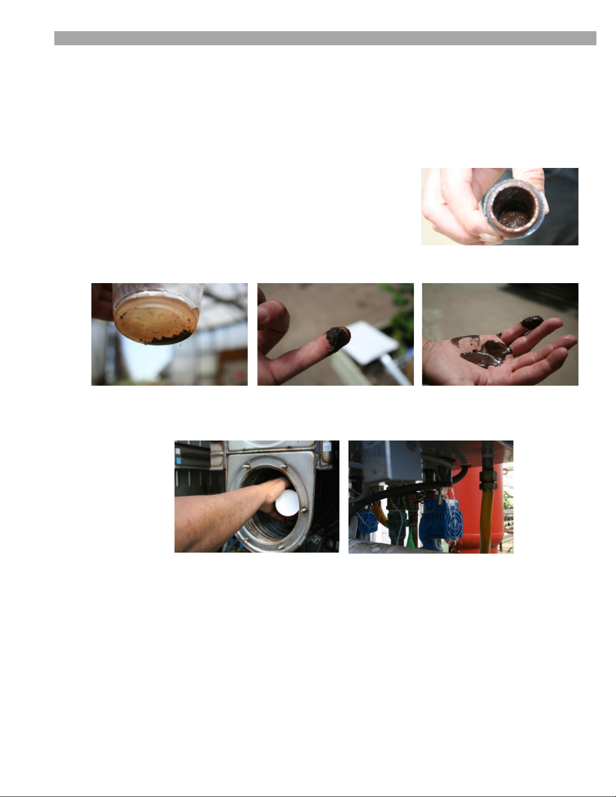
TESTING
The following steps require the power supply be turned back on; extreme caution must be exercised
when performing service with the power supply on and the door off.
•Whenturningtheappliancebackon,listenforsignicantnoisesfromthefanandpump.Also,inspect
for leaks at the pump connections.
• Press the reset button from the home screen to access the sensor readings, and record each reading,
making sure that all sensors and thermometers are reading the same, with the heat off.
•Firetheapplianceonmaximumoutputfor5minutes,inordertocheckthe∆Tfromtheinletsensorto
the outlet sensor.
-Ifthe∆Treadingisoutofdesignrangebymorethan10%orthereisanE6erroronthe
display,refertocoilcleaninginstructionsbelow.Record∆Ttotrackanyincreasesfromone
year to the next.
• Fire the appliance on maximum output, and measure and adjust the CO2percentage as required.
• Fire the appliance on minimum output, and measure and adjust the CO2percentage as required.
•IfthereareanunusualnumberofF5orF6faultsorifcombustionisoffsignicantly,gassupply
pressuremustbeveriedatstatic(noload)andfullbuildingloadconditions.
•SeeTable3-3,Page17forspecicsettings.
•Inspectintakeandexhaustscreensattheterminationpointforsignsofcontamination(i.e.leaves,twigs,etc).
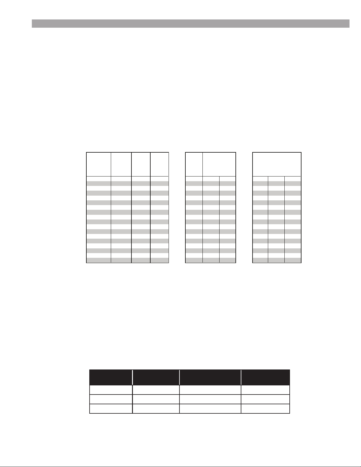
•Adifferentialpressure(∆P)readingshouldbetakenacrosstheexhaustandinletairconnectionpoints
ofeachappliancetoconrmthatitisbelowthemaximumshownbelow.
NOTE: The inlet air pressure should be negative.
MODEL AIR PRESSURE
(∆P) MODEL AIR PRESSURE
(∆P)
HW129 < .6” wc HW399 < 1” wc
HW179 < .96” wc HW599 < .86” wc
HW199.1 < .68” wc HWH 1499-1999 < .8” wc
Hamilton EVO Products
Flow and Pressure Drop (GPM Feet of Head)
Design
HW 79 - 129 (.8) HW 179 - 199.1 (.8) HW 299 HW 399 HW 599 HW 1499 HW 1999
Flow Rate
GPM Head GPM Head GPM Head GPM Head GPM Head GPM Head GPM Head
2.2 1.8 3.5 2.1 6.6 3.4 13.2 4.8 22.0 5.9 52.8 6.3 70.4 6.2
3.3 4.6 4.4 3.9 8.8 6.0 15.4 6.5 24.2 7.2 57.2 7.4 76.3 7.4
Hydronic 4.4 (4) 7.9 6.6 (5) 7.9 11.0 9.3 17.6 8.5 26.4 9.4 61.6 8.6 82.2 8.6
5.3 11.6 7.7 12.5 13.2 13.4 19.8 10.8 30.8 11.6 70.5 11.2 99.8 12.6
6.2 15.4 8.8 15.2 15.4 18.3 22.0 13.4 35.2 15.2 79.3 14.2 111.5 15.8
DHW - direct 6.6 17.7 9.9 17.7 16.5 21.1 26.4 19.2 39.6 21.3 92.5 19.3 123.3 19.3
7.7 24.1 11 21.5 17.6 23.9 30.8 26.2 41.8 21.4 96.9 21.2 129.2 21.2
8.8 31.5 12.1 29.5 19.8 30.2 33.0 30.1 44.0 23.7 101.3 23.1 135.0 23.1
Model
BTU/hr.
Input
Flow
∆P at
Flow
Rate - ft.
of head
Hydroni
c Pipe
Size
DHW
Pipe
Size
HWH 79 80,000 2.23 3.3 1" 34.6 19.2 1"
HWD 79 80,000 23.5 13.1
HWH 129 136,300 3.64 3.5 1" 58.9 32.7 1"
HWD 129 136,300 40.1 22.2
HWH 179 186,600 5.06 3.3 1" 53.7 29.8 1"
HWD 179 186,600 36.6 20.3
HWH 199.1 199,999 5.63 3.5 1" 57.6 32.0 1"
HWD 199.1 199,999 39.2 21.8
HWH 299 300,000 8.45 4.9 1.5" 51.8 28.8 1.5"
HWD 299 300,000 35.3 19.6
HWH 399 399,999 11.31 3.5 1.5" 43.2 24.0 2"
HWD 399 399,999 29.4 16.3
HWH 599 630,000 17.74 4.9 1.5" 45.3 25.2 2"
HWD 599 630,000 30.9 17.1
HWH 1499 1,500,000 42.13 5.2 2.5" 46.3 25.7 2.5"
HWD 1499 1,500,000 31.5 17.5
HWH 1999 1,999,999 58.45 5.2 2.5" 46.3 25.7 2.5"
HWD 1999 1,999,999 31.5 17.5
Design ∆T
Hydronic @ 95%
Design ∆
DHW @ 97%
Effective 11/2007 - Added minimum flow and pressure drop 3.09
34000 Autry Street, Livonia, MI 48150 • 800.968.5530 • Fax 734.419.0209 • www.hamiltonengineering.com • LIT91149 REV 4/2009
ANNUAL INSPECTION CONT.