Servoflo mp6-QuadEVA User manual

(03.2018) rev.4
1
Bartels Mikrotechnik GmbH, Konrad-Adenauer-Allee 11, 44263 Dortmund, Germany
www.bartels-mikrotechnik.de, info@bartels-mikrotechnik.de
Tel: +49-231-47730-500, Fax: +49-231-47730-501
Operating Manual
for
mp6-QuadEVA board

(03.2018) rev.4
2
Bartels Mikrotechnik GmbH, Konrad-Adenauer-Allee 11, 44263 Dortmund, Germany
www.bartels-mikrotechnik.de, info@bartels-mikrotechnik.de
Tel: +49-231-47730-500, Fax: +49-231-47730-501
Content
1Introduction....................................................................................................................................................................... 3
2Proper use........................................................................................................................................................................... 3
2.1 Intended purpose.................................................................................................................................................... 3
2.2 Misuse........................................................................................................................................................................ 3
2.3 Staff selection and qualification ........................................................................................................................ 3
2.4 Safety notice............................................................................................................................................................ 4
3Overview ............................................................................................................................................................................. 5
4Interface and mode of operation ................................................................................................................................. 7
4.1 Push-button ............................................................................................................................................................. 7
4.2 Rotary knob: pump voltage.................................................................................................................................. 7
4.3 Rotary knob: pump frequency ............................................................................................................................. 8
4.4 Operation via USB port (after installation of the drivers)............................................................................ 8
4.5 Local control ............................................................................................................................................................ 9
4.6 Installation of the USB driver.............................................................................................................................. 9
4.6.1 For “Windows XP” and former Windows versions..................................................................................... 9
4.6.2 For “Windows 7”...............................................................................................................................................10
4.6.3 For "Windows 8"...............................................................................................................................................10
4.7 Software..................................................................................................................................................................11
5Maintenance....................................................................................................................................................................12
5.1 Cooling.....................................................................................................................................................................12
5.2 Exchanging the micropump ...............................................................................................................................12
6Dimensions.......................................................................................................................................................................13
7Technical data and Performance charts ...................................................................................................................14
8Serial solution..................................................................................................................................................................15

(03.2018) rev.4
3
Bartels Mikrotechnik GmbH, Konrad-Adenauer-Allee 11, 44263 Dortmund, Germany
www.bartels-mikrotechnik.de, info@bartels-mikrotechnik.de
Tel: +49-231-47730-500, Fax: +49-231-47730-501
1Introduction
The mp6-QuadEVA is an evaluation board that allows to control up to four mp6 micropumps
simultaneously with one setting and up to a frequency of 800 Hz.
It is possible to change pump voltage and pump frequency directly with the rotary control elements at the
board or via USB. Simple control software is provided with the board. Also any terminal software can be
used to remotely control frequency and amplitude or enable/disable each of the four pumps.
2Proper use
2.1 Intended purpose
The mp6-QuadEVA was designed to control up to four micropumps for gas pumping, i.e. four pieces of
mp6-AIR micropumps.
Nevertheless it is also possible to pump liquids, either with the mp6-AIR, mp6-pp or the standard mp6
pump; though the higher frequencies will not result in a performance boost.
If liquids should be pumped, please regard the following:
The micropump is intended for pumping liquids or gases with varying flow rates controlled by the
electronics. The mp6-QuadEVA controller is intended as a pump driver for mp6-AIR/mp6/mp6-pp.
Any other use of the micropump or controller unit is deemed improper.
Do not make any modifications or extensions to the pump or controller without the prior written consent of
the manufacturer. Such modifications may impair the safety of the unit and are prohibited! Bartels
Mikrotechnik GmbH rejects any responsibility for damage to the unit caused by unauthorized modifications
to the pump and risk and liability are automatically transferred to the operator.
2.2 Misuse
The use of gases or liquids which may alone or in combination create explosive or otherwise health-
endangering conditions (including vapors) is not permitted.
2.3 Staff selection and qualification
All work in connection with the installation, assembly, commissioning/decommissioning, disassembly,
operation, servicing, cleaning and repairing of the pump and the controller must be carried out by qualified,
(03.2018) rev.4
4
Bartels Mikrotechnik GmbH, Konrad-Adenauer-Allee 11, 44263 Dortmund, Germany
www.bartels-mikrotechnik.de, info@bartels-mikrotechnik.de
Tel: +49-231-47730-500, Fax: +49-231-47730-501
suitably trained and instructed personnel. Work on electrical components and assemblies must be carried
out by personnel with the necessary qualifications and skills.
2.4 Safety notice
The mp6-QuadEVA generates voltages of up to 260 Vpp. All parts of the evaluation board can carry
voltages in this range. Therefore, the board should only be used by qualified personnel. Although the output
power of the module is very low, proper insulation according to the application conditions needs to be
considered by the customer. This especially applies to the bottom side of the PCB. Contact with water or
other liquids needs to be prevented. The pump must not be unplugged while the board is active.
DANGER
THE EVALUATION BOARD CAN CARRY HIGH VOLTAGE!
BE CAREFUL, WHILE CONNECTING AND HANDLING THE BOARD!

(03.2018) rev.4
5
Bartels Mikrotechnik GmbH, Konrad-Adenauer-Allee 11, 44263 Dortmund, Germany
www.bartels-mikrotechnik.de, info@bartels-mikrotechnik.de
Tel: +49-231-47730-500, Fax: +49-231-47730-501
3Overview
The mp6-QuadEVA will only be available as a set of the following components:
mp6-QuadEVA Board
power supply 7.5 V; 1000 mA
Mini-USB cable
4x micropump mp6-AIR
software and driver CD (optional, software and driver will be send via Email)
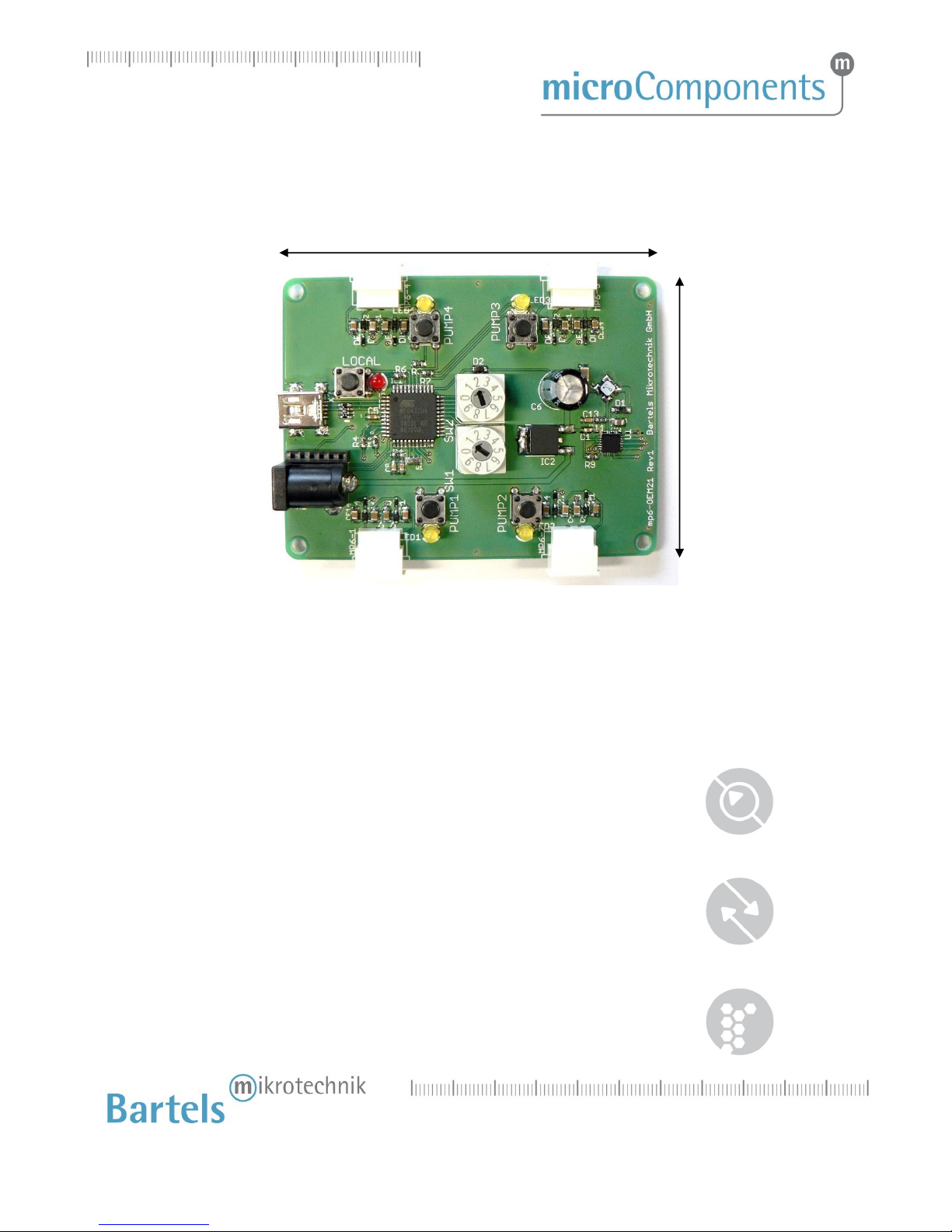
Figure 1 Overview of the mp6-QuadEVA board
In the figure above the parts are:
1. Molex connector for flexible wire of the mp6 (one per pump)
2. Push-button to switch back to local control
3. LED signaling USB driving mode
1
4
6
8
7
9
5
3
2
(03.2018) rev.4
6
Bartels Mikrotechnik GmbH, Konrad-Adenauer-Allee 11, 44263 Dortmund, Germany
www.bartels-mikrotechnik.de, info@bartels-mikrotechnik.de
Tel: +49-231-47730-500, Fax: +49-231-47730-501
4. Mini USB connector
5. DC connector
6. LED signaling activated pump (one per pump)
7. Rotary knob for pump voltage setting (SW1)
8. Rotary knob for pump frequency setting (SW2)
9. Push-button to turn the pump on/off (one per pump)
(03.2018) rev.4
7
Bartels Mikrotechnik GmbH, Konrad-Adenauer-Allee 11, 44263 Dortmund, Germany
www.bartels-mikrotechnik.de, info@bartels-mikrotechnik.de
Tel: +49-231-47730-500, Fax: +49-231-47730-501
4Interface and mode of operation
The board does not have any main switch. When connecting the power supply to the DC connector (5) the
board is ready for operation. Connecting to a PC is optional. The board can be operated without PC
connection. However, if connected to an USB-power supply or an USB-port the power connection via DC
connector is still necessary.
4.1 Push-button
The four push–buttons (9) allow turning the individual pumps on or off. If turned on the corresponding
LED (6) will be illuminated.
4.2 Rotary knob: pump voltage
Through rotation of the rotary knob “SW1” (7) the pump voltage of all pumps can be changed, please use a
small flat blade screwdriver. The following table lists which voltage corresponds to the positions:
position SW1
pump voltage
0
0 Vpp
1
40 Vpp
2
80 Vpp
3
116 Vpp
4
150 Vpp
5
175 Vpp
6
200 Vpp
7
220 Vpp
8
240 Vpp
9
260 Vpp
Figure 2 Pump voltage at rotary knob SW1
(with four connected pumps and a frequency of 100 Hz)
The pump voltage may vary due to the number of connected pumps. With more pumps to operate the load
increases, hence the max voltage decreases. The pump voltage can also decrease a bit when operating with
higher frequencies.

(03.2018) rev.4
8
Bartels Mikrotechnik GmbH, Konrad-Adenauer-Allee 11, 44263 Dortmund, Germany
www.bartels-mikrotechnik.de, info@bartels-mikrotechnik.de
Tel: +49-231-47730-500, Fax: +49-231-47730-501
4.3 Rotary knob: pump frequency
With the rotary knob “SW2” (8) it is possible to change the frequency for all pumps, please use a small flat
blade screwdriver. The table below lists the possible frequencies:
position SW2
pump frequency
0
50 Hz
1
75 Hz
2
100 Hz
3
200 Hz
4
300 Hz
5
400 Hz
6
500 Hz
7
600 Hz
8
700 Hz
9
800 Hz
Figure 3 Pump frequency at rotary knob SW2
The control signal to the pumps is a pure sine signal. Therefore it is not the same as with the mp6-OEM.
4.4 Operation via USB port (after installation of the drivers)
The driving parameters can be set via your PC. For this purpose any terminal software can be used that is
capable of sending commands to serial COM-Ports. In the example below the Windows software
HyperTerminal is used. As the HyperTerminal is not available in Windows 7 anymore, we recommend
freeware terminal software like PuTTY (http://www.putty.org).
On the driver CD supplied in the set you will find simple control software that can be used for evaluation
(see chapter 4.7).
HyperTerminal example:
Step 1: Connect the power supply to the board.
Step 2: Connect the board to your computer.
Step 3: Start Windows HyperTerminal. Every new session has to be titled.
Step 4: Choose the COM-port specified in the device manager.
Step 5: The connection-settings have to be:
Bits per second: 9600; Data bits: 8; Parity: none; Stop bits: 1; Flow control: none

(03.2018) rev.4
9
Bartels Mikrotechnik GmbH, Konrad-Adenauer-Allee 11, 44263 Dortmund, Germany
www.bartels-mikrotechnik.de, info@bartels-mikrotechnik.de
Tel: +49-231-47730-500, Fax: +49-231-47730-501
Possible commands (have to be acknowledged with the Enter-key):
P<X>ON
P1ON
turn on pump X
values for X: 1…4
P<X>OFF
P1OFF
turn off pump X
values for X: 1…4
F<X>
change frequency in Hz
values for X: 50…800
V<X>
change voltage in Vpp
values for X: 0…300
Figure 4 Commands via USB
As soon as the first command is transmitted via USB the evaluation board changes internally to USB driving
mode. In this mode of operation the red LED (3) is illuminated. Changes of pump voltage and frequency
overwrite the rotary knob settings. The appropriate driver for the board will be send via Email.
The mp6-QuadEVA can also be used via LabView, Matlab and the like. Using LabView, please ensure that
the “NI Serial” package is installed. This will be installed in regular cases together with LabView, but
sometimes this option is skipped during install.
It can be downloaded on the National Instruments website as the “NI-Serial” package:
http://joule.ni.com/nidu/cds/view/p/id/2316/lang/en
Afterwards it is possible to select the right COM-port in the VISA resource name.
4.5 Local control
The push-button (2) switches back to local control when the device is driven in USB driving mode. Pump
voltage and frequency will be reset to the rotary knob positions. The red LED (3) turns off.
4.6 Installation of the USB driver
4.6.1 For “Windows XP” and former Windows versions
Step 1: Connect the control unit with the USB port. A message appears that new hardware was found
and the hardware assistant starts automatically. Please click “Next” to continue.
Step 2: Choose “Find a suitable driver for the device” and click “Next” to continue.
Step 3: Place the CD into the disc drive.
Step 4: Choose “Search for the best driver in these locations” and tag “Include this location in the
search”. Then browse and select the CD.
Step 5: When the software has found the driver named "mp6-QuadEVA driver" select “Next”

(03.2018) rev.4
10
Bartels Mikrotechnik GmbH, Konrad-Adenauer-Allee 11, 44263 Dortmund, Germany
www.bartels-mikrotechnik.de, info@bartels-mikrotechnik.de
Tel: +49-231-47730-500, Fax: +49-231-47730-501
The installation will start now. If the message appears that the Windows Logo Test was not
successful, please select “Continue Anyway” as this has no relevance in this case. Click “Finish”
to complete the installation.
4.6.2 For “Windows 7”
Dependent on the individual system settings, different steps for installation might be necessary. The
procedure applies in general also for Windows Vista.
Step 1: Log in with administrator rights.
Step 2: Connect the control unit with the USB port. A message appears that new hardware was found.
Step 3: Open the device manager and double click the item "mp6-QuadEVA driver" filed under
"additional hardware" (or similar). In the pop up window click on "update driver" and select
the directory including the driver files (e.g. the cd rom drive). It needs to be confirmed that the
driver should really be installed as it has no digital signature.
Step 4: The device manager will show the number of the serial port (e.g. COM 4). Note this for further
use of the device with application programs.
4.6.3 For "Windows 8"
Step 1: Log in with administrator rights.
Step 2: From the Metro Start Screen, open Settings (move your mouse to the bottom-right-corner of
the screen and wait for the pop-out bar to appear, and then click the Gear icon).
Step 3: Click “More PC Settings”.
Step 4: Click “General”.
Step 5: Scroll down, and click ‘Restart now’ under “Advanced startup”.
Step 6: Click ”Troubleshoot”.
Step 7: Click “Advanced Options”.
Step 8: Click “Windows Startup Settings”.
Step 9: Click “Restart”.
Step 10: On the Startup Settings screen, tap the F7 or 7 key on your keyboard to select the “Disable
driver signature enforcement” option.
Wait until the system has restarted.
Step 11: Right-click on "mp6-QuadEVA driver", then click “Install”.
Wait until installation is finished.
Step 12: Now you can connect the board with any USB-port. If the board was already connected,
disconnect it and connect it again.
(03.2018) rev.4
11
Bartels Mikrotechnik GmbH, Konrad-Adenauer-Allee 11, 44263 Dortmund, Germany
www.bartels-mikrotechnik.de, info@bartels-mikrotechnik.de
Tel: +49-231-47730-500, Fax: +49-231-47730-501
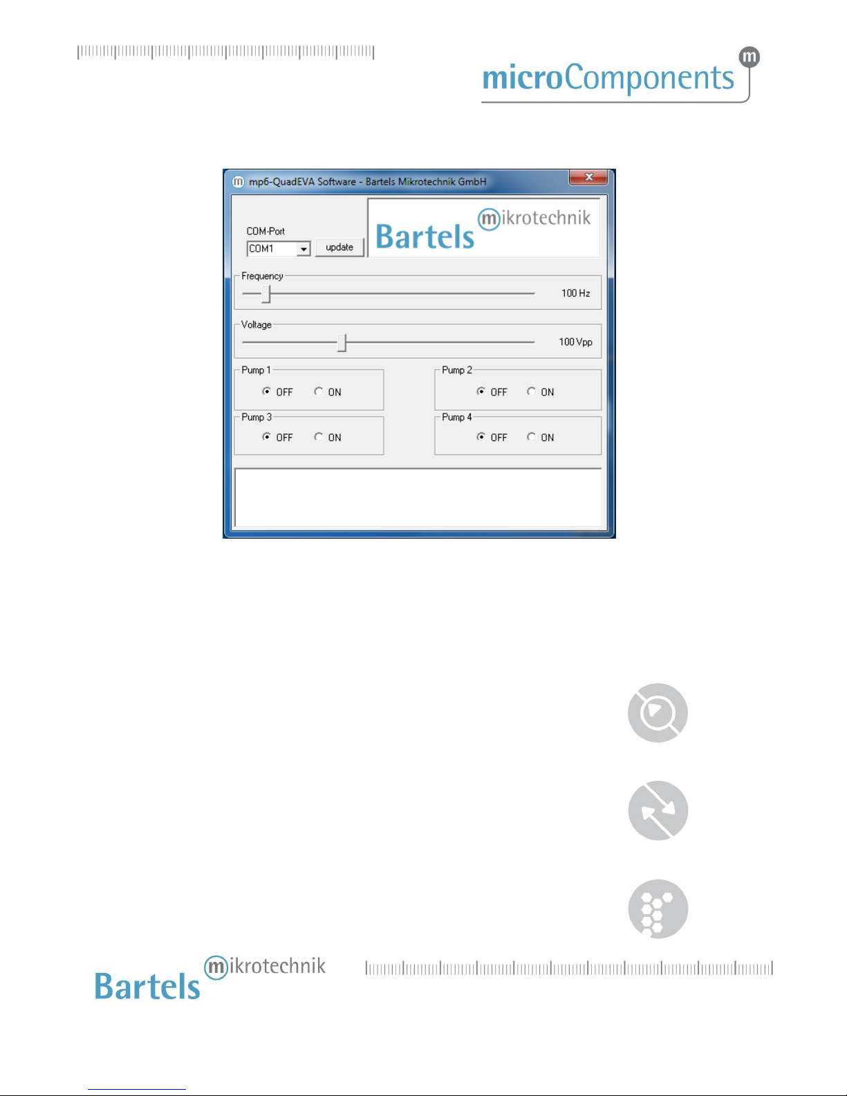
4.7 Software
Figure 5 Software window
Ensure that the board is connected to the PC and the driver is installed. After the software has started the
COM-port for the mp6-QuadEVA board has to be selected. If it is not present in the dropdown list please
verify that the board is correctly connected and press on “Update” to refresh the list.
The slider “Frequency” allows changing the pump frequency. The current frequency is displayed at the right
side.
The slider “Voltage” allows changing the pump voltage. The current voltage is displayed at the right side.
With the “OFF” and “ON” elements the individual pumps can be turned on and off.
All send commands and answers from the board are displayed in the text field at the bottom.

(03.2018) rev.4
12
Bartels Mikrotechnik GmbH, Konrad-Adenauer-Allee 11, 44263 Dortmund, Germany
www.bartels-mikrotechnik.de, info@bartels-mikrotechnik.de
Tel: +49-231-47730-500, Fax: +49-231-47730-501
5Maintenance
5.1 Cooling
The board may create some heat at the control chip when under continuous operation and at max
performance. It was successfully tested for the duration of one hour at 800 Hz, 250 V and four connected
pumps; no active cooling was applied.
However, it is recommended to take care of sufficient air flow to remove excess heat or consider installing
some active cooling on the board.
5.2 Exchanging the micropump
To connect the mp6/mp6-AIR/mp6-pp and Molex, refer to following three figures. Orientate both
components as indicated on the first picture, the mp6/mp6-pp facing downwards with its serial number
marking (!) and the Molex connector with the four small openings visible from above. Then insert the
mp6/mp6-pp flex into the Molex connector (Step1). Close the Molex connector to complete the
interconnection between both components (Step 2).
Step 1
Step 2
Step 3
Figure 6 Connecting and removing of micropumps from the connector
(03.2018) rev.4
13
Bartels Mikrotechnik GmbH, Konrad-Adenauer-Allee 11, 44263 Dortmund, Germany
www.bartels-mikrotechnik.de, info@bartels-mikrotechnik.de
Tel: +49-231-47730-500, Fax: +49-231-47730-501
6Dimensions
80 mm (3.15 in.)
Figure 7 Dimensions of the mp6-QuadEVA
Height over all:
16 mm (0.63 in.)
60 mm
(2.36 in.)
(03.2018) rev.4
14
Bartels Mikrotechnik GmbH, Konrad-Adenauer-Allee 11, 44263 Dortmund, Germany
www.bartels-mikrotechnik.de, info@bartels-mikrotechnik.de
Tel: +49-231-47730-500, Fax: +49-231-47730-501
7Technical data and Performance charts
mp6-QuadEVA
evaluation board
Order code: mp6-QuadEVA
The mp6-QuadEVA is an evaluation board that allows controlling up to four mp6
micropumps simultaneously with one setting and up to a frequency of 800 Hz.
It is possible to change pump voltage and pump frequency directly with the rotary control
elements at the board or via USB. Simple control software is provided with the board. Also
any terminal software can be used to remotely control frequency and amplitude or
enable/disable each of the four pumps.
Dimensions
80 x 60 x 16 mm
3.15 x 2.36 x 0.63 in.
Pumping media
liquids, gases
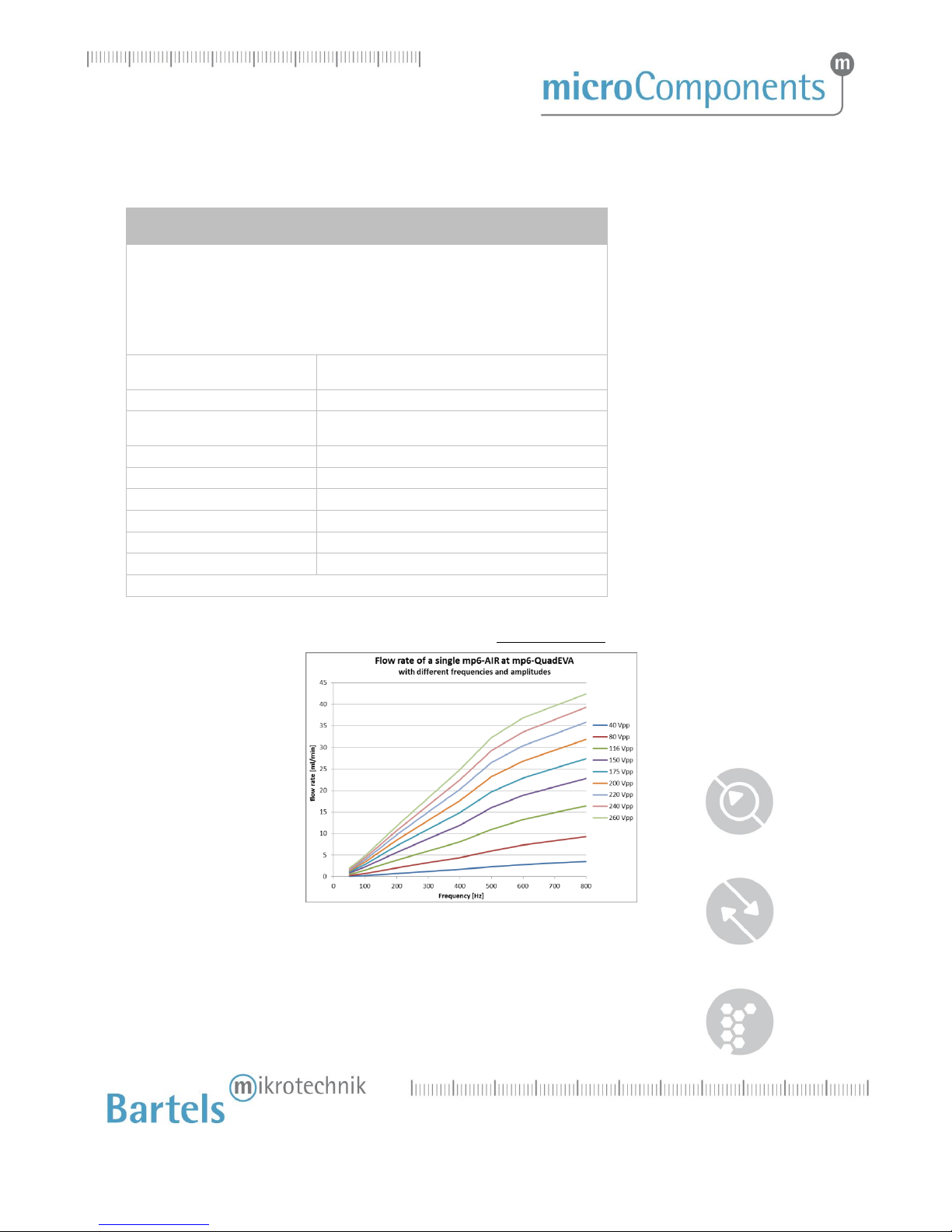
Max. volume flow
(mp6-AIR, gas: air)
each single mp6-AIR:
~42 ml/min @ 260 V; 800 Hz
Adjustable parameters
amplitude, frequency
Amplitude range
0 –260 Vpp
Frequency range
50 –800 Hz
Signal form
sine
Power supply
7.5 V, 1000 mA
Current consumption
avg. 220 mA, peak 280 mA1
1four connected mp6-AIR @ 260 V and 800 Hz
For pumping air, the flow rate and pressure generation of a single mp6-AIR is displayed below.
Figure 8 Flow rate of a single mp6-AIR attached to the mp6-QuadEVA

(03.2018) rev.4
15
Bartels Mikrotechnik GmbH, Konrad-Adenauer-Allee 11, 44263 Dortmund, Germany
www.bartels-mikrotechnik.de, info@bartels-mikrotechnik.de
Tel: +49-231-47730-500, Fax: +49-231-47730-501
Figure 9 Forward and Suction pressure of a single mp6-AIR attached to the mp6-QuadEVA
The forward pressure of serial connected mp6-AIR pumps is presented below with the left diagram. An
amplitude drop occurs at higher frequencies and/or with the higher load, i.e. connected pumps. This
behavior of the mp6-QuadEVA can be seen below in the right diagram.
Figure 10 Left diagram: Forward pressure of serial connected mp6-AIR pumps.
Right diagram: Amplitude drop behavior of mp6-QuadEVA.
8Serial solution
The mp6-QuadEVA was designed as an evaluation board and does not represent the right solution for serial
products. However, the circuit can be adapted for various applications.
On request we offer such a development for your customized solution. Additionally it is possible to order
the schematics, part list and source code for a licensing fee.

(03.2018) rev.4
16
Bartels Mikrotechnik GmbH, Konrad-Adenauer-Allee 11, 44263 Dortmund, Germany
www.bartels-mikrotechnik.de, info@bartels-mikrotechnik.de
Tel: +49-231-47730-500, Fax: +49-231-47730-501
Bartels Mikrotechnik GmbH
Konrad-Adenauer-Allee 11
44263 Dortmund Germany
www.bartels-mikrotechnik.de
info@bartels-mikrotechnik.de
For tutorials and further information
Visit our BLOG:
http://blog.bartels-mikrotechnik.de
Or our YouTube channel:
https://www.youtube.com/user/BartelsMikrotechnik
You can also find us here:
Facebook
Twitter
Xinq
Instagram
LinkedIN
Tel: +49-231-47730-500
Fax: +49-231-47730-501
Table of contents


