Servpro 613 User manual

Owner’s Manual
Revolution LGR Dehumidifier
#613 - 115V
MANUFACTURED BY DRI-EAZ PRODUCTS, INC. FOR SERVPRO INDUSTRIES, INC.
15180 Josh Wilson Road, Burlington, WA 98233
Phone: 800-932-3030 Fax: 360-757-7950 http://Revo.DriEaz.com
The Dri-Eaz®Revolution LGR Dehumidifier reduces humidity in enclosed environments by removing wa-
ter vapor from the air. The Revolution is ideal for water damage restoration, structural drying, construc-
tion, and many other applications requiring temporary, high-performance dehumidification.
Patents: http://www.LBpatents.com
READ AND SAVE THESE INSTRUCTIONS
Read and understand manual before operating.
WARNING! Do not alter or modify your Revolution in
any way. Use only replacement parts authorized by
Dri-Eaz Products, Inc. Modifications or use of unap-
proved parts could create a hazard and will void
your warranty. Contact your authorized Dri-Eaz dis-
tributor for assistance.
WARNING! Electric shock hazard, rotating fan, hot
surface hazards. Unplug unit before opening cover
for cleaning or servicing.
WARNING! Unit must be grounded.
•Keep motor and wiring dry. Keep out of standing wa-
ter and do not install in area likely to be subject to
water intrusion. Do not expose to rain, water or
snow.
•Insert three-prong plug on power cord into a match-
ing electrically grounded outlet. Do not use adapter.
Never cut off third prong.
•Do not use an extension cord.
•To reduce the risk of fire or electric shock, do not
use this unit with any solid-state speed control de-
vice.
FIRE HAZARD
•Keep away from open flames and heat sources.
•Do not use or store where vapors from gasoline, sol-
vents, thinners or other flammable materials may be
present.
WARNING! Unplug unit before cleaning or servicing.
•Turn off unit and unplug before lifting or moving.
•Handle the unit carefully. Always operate the unit on
a stable, level surface. Do not drop, throw, or place
where it could fall. Rough treatment can damage the
unit, and may create a hazardous condition or void
the warranty.
•Inspect the power cord before use. If cord is dam-
aged, do not use. Always grasp the plug (not the
cord) to unplug.
•The unit must be operated on a 115V/60 Hz circuit
protected by a Ground Fault Circuit Interrupter
(GFCI) device.
•Do not attempt to repair the unit. For authorized ser-
vice options, contact SERVPRO®RMA Department
at 866-885-6833 or email rma@servpronet.com.
BEFORE YOU BEGIN
Warranty registration
To process a warranty or repair claim, just click the
“RMA/ Warranty Form” listed under the “Products” tab
on the ServproNET®home page or it is also found at the
Equipment page on ServproNET.
You may contact the SERVPRO®RMA Department by
phone at 866-885-6833 or via email at
rma@servpronet.com.
To expedite the warranty claim process, please have the
following:
•Equipment model number.
•Serial number.
•Usage hours (if applicable).
When Franchises purchase equipment from Servpro
Industries, Inc., unit date of purchase and serial numbers
are recorded on the invoice. As part of the Servpro In-
WARNING
07-01897D #613 (F413-SP) Warranty 07-00420 1 Dri-Eaz Products, Inc.

dustries, Inc. RMA/Warranty program, proof of purchase
and equipment warranty records are added to the data-
base. This service saves Franchisees time and re-
sources spent attempting to determine warranty cover-
age for equipment.
After receipt of the completed Warranty/RMA Request
Form, an RMA Coordinator will check warranty status on
any listed equipment prior to submitting the claim infor-
mation to the vendor(s).
If the unit is covered under warranty, the RMA Coordina-
tor will communicate the repair and return process.
If equipment is not covered under warranty, the ven-
dor(s) will provide a competitive repair estimate prior to
completing any non-warranty repairs. The RMA Coordi-
nator will present repair options and receive Franchise
approval prior to authorizing non-warranty repairs.
The SERVPRO RMA Department is here to serve you!
INTRODUCTION
NOTICE: Some assembly required before use. Follow
instructions under “Controls and Operating Instructions,”
left.
The Revolution Dehumidifier reduces humidity in en-
closed structural environments by removing water vapor
from the air. With proper use, the Revolution can help to
dry out damp structural materials, insulation, and con-
tents, and maintain a healthy level of humidity. Using the
Revolution may also prevent secondary damage caused
by high humidity.
How the Revolution works
The Revolution refrigerant dehumidifier uses a fan to
draw moist air in and condenses it into water that col-
lects in a tray and is automatically pumped out through a
drain hose. The unit can be set to operate continuously
or the user may select Humidistat Mode. In Humidistat
Mode, the Revolution will turn on and off automatically to
maintain the inlet humidity level the user has selected.
Features:
•Industrial-quality dehumidifier removes up to 134
pints (63 liters) of water per day.
•Automatic humidistat to set and maintain desired
humidity level.
•Recessed feet indents ensure secure stacking of up
to three Revolution units for storage and transport.
•Designed for convenient stacking and transporting
on a handtruck.
•Recessed handles for easy positioning in confined
spaces.
•Quiet operation and low power consumption.
CONTROLS AND OPERATING IN-
STRUCTIONS
Set unit upright
NOTICE: Always store, transport, and use the unit in
a horizontal position. If the unit is ever placed in a
vertical position, return it to the horizontal position
and let it stand for at least 30 minutes before turning
it on.
Positioning a Dehumidifier
For best results, operate your dehumidifiers in an en-
closed area. Close all doors and windows that open to
the outside to maximize water removal efficiency. Place
your dehumidifier away from obstructions, and keep it
away from anything that could block airflow into and out
of the unit. For more information about creating an opti-
mum drying environment, contact Dri-Eaz at
800-932-3030.
Set up drain hose
The Revolution condensate pump connects to a plastic
drainage hose. This hose is equipped with a quick-
connect fitting for quick attachment to the provided 40 ft.
(12 m) drain hose. Unwrap the entire hose and place the
unattached end in a sink, drain, bucket or outdoors –
anywhere that water can drain out safely. If you use a
bucket or other container for water collection, check it
regularly to prevent overflows.
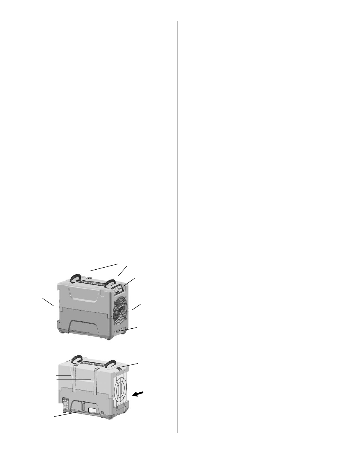
Carry handles
Fig. A: Parts Identification
Condensate
drain quick-
connect
Air inlet
Control
panel
Remove/Insert
air filter here.
Air outlet
Power
socket
Cord and
hose storage
wraps.
Temp/RH
sensor
07-01897D #613 (F413-SP) Warranty 07-00420 2 Dri-Eaz Products, Inc.
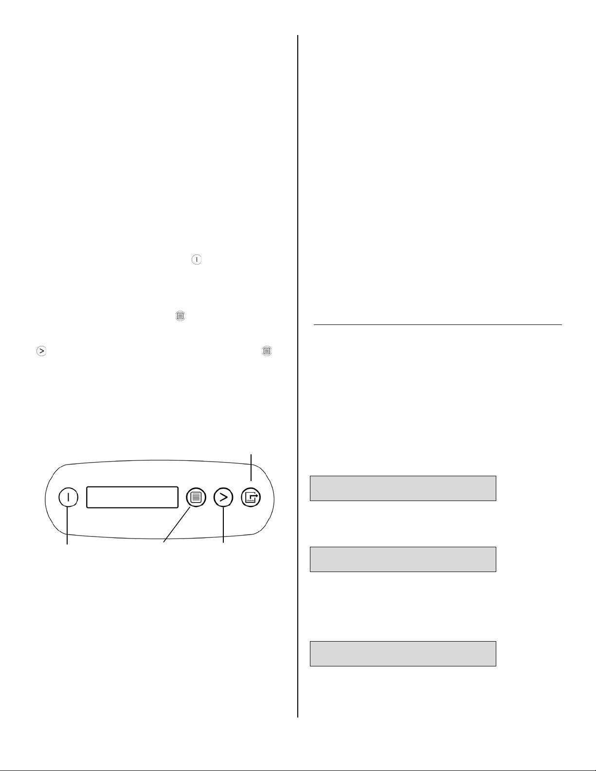
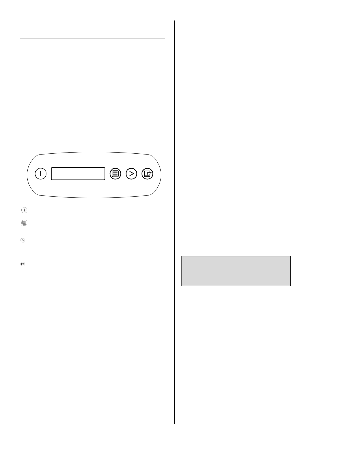
CONTROL PANEL
ON/OFF
DISPLAY
DISPLAY
MENU
MENU SE-
LECTION /
UP KEY
PURGE PUMP
NOTICE: Uncoil and straighten the entire drain hose. Do
not leave any part of the hose coiled and do not place
the end of the hose higher than 20 ft. (6 m) above the
bottom of the unit. Also check for kinks or other obstruc-
tions that might restrict the flow of water. Obstructions
may cause a water backup and result in overflows.
Plug in electrical cord
The Revolution should be plugged into a GFCI-protected
115 volt outlet rated for at least 15amps. Always plug
the cord firmly into the unit first, and then plug the other
end into a suitable outlet.
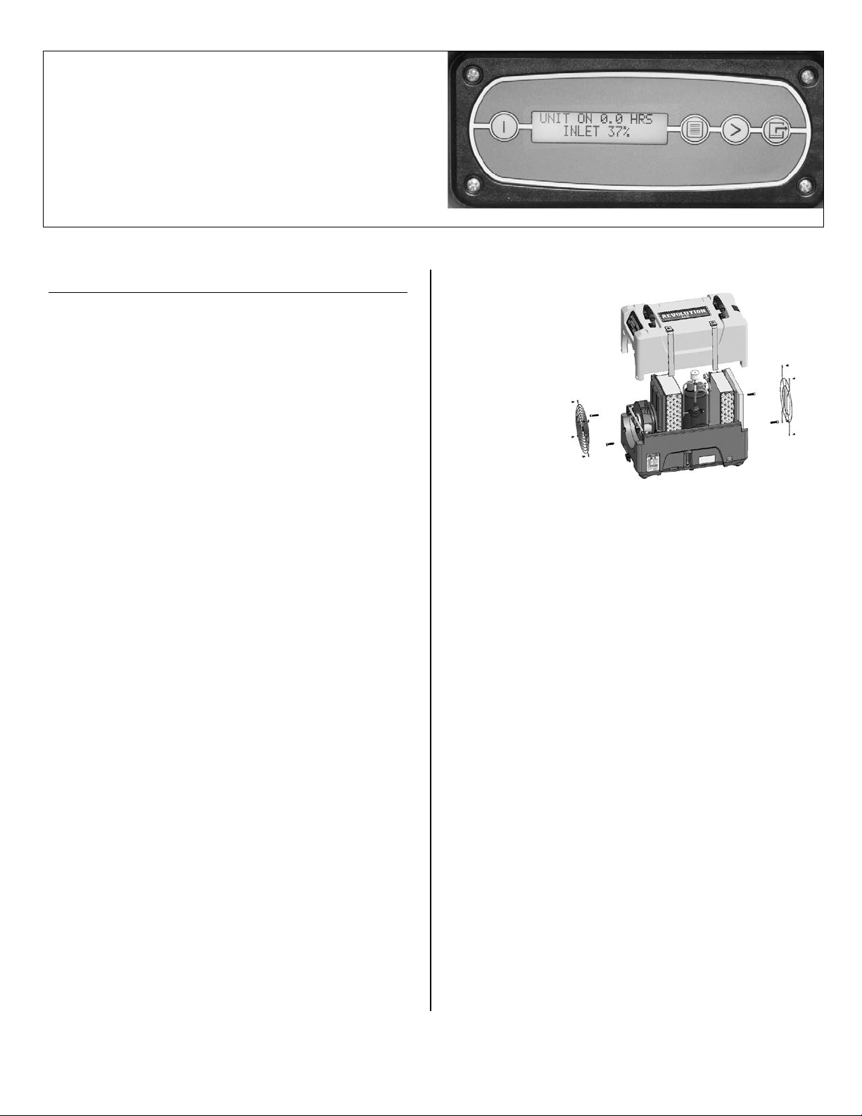
Startup display and normal display modes
When unit is first plugged in to AC power, the control
panel display will briefly cycle through a series of
readouts. This is part of the unit’s self-diagnosis proce-
dure and no user intervention is required.
To turn the unit on, press ON/OFF.
User Settings Menu
A number of display settings may be changed by the
user. System information can also be displayed. These
items are accessed by pressing DISPLAY MENU.
Each press of the key will display the next parameter.
When you reach the parameter you wish to adjust, press
MENU SELECTION to increase the value. Press
DISPLAY MENU again to accept the setting and re-start
the display cycle. If no keys are selected for 5 minutes
the display will automatically reset and return to the
normal display mode.
Note that only menu items followed by a greater-than
symbol (>) may be adjusted.
All settings and modes are discussed in detail in Control
Panel Guide, beginning on p. 5.
Error messages
If the Revolution onboard diagnostics discover a prob-
lem, the unit will display an error message. See “System
Messages,” p. 11 for an explanation of each message.
TRANSPORTATION AND STORAGE
NOTICE: Handle the unit carefully. Do not drop, throw,
or place the unit where it could fall. Rough treatment can
damage this equipment and may create a hazardous
condition or void warranty.
•Do not expose the control panel to moisture, snow
or rain.
•Protect from freezing.
•Store and transport securely to avoid any damaging
impact to internal parts.
•Secure during transport to prevent sliding and pos-
sible injury to vehicle occupants.
AT THE END OF THE JOB
To reduce the possibility of drips when moving the unit,
follow these additional steps to ensure that all water is
removed from the unit.
NOTICE: To ensure the condensate tank empties com-
pletely while purging, make sure the unit is positioned
horizontally on a flat surface.
1. If the unit is in a defrost cycle, wait until the unit has
returned to normal operating mode before proceeding.
To check, review the control panel. The control panel will
show one of the following:
Defrost in progress:
UNIT ON 00 HRS
DEFROST XX
Display mode when unit is in defrost mode. XX indicates
the minutes remaining on the defrost cycle.
Shutdown Sequence
WAIT FOR
DEFROST XX
Display mode when unit is in defrost and is powered
down by the user. Unit will complete the defrost cycle to
remove any built-up ice and then purge the pump. XX
indicates the minutes remaining on the defrost cycle.
Normal Display:
UNIT ON 00 HRS
INLET XX° F
Wait until the control shows the normal display before
proceeding.
2. Gently rock the machine to ensure any water remain-
ing on interior surfaces falls into the sump area.
ON/OFF
Press and release to turn unit on
or off.
DISPLAY MENU
Press to select next item in menu.
Menu item will show in display.
MENU SELECTION /
UP KEY
Press to toggle or select values in
menu displayed.
PURGE PUMP
Press and release to start purge.
Display will count down seconds
remaining until purge is complete.
07-01897D #613 (F413-SP) Warranty 07-00420 3 Dri-Eaz Products, Inc.

3. Press the PURGE key. When the purge cycle is
complete, turn the unit off.
4. Remove the external drain hose, drain it carefully, coil
it and secure it with one of the Velcro straps provided on
the side of the unit.
5. Unplug power cord from power supply and from base
of the machine, coil neatly, coil it and secure it with one
of the Velcro straps provided on the side of the unit. (see
Fig. A).
07-01897D #613 (F413-SP) Warranty 07-00420 4 Dri-Eaz Products, Inc.
CONTROL PANEL GUIDE
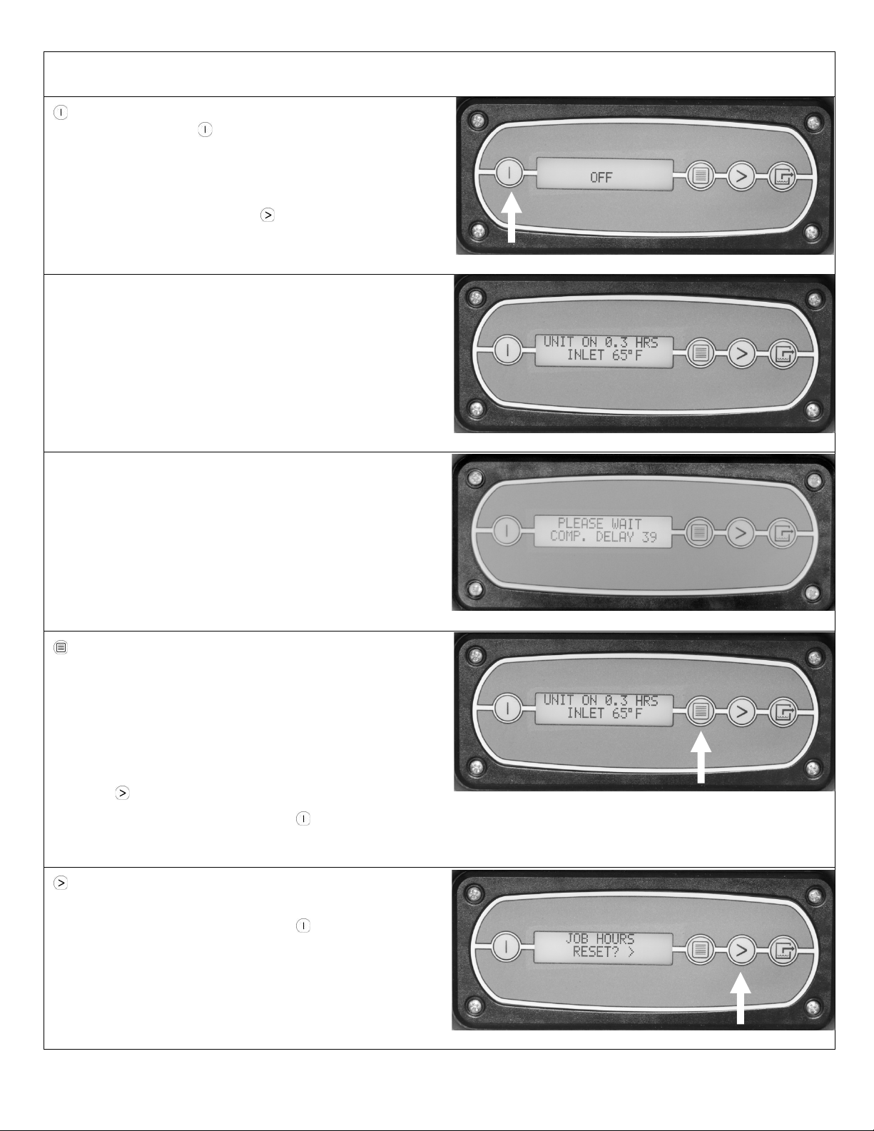
Button Functions
ON/OFF. After plugging in the unit, the display will show
the word “OFF”. Press ON/OFF to turn the unit on.
When the machine is turned on, the display normally reads
NOTE: If the unit was previously unplugged or otherwise
lost power prior to turning the unit off, the display will show
OFF / POWER FAILURE. Press MENU SELECTION to
clear this message.
Note that the second line of the display cycles between
inlet temperatures and %RH values.
In some conditions the unit will perform a numeral count-
down when you first plug it it. The countdown will range up
to maximum of 60 seconds, and will count down to zero
before starting the compressor. Do not press any buttons
until the unit has completed the delay countdown and dis-
plays the “Unit On” message shown above. NOTE: If no
compressor delay countdown is displayed, a delay is not
necessary and the machine will begin operation immediate-
ly.
DISPLAY MENU. Press repeatedly to cycle through the
display of additional dehumidifier conditions and user de-
fined settings. This includes JOB HOURS>, INLET OUT-
LET, HUMIDISTAT MODE>, HUMIDISTAT SETPOINT>,
TEMP UNITS>, LANGUAGE>, COIL TEMP, SENSOR ID>
(this function is not used in the Revolution), and
COMPRSSR CURRENT.
Menu items marked by a caret (>) may be set by the users
using the MENU SELECTION key. See below.
To return to the main menu, press the ON/OFF key
once.
MENU SELECTION. Press to change the values of any
of the User Defined Menu items displayed with a caret (>).
To return to the main menu, press the ON/OFF key
once.
See User Settings Menu (below) for details.
07-01897D #613 (F413-SP) Warranty 07-00420 5 Dri-Eaz Products, Inc.

PURGE. Press to empty water from the condensate
pump reservoir. The display will read PUMP PURGING
with a numeral countdown. NOTE: During normal opera-
tion, the pump purges automatically every ten minutes for
25 seconds, or whenever the reservoir is full.
The PURGE function may be used at any time the unit is
connected to AC power.
User Defined Menu Items
The first line of the display shows the total number of hours
the unit has been in operation. This value may be reset to
zero to track job hours (see “Job Hours Reset” below). The
second line of the display alternates between inlet tem-
perature and inlet RH.
Note: If no keys are selected for 20 seconds the display will
automatically reset and return to the normal display mode.
To move to the next item in the menu, press DISPLAY
MENU.
To reset job hours to zero, press MENU SELECTON.
To move to the next item in the menu, press
DISPLAY MENU.
The display shows total unit operating hours. This value
cannot be reset.
To move to the next item in the menu, press
DISPLAY MENU.
07-01897D #613 (F413-SP) Warranty 07-00420 6 Dri-Eaz Products, Inc.
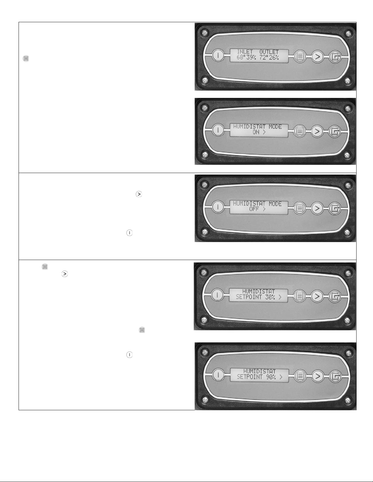
The display shows the current temperature and RH of inlet
and outlet. This item may not be reset.
To move to the next item in the menu, press
DISPLAY MENU.
HUMIDISTAT MODE
To turn the humidistat mode ON, press MENU
SELECTON. The unit will maintain the humidistat setpoint.
To change the setpoint, see the next frame below.
To return to the main menu, press the ON/OFF key
once.
Press DISPLAY MENU to see the current setpoint.
Each press of MENU SELECTON increases the
setpoint by 5% increments, cycling through 90%RH and
starting again at 30%RH.
When the desired setpoint is shown, press DISPLAY
MENU to set and move to the next menu item.
To return to the main menu, press the ON/OFF key
once.
07-01897D #613 (F413-SP) Warranty 07-00420 7 Dri-Eaz Products, Inc.
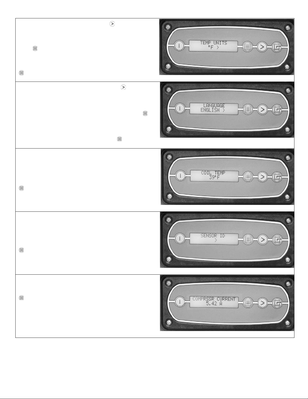
Shows current temperature scale. Press MENU
SELECTON to select Fahrenheit or Centigrade scale.
When the temperature scale you wish to use is displayed,
press DISPLAY MENU to select it and move to the next
menu item.
To move to the next item in the menu, press
DISPLAY MENU.
Shows current display panel language. Press MENU
SELECTON to select Spanish, German, French or Eng-
lish.
When the language you wish to use is displayed, press
DISPLAY MENU to select it and move to the next menu
item.
To move to the next item in the menu press DISPLAY
MENU.
Shows the current cold (evaporator) coil temperature in
the selected temperature scale. This value cannot be
changed.
To move to the next item in the menu, press
DISPLAY MENU.
The SENSOR ID menu item and associated submenus
(SENSOR TYPE, SENSOR CFG REV, and SENSOR
REV) are not used in the Revolution.
To move to the next item in the menu, press
DISPLAY MENU.
Shows compressor current draw in amps.
To move to the next item in the menu, press
DISPLAY MENU.
07-01897D #613 (F413-SP) Warranty 07-00420 8 Dri-Eaz Products, Inc.
You have now reached the end of the User Setting Menu.
The unit will now show the default display.
NOTE: When in Humidistat mode, the unit will display HU-
MIDISTAT on the top line during normal operation rather
than UNIT ON 0.0 HOURS.
MAINTENANCE SCHEDULE
Refer to the SERVPRO Operations and Maintenance
Guide for helpful pictures and detailed instructions.
WARNING! ELECTRIC SHOCK HAZARD. Unplug unit
before cleaning or servicing.
WARNING: Risk of dust and contaminants exposure.
Use of respirator mask and gloves is recommended. If
unit has been exposed to potentially dangerous contam-
inants, clean thoroughly and sanitize before reuse.
NOTICE: The unit is fitted with sensitive electronic sen-
sors. Protect the sensors and their lead wires from dam-
age and do not expose them to water or cleaning solu-
tion.
The following tools and supplies are needed to
complete the maintenance procedures described in
this manual:
Philips screwdriver
10 mm wrench
6 mm hex bit
¼ in. nut driver
Cleaning cloths
HEPA vacuum cleaner with soft brush nozzle and
crevice nozzle.
Recommended
Cordless drill, small knife, small-jaw pliers, coil clean-
ing solution, rotomolded housing cleaning solution.
For your convenience, a Dehumidifier
Maintenance Checklist is provided on p. 13.
Before each use
Inspect the electrical cord for damage. Look for fray-
ing, cuts, etc. Replace the cord if you find any damage.
Inspect, vacuum or replace filter. The Revolution is
provided with a 3M™ HAF High Air Flow filter (part no.
F372). HAF filters may be vacuumed clean and re-
used up to three times before replacement. Use a
HEPA vacuum and brush tool to remove any dust or de-
bris. Do not use compressed air or expose the filter to
any liquids, as may damage the filter.
Monthly
Inspect coils. Clean when dust accumulation is visible.
In normal use, dust can accumulate and can restrict air-
flow, reducing performance and causing the unit to over-
heat. Use a vacuum cleaner with a brush tool and a soft
cloth to remove any debris. Take care not to damage
any interior components.
To maintain appearance, wipe interior and exterior sur-
faces with a damp cloth. For deep cleaning and a last-
ing, protective shine, use an automotive interior cleaner.
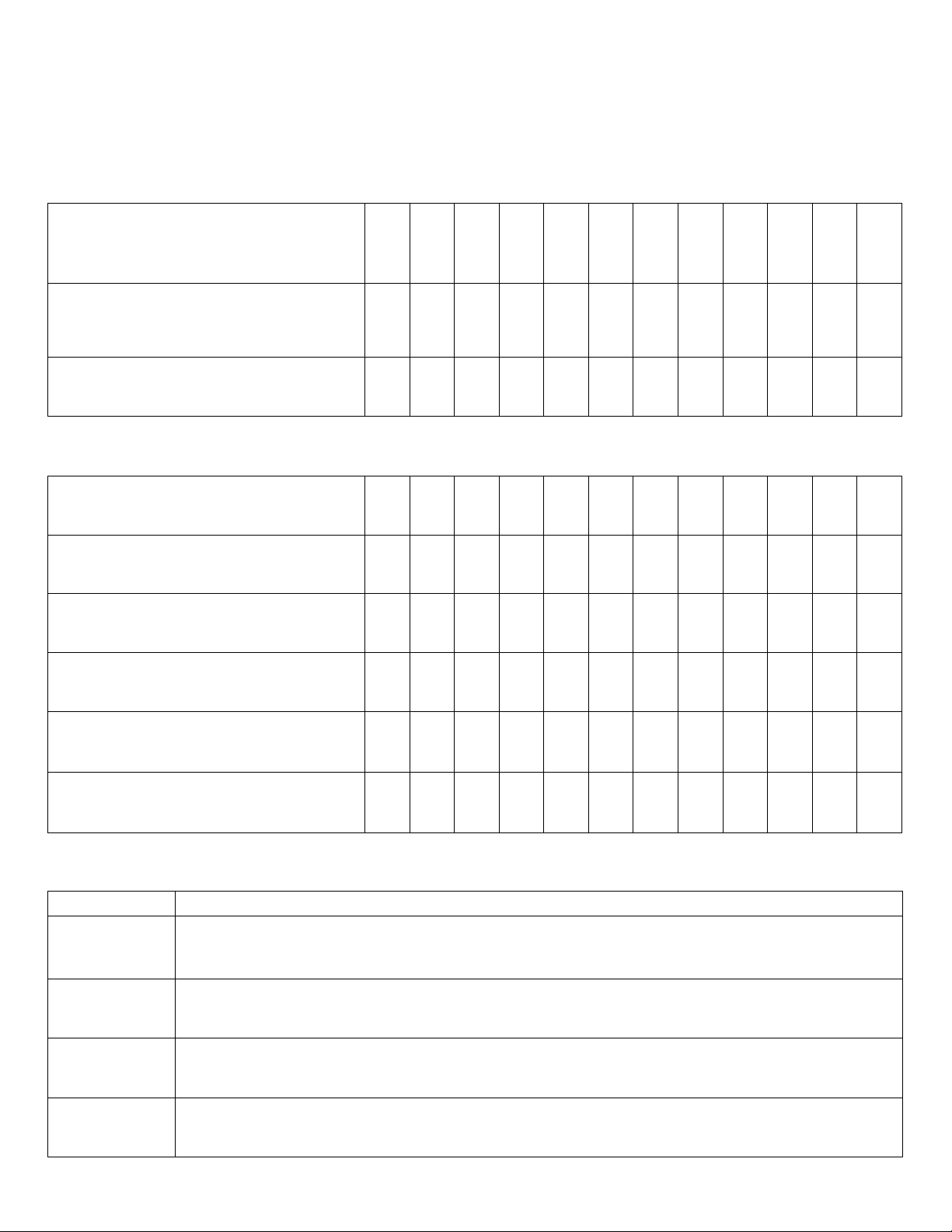
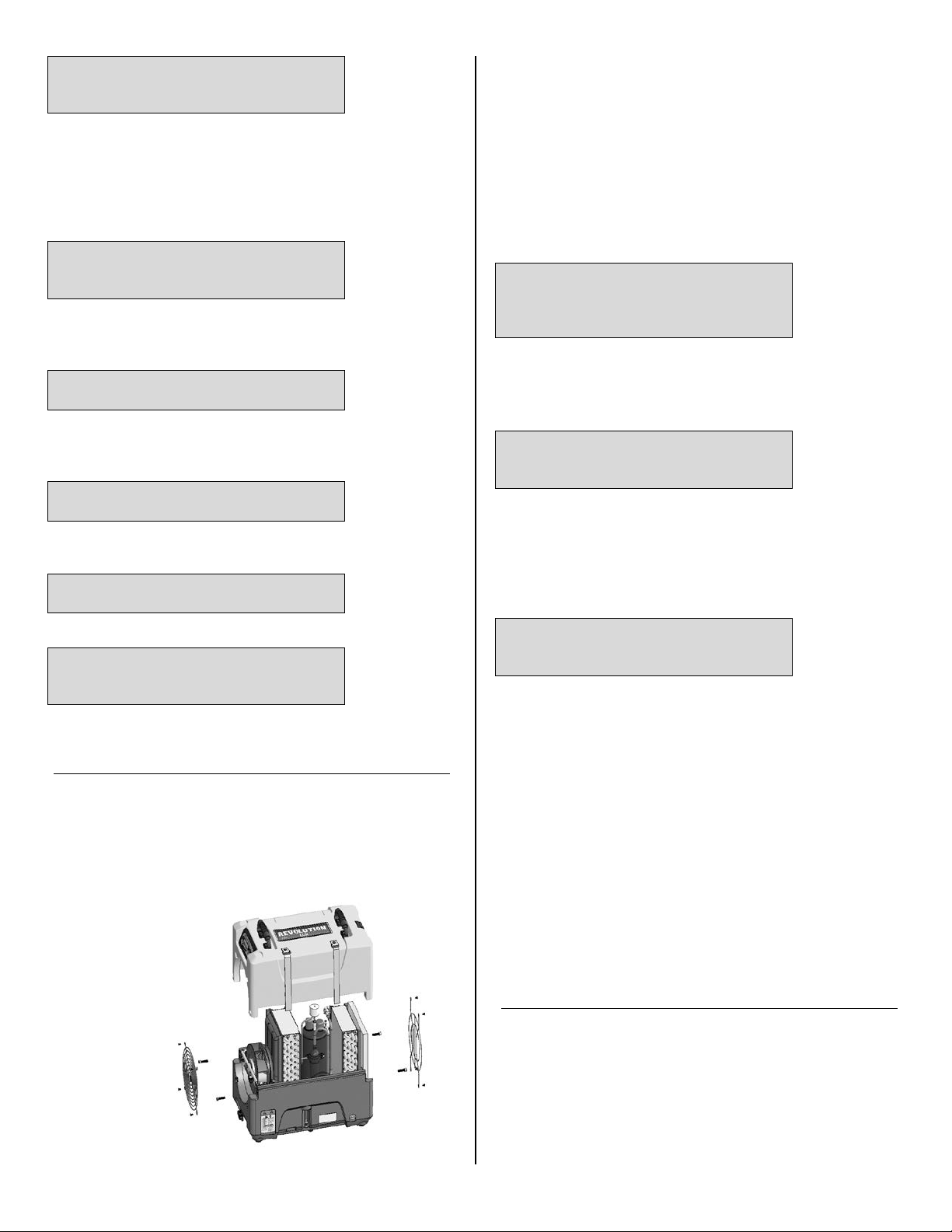
Remove the 4 screws
from housing and 2
top screws each from
inlet and outlet grills
and lift off cover.
Fig. B: Disassembly for Cleaning
07-01897D #613 (F413-SP) Warranty 07-00420 9 Dri-Eaz Products, Inc.

As Needed
Clean pump check valve and basin. If the unit displays
the message “ER9 PUMP BLOCKED CHECK PUMP &
HOSE”, the pump check valve and pump basin may
need to be cleaned. Remove grills and cover as shown
in Fig. B. Remove screws from pump base and lift out
pump. Wipe out pump basin with a damp cloth. Inspect
the pump base for build-up of debris and clean if need-
ed. Unthread barbed fitting with check valve and rinse
fitting and check valve with clean water. Reinstall check
valve into barbed fitting and install the barbed fitting into
pump. Do not overtighten. Reinstall pump on base. Re-
install cover and grills. Clean coils. With the cover re-
moved, inspect both coils. If excessive dust and debris is
present, vacuum thoroughly and/or clean with coil clean-
er.
ABOUT 3M™ HIGH AIR FLOW FILTERS
HAF filters from 3M provide superior particle retention, resist microbial growth on filter surfaces and allow for maximum
airflow throughout the filter loading cycle. Follow these guidelines to ensure maximum protection for equipment, techni-
cians and the job site:
Replace the HAF filter whenever it has been vacuumed clean and reused three times. HAF filters lose their effectiveness after
three uses.
Replace the HAF filter whenever it has been used on a mold remediation job or otherwise exposed to potentially dangerous
contaminants. Continued use of a contaminated filter risks the spread of contamination.
Do not wash or apply any liquids to the HAF filter. Exposure to liquids will reduce the effectiveness of the electrostatic material.
Do not operate without the HAF filter in place. Do not operate the unit with any other filter type. Incorrect filtration will reduce
unit efficiency and can cause damage to the unit.
07-01897D #613 (F413-SP) Warranty 07-00420 10 Dri-Eaz Products, Inc.

System messages
The Revolution control system constantly monitors internal operating conditions. If the system detects a problem, it will
produce an error (“ER”) message. If the display shows an ER message, first unplug the unit and then plug it back in. This
will usually reset the electronics, and the unit will begin operating normally. If the error message reappears, refer to the
explanation and solution shown below. If this still does not fix the problem, contact your local authorized service center or
call the Dri-Eaz Service Department at 800-932-3030.
NOTE: The message “POWER FAILURE” is not a system error. When this message is displayed, it indicates that
power to unit was interrupted and then restored. To clear the message, press the MENU SELECTION key.
CONTROL PANEL
MESSAGE EXPLANATION AND SOLUTION
ER1 CONTACT SERVICE
CENTER
Voltage error. Confirm that unit is connected to a suitable AC power supply and that the
circuit is not overloaded. If supply is correct, the electronic control panel may require
replacement. If error persists, contact service.
ER2 CONTACT SERVICE
CENTER Control panel error. The electronic control panel may require replacement. If error per-
sists, contact service.
ER3 CONTACT SERVICE
CENTER Unit in defrost too long. Check defrost sensor cable for proper connection. If error per-
sists, sensor assembly may require replacement. Contact service.
ER4 √ DEFROST SENSOR
CONNECT
– alternate message –
ER4 √ OUTLET SENSOR
CONNECT
Sensor error. Check defrost sensor cable for proper connection. If error persists, sensor
assembly may require replacement. Contact service.
ER5 √ SENSOR
CONNECTION ON BD Check inlet Temp/RH sensor for proper connection. If error persists, contact service.
ER6 CONTACT
SERVICE CENTER High voltage error. The high voltage board may require replacement. If error persists,
contact service.
ER7 INVALID
MODEL SETTING Control board DIP switch settings or firmware version may be incorrect. If error persists,
contact service. Service may ask you to verify DIP switch settings.
ER8 BUTTON STUCK √
ALL BUTTONS Press each membrane key and check for proper operation. If a key doesn’t function, or
if the error persists, the membrane overlay may require replacement. Contact service.
ER9 PUMP BLOCKED √
CHECK PUMP & HOSE
Check for obstructions in drain hose. If clogged, remove hose from unit and blow hose
out with compressed air. Inspect and clean the pump check valve and pump basin. See
“Clean pump check valve and basin,” p. 10.
07-01897D #613 (F413-SP) Warranty 07-00420 11 Dri-Eaz Products, Inc.

TROUBLESHOOTING
FAULT CAUSE SOLUTION
Water drips out
when moving unit Unit was unplugged before
purging was complete.
Purge unit before moving. See PURGE in Control Panel in-
structions, p. 6. At the end of the job, see “At the End of the
Job,” p. 3.
Unit does not
operate Unit not switched on.
No power to machine.
Switch unit on.
Plug in unit; check power cord connection at wall outlet and at
base of unit.
Unit operating,
but room not dry
Not enough time to dry.
Poor air movement in room.
Excessive moist air infiltration.
Allow more time for drying.
Increase air movement with air movers.
Seal off area to reduce infiltration.
Unit collects too
little water
Room air is dry.
Room temperature is too low.
Filter is clogged.
Coils are clogged.
Confirm humidity level with hygrometer.
Increase room temperature.
Check filter. Clean or replace as necessary.
Check coils. Clean as necessary.
If the problem you are experiencing is not listed here, call your local distributor or contact
our Service Department toll-free at 800-932-3030 for further assistance.
SPECIFICATIONS
Name Revolution LGR Dehumidifier
Model F413-115V
Dimensions (W × H × D) 12.5 × 17.6 × 21.5 in.
31.8 × 44.7 × 130.8 cm
Weight (w/ cord & hose) 65 lbs. | 29.5 kg
Amps 6.2 amps at 80°F/60% RH
Power
115V / 60Hz
Air movement 121–180 CFM | 3.43–5.1 CMM
Water removal
80 pts/day | 38 L/day
at 80°F/60% RH (AHAM)
134 pts/day | 63 L/day
at 90°F/90% RH
Operating temperature range 33–100°F |1–38°C
Safety ETL certified to CSA Standards
Specifications are subject to change without notice. Some values
may be approximate.
PARTS INCLUDED
40 ft. (12 m) of drain hose with quick-connect fitting.
25 ft. (7.6 m) detachable power cord.
3M™ HAF High Air Flow filter
OPTIONAL
Duct Attachment Kit (F530)
FILTERS FOR REORDER
3M™ HAF High Air Flow filter F372 (24 pack)
ADDITIONAL PRODUCT INFORMATION and current
documentation is available at http://Revo.DriEaz.com.
FOR PARTS AND SERVICE CONTACT SERVPRO
RMA DEPARTMENT.
07-01897D #613 (F413-SP) Warranty 07-00420 12 Dri-Eaz Products, Inc.
Dehumidifier Maintenance Checklist
Use this checklist to monitor the maintenance of your Dri-Eaz dehumidifiers. As each task is completed, note the date
and the operator’s initials in the boxes provided. Regular maintenance will keep your equipment operating at maximum
efficiency.
BEFORE EACH USE
Inspect the electrical cord for damage.
Look for fraying, cuts, etc. Replace dam-
aged cords before using the unit.
Inspect filter. Look for accumulated dust
and dirt that would restrict airflow. Vacuum
out any debris.
Check drain hose for obstructions. Clear
any debris present.
IMPORTANT: HAF filters may be vacuumed and reused up to three times before replacement. Filters should be replaced after every mold job.
MONTHLY
Inspect coils and heat exchange block.
Clean when visibly dirty.
Check pump basin and drip tray. Clean
when dirt and debris are present.
Inspect and clean pump check valve.
Clean exterior housing to maintain profes-
sional appearance.
Inspect impeller, duct ring and grill for
damage and/or debris and clean/replace if
required.
Inspect control panel. Toggle through dis-
play screens to ensure that the unit is func-
tioning properly.
NOTES:
Note any other maintenance tasks completed, and record any damage or operational problems that may need attention.
Date
Note
07-01897D #613 (F413-SP) Warranty 07-00420 13 Dri-Eaz Products, Inc.
Manual de instrucciones
Deshumidificador Revolution LGR
#613 - 115V
MANUFACTURED BY DRI-EAZ PRODUCTS, INC. FOR SERVPRO INDUSTRIES, INC.
15180 Josh Wilson Road, Burlington, WA 98233
Teléfono: 800-932-3030 Fax: 360-757-7950 http://Revo.DriEaz.com
El deshumidificador Dri-Eaz®Revolution LGR reduce la humedad en ambientes cerrados al eliminar el
vapor de agua del aire. El Revolution es ideal para la restauración de daños ocasionados por el agua, el
secado estructural, la construcción y muchas otras aplicaciones que requieren deshumidificación tempo-
ral de alto rendimiento.
Patentes: http://www.LBpatents.com
LEA Y GUARDE ESTAS INSTRUCCIONES
Lea y entienda el manual antes de operar el des-
humidificador.
¡ADVERTENCIA! No altere ni modifique su deshumi-
dificador Revolution de ninguna forma. Utilice sola-
mente las piezas de repuesto autorizadas por Dri-
Eaz Products, Inc. Las modificaciones o el uso de
piezas no autorizadas podrían generar riesgos y
anular la garantía. Póngase en contacto con su dis-
tribuidor Dri-Eaz autorizado para obtener ayuda.
¡ADVERTENCIA! Peligro de choque eléctrico, venti-
lador giratorio, riesgos por superficies calientes.
Desconecte la unidad antes de abrir la cubierta para
limpiarla o darle mantenimiento.
¡ADVERTENCIA! La unidad debe estar conectada a
tierra.
•Mantenga el motor y el cableado secos. Mantenga
la unidad lejos del agua estancada y no la instale en
zonas que puedan verse sometidas a entrada de
agua. No exponga el deshumidificador a la lluvia,
agua o nieve.
•Inserte el contacto de tres clavijas del cable de ali-
mentación a un tomacorriente conectado a tierra.
No use un adaptador. Nunca corte la tercera clavija.
•No utilice un cable de extensión.
•Para reducir el riesgo de incendio o descarga eléc-
trica, no use esta unidad con un dispositivo de con-
trol de velocidad de estado sólido.
PELIGRO DE INCENDIO
•Mantenga la unidad apartada de flamas abiertas y
fuentes de calor.
•No la utilice ni la almacene donde haya vapores de
gasolina, solventes, diluyentes u otros materiales in-
flamables.
¡ADVERTENCIA! Desconecte la unidad antes de lim-
piarla o darle mantenimiento.
•Apague la unidad y desconéctela antes de levantar-
la o moverla.
•Maneje la unidad con cuidado. Opere siempre la
unidad sobre una superficie estable y nivelada. No
la deje caer, no la tire ni la coloque donde pueda
caerse. Un trato brusco puede dañar la unidad y
puede generar una condición peligrosa o anular la
garantía.
•Inspeccione el cable de alimentación antes de utili-
zar la unidad. Si el cable está dañado, no utilice la
unidad. Sujete siempre la clavija (no el cable) para
desconectarla.
•La unidad debe operarse en un circuito de 115V/60
Hz protegido por un dispositivo interruptor de circui-
to por falla en tierra (GFCI, por sus siglas en inglés).
•No intente reparar la unidad. Para conocer las op-
ciones de servicio autorizadas, comuníquese con el
Departamento de RMA de SERVPRO®, al 866-885-
6833, o por correo electrónico a
rma@servpronet.com.
ADVERTENCIA
07-01897D #613 (F413-SP) Warranty 07-00420 14 Dri-Eaz Products, Inc.
ANTES DE COMENZAR
Registro de la garantía
Para tramitar una reclamación con base en la garantía o
solicitar una reparación, simplemente haga clic en el
‟Formulario de la garantía/RMA” (RMA/ Warranty Form),
que se encuentra en la pestaña de ‟Productos” (Pro-
ducts), de la página de inicio de ServproNET®, o en la
página de Equipo (Equipment) de ServproNET.
Para comunicarse con el Departamento de autorización
de devolución de mercancía (RMA, por sus siglas en
inglés) de SERVPRO®, llame al 866-885-6833 o escriba
un correo electrónico a rma@servpronet.com.
Para acelerar el proceso de reclamación con base en la
garantía, tenga a la mano la siguiente información:
•Número de modelo del equipo.
•Número de serie.
•Horas de uso (en su caso).
Cuando una franquicia compra equipo de Servpro Indus-
tries, Inc., en la factura se incluye la fecha de compra de
la unidad y los números de serie. Como parte del pro-
grama de garantía/RMA de Servpro Industries, Inc., en
la base de datos se agrega el comprobante de la com-
pra y el expediente de la garantía del equipo. Este servi-
cio les ahorra a las franquicias el tiempo y el dinero que
perderían tratando de determinar la cobertura de la ga-
rantía del equipo.
Después de recibir el formulario de solicitud de garant-
ía/RMA completo, un Coordinador de RMA comprobará
el estado de la garantía de cualquier equipo antes de
presentar la información de la reclamación al(los) pro-
veedor(es).
Si la unidad está cubierta por la garantía, el Coordinador
de RMA explicará el proceso de reparación y devolu-
ción.
Si la garantía no cubre el equipo, el(los) proveedor(es)
proporcionará(n) un presupuesto de reparación que re-
sulte atractivo antes de realizar cualquier reparación que
no esté incluida en la garantía. Antes de autorizar las
reparaciones que no estén incluidas en la garantía, el
Coordinador de RMA presentará diferentes opciones de
reparación y deberá recibir la aprobación de la franqui-
cia.
¡El Departamento de RMA de SERVPRO está para ser-
virle!
INTRODUCCIÓN
El deshumidificador Revolution reduce la humedad en
entornos cerrados estructurales al eliminar el vapor de
agua del aire. Con el uso apropiado, el Revolution pue-
de ayudar a secar materiales estructurales, aislamiento
y contenido húmedos, así como a mantener un nivel
saludable de humedad. El uso del Revolution también
puede evitar daños secundarios causados por el exceso
de humedad.
Cómo funciona el Revolution
El deshumidificador por refrigeración Revolution utiliza
un ventilador para extraer el aire húmedo y condensarlo
en agua, la cual se acumula en una bandeja y se bom-
bea de forma automática hacia afuera a través de una
manguera de desagüe. La unidad se puede configurar
para que funcione de manera continua o el usuario pue-
de seleccionar el modo de humidistato. En el modo de
humidistato, el Revolution se enciende y se apaga au-
tomáticamente para mantener el nivel de humedad de
entrada que el usuario haya seleccionado.
Características:
•Deshumidificador de calidad industrial que elimina
hasta 134 pintas (63 litros) de agua por día.
•Modo de humidistato automático para establecer y
mantener el nivel de humedad deseado.
•Hendiduras empotradas para las patas que permiten
un apilado seguro de hasta tres unidades Revolution
para su almacenaje y transporte.
•Diseñado para un cómodo apilado y transporte
usando una carretilla.
•Manijas empotradas para facilitar su colocación en
espacios reducidos.
•Funcionamiento silencioso y de bajo consumo de
energía.
Asas para
transporte
Imagen A: Identificación de las piezas
Conexión rápi-
da del desagüe
de condensa-
ción
Entrada de
aire
Panel de
control
Retire o inser-
te el filtro de
aire aquí.
Salida de
aire
Tomaco-
rriente
Soportes de
almacenaje
del cordón
eléctrico y la
manguera.
Sensor de
tempera-
07-01897D #613 (F413-SP) Warranty 07-00420 15 Dri-Eaz Products, Inc.
CONTROLES E INSTRUCCIONES DE
OPERACIÓN
Coloque la unidad en posición vertical
AVISO: Siempre almacene, transporte y utilice la
unidad en posición horizontal. Si la unidad llegara a
colocarse en posición vertical, póngala en posición
horizontal de nuevo y déjela reposar durante al me-
nos 30 minutos antes de encenderla.
Ubicación del deshumidificador
Para obtener los mejores resultados, utilice los des-
humidificadores en un área cerrada. Cierre todas las
puertas y ventanas que den al exterior para maximizar la
eficiencia de la remoción de agua. Coloque el deshumi-
dificador lejos de obstrucciones y manténgalo alejado de
cualquier objeto que pueda bloquear el flujo de aire de-
ntro y fuera de la unidad. Para obtener más información
acerca de cómo crear un ambiente de secado óptimo,
comuníquese con Dri-Eaz al 8009323030.
Configuración de la manguera de desa-
güe
La bomba de condensado del Revolution se conecta a
una manguera de desagüe de plástico. Esta manguera
está equipada con una conexión de acoplamiento rápido
para conectarla rápidamente a la manguera de desagüe
de 40 pies (12 m) provista. Desenrolle toda la manguera
y coloque el extremo suelto en un lavabo, desagüe, cu-
bo o al aire libre (en cualquier lugar donde el agua pue-
da drenarse de forma segura). Si utiliza un cubo u otro
recipiente para recoger el agua, revíselo con regularidad
para evitar que el agua se derrame.
AVISO: Desenrolle y enderece toda la manguera de
desagüe. No deje ninguna parte de la manguera enro-
llada ni coloque el extremo de la manguera a 20 pies (6
m) por encima de la parte inferior de la unidad. También
vea si hay torceduras u otras obstrucciones que podrían
restringir el flujo de agua. Las obstrucciones pueden
provocar una retención del agua y ocasionar derrames.
Conecte el cable eléctrico
El Revolution debe conectarse a un tomacorriente de
115 voltios con protección de GFCI especificado por lo
menos para 15amperios. Siempre conecte firmemente el
cable en la unidad primero y luego conecte el otro ex-
tremo a un tomacorriente adecuado.
Pantalla de inicio y modos de visualización norma-
les
Cuando la unidad se conecta por primera vez en la ali-
mentación de corriente alterna (CA), la pantalla del pa-
nel de control mostrará brevemente una serie de lectu-
ras en ciclo. Esto es parte del procedimiento de autodia-
gnóstico de la unidad y no se requiere ninguna interven-
ción del usuario.
Encienda la unidad
El panel de control del deshumidificador Revolution tiene
una pantalla y un panel táctil con cuatro botones. Pre-
sione el botón ON/OFF (ENCENDIDO / APAGADO) pa-
ra encender la unidad. La unidad realizará un conteo
regresivo de retardo del compresor (de hasta sesenta
segundos de duración) y un proceso de autodiagnóstico.
Una vez que la cuenta regresiva del compresor y el au-
todiagnóstico se hayan completado, la pantalla cambiará
al modo de visualización normal.
UNIT ON 00 HRS (UNIDAD ENCEN-
DIDA 00 HRS)
INLET 00°C / INLET 00% (ENTRADA
00° C / ENTRADA 00%)
La primera línea de la pantalla muestra el número total
de horas que la unidad ha estado en operación. Este
valor puede restablecerse a cero para dar seguimiento a
las horas de trabajo (vea “Restablecimiento de horas de
trabajo” a continuación). La segunda línea de la panta-
lla muestra alternadamente la temperatura de entrada y
la humedad de entrada.
Menú de configuraciones del usuario
El usuario puede cambiar algunas configuraciones de la
pantalla. También se puede mostrar la información del
sistema. Se puede tener acceso a estos elementos pre-
sionando DISPLAY MENU (MENÚ DE PANTALLA). Con
cada pulsación del botón se mostrará el siguiente pará-
metro. Cuando llegue al parámetro que quiera ajustar,
presione MENU SELECTION (SELECCIÓN DE
MENÚS) para aumentar el valor. Presione DISPLAY
MENU (MENÚ DE PANTALLA) de nuevo para aceptar
la configuración y volver a iniciar el ciclo de visualiza-
ción. Si no se selecciona ningún botón durante 5 minu-
ON/OFF (ENCENDIDO
/ APAGADO)
Presione y suelte para encender
o apagar la unidad.
DISPLAY MENU
(MENÚ DE PANTALLA)
Presione para seleccionar el siguiente
elemento del menú. El elemento del
menú se mostrará en la pantalla.
MENU SELECTION /
UP KEY (SELECCIÓN DE
MENÚS / FLECHA HACIA
ARRIBA)
Presione para cambiar o seleccionar
los valores en el menú desplegado.
BOMBA DE PURGADO
Presione y suelte para empezar a
purgar. La pantalla mostrará una
cuenta regresiva de los segundos que
falten para que se complete la purga.
07-01897D #613 (F413-SP) Warranty 07-00420 16 Dri-Eaz Products, Inc.

tos, la pantalla regresará automáticamente al modo de
visualización normal.
Tenga en cuenta que sólo se pueden ajustar los ele-
mentos del menú seguidos del símbolo mayor que ( >).
Todos los ajustes y modos se describen con detalle en
la Guía del panel de control, que se encuentra más ade-
lante.
Mensajes de error
Si el diagnóstico incorporado al Revolution detecta un
problema, la unidad mostrará un mensaje de error. Con-
sulte “Mensajes del sistema” en la pág. 11 para ver una
explicación de cada mensaje.
Guía del panel de control
ON/OFF (ENCENDIDO / APAGADO). Presione el
botón ON/OFF para encender o apagar la unidad.
Cuando el equipo está encendido, la pantalla indica
normalmente PLEASE WAIT COMP. DELAY (ESPERE
EL RETARDO DEL COMPRESOR) y realiza una cuenta
regresiva desde un máximo de 60 segundos hasta 0.
Este retardo da tiempo para que se iguale la presión del
refrigerante con el fin de facilitar el arranque. Una vez
que haya transcurrido el retardo del compresor, la pan-
talla mostrará UNIT ON XX HRS (UNIDAD ENCENDI-
DA XX HORAS) y alternará entre INLET XX°F (ENTRA-
DA XX° F e INLET XX% (ENTRADA XX%). NOTA: Si no
aparece ninguna cuenta regresiva de retardo del com-
presor, el retardo no es necesario y la máquina comen-
zará a funcionar de inmediato.
DISPLAY MENU (MENÚ DE PANTALLA). Presione
para alternar entre la visualización de las condiciones
adicionales del deshumidificador y la configuración del
usuario. Para volver al menú principal, presione el botón
ON/OFF (ENCENDIDO / APAGADO) una sola vez.
MENU SELECTION (SELECCIÓN DE MENÚS).
Presione para cambiar los valores de los ajustes "User
Defined" (definidos por el usuario). El botón de MENU
SELECTION (SELECCIÓN DE MENÚS) funciona como
tecla de flecha hacia arriba para ajustar el punto de ope-
ración del funcionamiento en el modo de humidistato.
Consulte la sección Menú de configuración del usuario
(más adelante) para ver más detalles.
PURGE (PURGA). Presione para vaciar el agua del
depósito de la bomba de condensado. En la pantalla
aparecerá PURGING PUMP (PURGANDO BOMBA) con
un número de cuenta regresiva. NOTA: Durante el fun-
cionamiento normal, la bomba se purga automáticamen-
te cada 20 minutos, o cada vez que el depósito esté lle-
no.
Cambio de configuración y visualización de la in-
formación del sistema
Cambia la configuración de la pantalla y se puede tener
acceso a la información del sistema presionando DIS-
PLAY MENU (MENÚ DE PANTALLA). Con cada pulsa-
ción del botón se mostrará el siguiente parámetro (vea
la lista más adelante). Cuando llegue al parámetro que
quiera ajustar, presione MENU SELECTION (SELEC-
CIÓN DE MENÚS) para aumentar el valor. Presione
DISPLAY MENU (MENÚ DE PANTALLA) de nuevo para
aceptar la configuración y volver a iniciar el ciclo de vi-
sualización. Si no se selecciona ningún botón durante 5
minutos, la pantalla regresará automáticamente al modo
de visualización normal.
Tenga en cuenta que sólo se pueden ajustar los ele-
mentos del menú seguidos del símbolo mayor que ( >).
JOB HOURS
RESET? (¿RESTABLECER HORAS
DE TRABAJO?) >
Presione MENU SELECTION (SELECCIÓN DE
MENÚS) para restablecer las horas a cero. NOTA: En el
modo de humidistato, la unidad mostrará HUMIDISTAT
(HUMIDISTATO) en la línea superior durante el funcio-
namiento normal en lugar de JOB HOURS (HORAS DE
TRABAJO).
LIFE HOURS (HORAS DE VIDA)
00 HRS
Muestra el total de horas de funcionamiento de la uni-
dad. Este valor no se puede modificar.
INLET (ENTRADA)OUTLET (SALI-
DA)
00° 00% 00° 00%
Muestra la temperatura actual y la RH de entrada y sali-
da.
Operación normal
El modo predeterminado de operación mantiene el
deshumidificador funcionando a su capacidad
máxima. Esto es ideal para la mayoría de las aplica-
ciones de restauración Para controlar la humedad a un
nivel específico, elija el modo de humidistato, que se
describe a continuación.
Modo de humidistato
HUMIDISTAT MODE (MODO DE
HUMIDISTATO)
ON/OFF (ENCENDIDO / APAGADO) >
En el modo ON (ENCENDIDO), la unidad mantendrá el
ajuste predeterminado del humidistato (vea más adelan-
te). Presione MENU SELECTION (SELECCIÓN DE
MENÚS) para alternar entre ON (ENCENDIDO) y OFF
(APAGADO). NOTA: En el modo de humidistato, la uni-
dad mostrará HUMIDISTAT (HUMIDISTATO) en la línea
superior durante el funcionamiento normal en lugar de
JOB HOURS (HORAS DE TRABAJO).
07-01897D #613 (F413-SP) Warranty 07-00420 17 Dri-Eaz Products, Inc.
HUMIDISTAT
SETPOINT (PUNTO PREDETERMI-
NADO DEL HUMIDISTATO) 00%>
Ajusta el nivel de humedad cuando la unidad está en el
modo de humidistato. Presione MENU SELECTION
(SELECCIÓN DE MENÚS) para cambiar el valor de RH.
Cada vez que se presiona el botón, el valor aumenta en
incrementos de 5%, y después del 90% de RH comen-
zará de nuevo en el 40% de RH.
TEMP UNITS (UNIDADES DE TEM-
PERATURA)
F °>
Muestra la escala de temperatura actual. Presione ME-
NU SELECTION (SELECCIÓN DE MENÚS) para selec-
cionar grados Fahrenheit o centígrados.
LANGUAGE (IDIOMA)
ENGLISH (INGLÉS) >
Muestra el idioma actual del panel de visualización. Pre-
sione MENU SELECTION (SELECCIÓN DE MENÚS)
para seleccionar español, alemán, francés o inglés.
COIL TEMP (TEMP DE BOBINA)
00° F
Muestra la temperatura de la bobina (evaporadora) en
frío.
SENSOR ID (ID DEL SENSOR) >
00000000
Esta función no se utiliza en el Revolution.
COMPRSSR CURRENT (CORRIENTE
DEL COMPRESOR)
0.0 A
Muestra la corriente del compresor en amperios.
AL FINAL DE LA OPERACIÓN
Para reducir la posibilidad de que la unidad gotee al mo-
verla, siga estos pasos adicionales con el fin de garanti-
zar que se extraiga toda el agua de la unidad.
AVISO: Para garantizar que el tanque de condensado
se vacíe por completo durante el purgado, asegúrese de
que la unidad esté en posición horizontal sobre una su-
perficie plana.
1. Si la unidad está en un ciclo de descongelación, es-
pere hasta que ésta vuelva al modo normal de funcio-
namiento antes de proceder. Para comprobar su estado,
revise el panel de control. El panel de control mostrará
uno de los siguientes mensajes:
Descongelación en curso:
UNIT ON 00 HRS (UNIDAD ENCENDI-
DA 00 HRS)
DEFROST XX (DESCONGELACIÓN
XX)
Modo de visualización cuando la unidad está en el modo
de descongelación. XX indica los minutos restantes del
ciclo de descongelación.
Secuencia de apagado
WAIT FOR
DEFROST XX (ESPERE A DESCON-
GELACIÓN XX)
Modo de visualización cuando la unidad está en des-
congelación y el usuario la apaga. La unidad terminará
el ciclo de descongelación para eliminar el hielo acumu-
lado y luego purgará la bomba. XX indica los minutos
restantes del ciclo de descongelación.
Pantalla normal:
UNIT ON 00 HRS (UNIDAD ENCENDI-
DA 00 HRS)
INLET XX° F (ENTRADA XX° F)
Espere hasta que aparezca en el panel de control la
visualización normal antes de proceder.
2. Balancee suavemente la máquina para garantizar que
cualquier cantidad de agua que quede en las superficies
interiores caiga en el área del resumidero.
3. Presione el botón PURGE (PURGAR). Cuando el ci-
clo de purga haya terminado, apague la unidad.
4. Retire la manguera de desagüe externo, escurra con
cuidado, enróllela y asegúrela con una de las tiras de
velcro provistas a un costado de la unidad.
5. Desconecte el cable de alimentación de la fuente de
energía y de la base de la máquina, enróllelo con cuida-
do y asegúrelo con una de las tiras de velcro provistas a
un costado de la unidad (vea la Imagen A).
TRANSPORTE Y ALMACENAMIENTO
AVISO: Maneje la unidad con cuidado. No la deje caer,
no la tire ni la coloque donde pueda caerse. Un trato
brusco puede dañar el equipo y puede generar una con-
dición peligrosa o anular la garantía.
•No exponga el panel de control a la humedad, la
nieve ni la lluvia.
•Proteja la unidad contra la congelación.
Retire los 4 tornillos
de la carcasa y los 2
tornillos superiores de
cada una de las parri-
llas de entrada y sali-
da, y levante la cubier-
ta.
Imagen B: Desmontaje para limpieza
07-01897D #613 (F413-SP) Warranty 07-00420 18 Dri-Eaz Products, Inc.

•Almacene y transporte la unidad de forma segura
para evitar que las piezas internas se dañen.
•Asegúrela durante el transporte para evitar desliza-
mientos y posibles lesiones a los ocupantes del
vehículo.
PROGRAMA DE MANTENIMIENTO
¡ADVERTENCIA! PELIGRO DE DESCARGA ELÉC-
TRICA. Desconecte la unidad antes de limpiarla o
darle mantenimiento.
ADVERTENCIA: Riesgo de exposición al polvo y a con-
taminantes. Se recomienda utilizar una máscara con
respirador y guantes. Si la unidad ha estado expuesta a
contaminantes potencialmente peligrosos, limpie y des-
infecte la unidad a fondo antes de volver a utilizarla.
AVISO: La unidad está equipada con sensores electró-
nicos sensibles. Proteja los sensores y las puntas de
sus cables contra daños y no los exponga al agua ni a la
solución de limpieza.
Se requieren las siguientes herramientas y materia-
les para llevar a cabo los procedimientos de mante-
nimiento que se describen en este manual:
Destornillador philips
Llave de 10 mm
Punta hexagonal de 6 mm
Llave de tuercas de ¼ pulg.
Paños para limpieza
Aspiradora de absorción de partículas de alta eficien-
cia (HEPA, por sus siglas en inglés) con boquilla de
cepillo suave y boquilla estrecha.
Herramientas y materiales recomendados
Taladro inalámbrico, cuchilla pequeña, pinzas de qui-
jada pequeña, solución de limpieza para la bobina,
solución de limpieza de carcasa rotomoldeada.
Antes de cada utilización
Revise si el cable eléctrico está dañado. Busque
quemaduras, cortaduras, etc. Reemplace el cable si
está dañado.
Inspeccione, aspire o cambie el filtro. El Revolution
está provisto de un filtro 3M ™ de HAF de alto flujo de
aire (pieza N.° F372). Los filtros de HAF pueden aspi-
rarse y reutilizarse hasta tres veces antes de tener
que reemplazarlos. Utilice una aspiradora de HEPA y
un cepillo para quitar el polvo o la suciedad. No utilice
aire comprimido ni exponga el filtro a ningún líquido, ya
que podría dañarlo.
Cada mes
Inspeccione las bobinas. Limpie cuando la acumula-
ción de polvo sea visible. Con el uso normal, el polvo
puede acumularse y puede restringir el flujo del aire, lo
cual reduce el rendimiento y ocasiona que la unidad se
sobrecaliente. Utilice una aspiradora con un cepillo y un
paño suave para eliminar cualquier residuo. Tenga cui-
dado de no dañar los componentes internos.
Para mantener una buena apariencia, limpie las su-
perficies interiores y exteriores con un paño húmedo.
Para una limpieza profunda y un brillo duradero y pro-
tector, utilice un limpiador para interiores de automóvi-
les.
Según se requiera
Limpie la válvula de retención y el depósito de la
bomba. Si la unidad muestra el mensaje “ER9 PUMP
BLOCKED CHECK PUMP & HOSE” (ERROR 9: BOM-
BA BLOQUEADA; REVISAR LA BOMBA Y LA MAN-
GUERA), es posible que sea necesario limpiar la válvula
de retención y el recipiente de la bomba. Quite las parri-
llas y la cubierta según se muestra en la Imagen B. Qui-
te los tornillos de la base de la bomba y sáquela. Limpie
el depósito de la bomba con un paño húmedo. Revise si
hay escombros acumulados en la base de la bomba y
límpiela en caso de ser necesario. Desenrosque la bo-
quilla estriada de la válvula de retención y enjuague la
boquilla y la válvula de retención con agua limpia. Vuel-
va a instalar la válvula de retención en la boquilla estria-
da e instale la boquilla en la bomba. No apriete dema-
siado. Vuelva a instalar la bomba en la base. Vuelva a
instalar la cubierta y las parrillas.
Limpie las bobinas. Con la cubierta retirada, inspec-
cione las dos bobinas. Si hay polvo y suciedad, limpie a
fondo con una aspiradora o limpie con limpiador para
bobinas.
ACERCA DE LOS FILTROS DE ALTO FLUJO DE AIRE 3M™
Los filtros de alto flujo de aire (HAF, por sus siglas en inglés) de 3M tienen una mayor tasa de retención de partículas, resis-
ten el crecimiento microbiano en las superficies del filtro y permiten el máximo flujo de aire durante todo el ciclo de carga
del filtro. Siga estos lineamientos para garantizar la máxima protección del equipo, de los técnicos y del lugar de trabajo:
Reemplace el filtro de HAF cada vez que haya sido aspirado y reutilizado tres veces. Los filtros de HAF pierden su eficacia
después de utilizarlos tres veces.
Reemplace
el filtro de HAF cada vez que se haya utilizado en una tarea de eliminación de moho o que se haya expuesto de
alguna manera a contaminantes potencialmente peligrosos. El uso continuo de un filtro contaminado aumenta el riesgo de pro-
pagación de la contaminación.
No lave ni aplique ningún líquido al filtro de HAF. La exposición a líquidos reducirá la eficacia del material electrostático.
No opere la unidad si el filtro de HAF no está en su lugar. No opere la unidad con ningún otro tipo de filtro. La filtración inco-
rrecta reduce la eficiencia de la unidad y puede causar daños a la misma.
07-01897D #613 (F413-SP) Warranty 07-00420 19 Dri-Eaz Products, Inc.

Mensajes del sistema
El sistema de control del Revolution supervisa de manera constante las condiciones de funcionamiento interno. Si el sis-
tema detecta un problema, se producirá un mensaje de error (“ER”). Si la pantalla muestra un mensaje de error, primero
intente desconectar la unidad y volver a conectarla. Esto por lo general restablecerá los componentes electrónicos y la
unidad comenzará a funcionar normalmente. Si vuelve a aparecer el mensaje de error, consulte la explicación y la solu-
ción que se muestran a continuación. Si esto no soluciona el problema, póngase comuníquese a su centro de servicio
autorizado o llame al Departamento de Servicio de Dri-Eaz al 800-932-3030.
NOTA: El mensaje “POWER FAILURE” (FALLA EN LA ENERGÍA) no es un error del sistema. Cuando aparezca
este mensaje, significa que se interrumpió la energía de alimentación de la unidad y luego se restauró. Para bo-
rrar el mensaje, presione el botón MENU SELECTION (SELECCIÓN DE MENÚS).
MENSAJE DEL PANEL DE
CONTROL EXPLICACIÓN Y SOLUCIÓN
ER1 CONTACT SERVICE
CENTER (ERROR 1: CO-
MUNÍQUESE AL CENTRO
DE SERVICIO)
Error de voltaje. Confirme que la unidad esté conectada a una fuente de alimentación
de CA adecuada y que el circuito no esté sobrecargado. Si la alimentación es la correc-
ta, es posible que sea necesario reemplazar el panel de control electrónico. Si el error
persiste, póngase en contacto con el departamento de servicio.
ER2 CONTACT SERVICE
CENTER (ERROR 2: CO-
MUNÍQUESE AL CENTRO
DE SERVICIO)
Error del panel de control. Es posible que sea necesario reemplazar el panel de control
electrónico. Si el error persiste, póngase en contacto con el departamento de servicio.
ER3 CONTACT SERVICE
CENTER (ERROR 3: CO-
MUNÍQUESE AL CENTRO
DE SERVICIO)
Unidad en descongelación por demasiado tiempo. Revise el cable del sensor de des-
congelación para verificar que la conexión sea la correcta. Si el error persiste, es posi-
ble que sea necesario reemplazar el ensamble del sensor. Comuníquese al departa-
mento de servicio.
ER4 √ DEFROST SENSOR
CONNECT (ERROR 4: √
CONECTOR DEL SENSOR
DE DESCONGELACIÓN)
– mensaje alterno –
ER4 √ OUTLET SENSOR
CONNECT (ERROR 4: √
CONECTOR DEL SENSOR
DE SALIDA)
Error en el sensor. Revise el cable del sensor de descongelación para verificar que la
conexión sea la correcta. Si el error persiste, es posible que sea necesario reemplazar
el ensamble del sensor. Comuníquese al departamento de servicio.
ER5 √ SENSOR
CONNECTION ON BD
(ERROR 5: √ CONEXIÓN
DEL SENSOR EN BD
Revise que el sensor de temperatura / RH de entrada tenga la conexión adecuada. Si
el error persiste, póngase en contacto con el departamento de servicio.
ER6 CONTACT
SERVICE CENTER
(ERROR 6: COMUNÍQUE-
SE AL CENTRO DE SER-
VICIO)
Error de alto voltaje. Es posible que sea necesario reemplazar el tablero de alto voltaje.
Si el error persiste, póngase en contacto con el departamento de servicio.
ER7 INVALID
MODEL SETTING (ERROR
7: CONFIGURACIÓN INVÁ-
LIDA DEL MODELO)
Es posible que la configuración del interruptor DIP de la tarjeta de control o la versión
del firmware sea incorrecta. Si el error persiste, póngase en contacto con el departa-
mento de servicio. El departamento de servicio puede pedirle que verifique la configu-
ración del interruptor DIP.
ER8 BUTTON STUCK √
ALL BUTTONS (ERROR 8:
BOTÓN ATORADO √ TO-
DOS LOS BOTONES)
Presione cada tecla de la membrana y verifique que funcionen correctamente. Si algu-
na tecla no funciona, o si persiste el error, es posible que sea necesario reemplazar la
membrana. Comuníquese al departamento de servicio.
07-01897D #613 (F413-SP) Warranty 07-00420 20 Dri-Eaz Products, Inc.
Table of contents
Languages:


