Setec BMPRO Trek User manual
TREK
OWNER’S MANUAL
BATTERY MANAGEMENT TECHNOLOGY
THAT POWERS YOUR ADVENTURES.
BM PRO - 19 Henderson Road, Knoxeld 3180, Victoria, Australia
Phone +61 3 9763 0962 | Fax +61 3 9763 8789
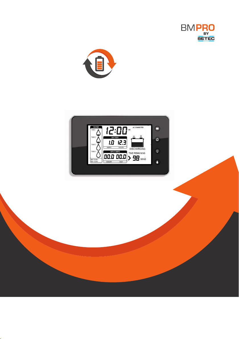
Trek
Manual
BATTERY MANAGEMENT TECHNOLOGY THAT
POWERS YOUR ADVENTURES
Doc 028515-C

2
CONTENTS
Introduction 3
Safety Precautions 3
Accessories 4
Other Required Items 4
About Trek 4
Glossary 5
Names and Functions of Parts 6
Operation 7
On Power Up 7
Description of Display Elements 8
Description of Buttons 9
Set-up Mode 11
Enabling Parameter Set-up Mode 11
Set-up Menu 11
Clock Menu 12
Water Tank Menu 13
New Battery Installation 16
Connectors 16
Installing Trek 16
Personnel 16
Installation Environment 16
Mounting 16
Trek to BatteryPlus35 Wiring 19
Water Tank Level Wiring 19
Servicing 20
Specications 20
After-sales Service 20
Repairs and After-sales Service 20
Warranty Terms and Conditions 21
Copyright © Setec 2015
Disclaimer
Setec accepts no liability for any loss or damage, which may occur as a result of improper or unsafe use of its products.
Warranty is only valid if the unit has not been modied by the customer and has not been misused.
Important Note: This product is only designed to work in conjunction with the BatteryPlus35 supply/charger. It will not interact with other products.

3
INTRODUCTION
SAFETY PRECAUTIONS
Please read the Safety Precautions carefully before installing the unit.
Failure to observe these instructions properly may
result in property damage or personal injury, which
may be serious depending on the circumstances.
Refer to the installation section before operating. Correct installation is the
most critical factor in ensuring the safe use of the power supply. If every
consideration of these instructions has been satised the power supply will be
safe to operate.
As this unit is powered by a communication cable it is critical that all
connections and cables are in a good and working order and properly
connected.
Do not allow water or other liquids to enter the installation area.
CAUTION

4
ACCESSORIES
The following accessories are provided with the retail pack for this product.
› A Trek Unit
› Front Fascia Plate
› Data Cable 10m
› Tank Loom
› Trek Manual
OTHER REQUIRED ITEMS
› 4 counter sunk screws for mounting, refer to Installing Trek for more details.
ABOUT TREK
The Trek is a display and control unit that connects to BatteryPlus35 and displays a range of
battery and water tank information. Its backlit LCD displays information including:
› Battery voltage
› Battery charging and discharging currents
› Auxiliary and solar charging currents
› Battery charge status
› Time remaining to discharge
› Level indication of up to 4 water tanks
› Time am/pm
› Water pump status
› Battery on/off status
Features also include:
› z which can be set as a night light
› Button to control 2 water pumps through BatteryPlus35
› Button to disconnect the battery from the loads
The above information is retrieved from BatteryPlus35 via the communication bus.

5
GLOSSARY
Loads
Consists of any appliance connected to the output terminal of the batteryPlus35 including
lights, TV, radio, etc.
Sources
Consists of any device that can supply power to BatteryPlus35 and its loads, such as solar
input, battery input, aux input and AC input.
Communication Bus
BatteryPlus35 and Trek are connected via a data cable and the communication between the
two devices is referred to as a communication bus.
BatteryPlus35
Integrated battery charger and power supply that converts 240VAC, Solar or Auxiliary DC
power to 12V DC which powers loads or charges a battery.

6
NAME AND FUNCTION OF PARTS
Tank 1 / Tank 2 / Tank 3 / Tank 4
Water tank level indicators. These can also
be turned into waste water tanks
Pump1 Status Indicator
Pump2 Status Indicator
Solar Current
Aux Current
Battery Charge State
This shows if the battery is charging or
discharging
Time Remaining
Time remaining for the battery to charge or
discharge
Water Pump Button
This button turns the pumps on and off
Back-light Button
Home Button
Home button is used for set-up functions
Battery Isolate Button
When paired with a BatteryPlus35, this
switch will isolate the battery from the loads
Set-up Mode Indicators
These indicators only appear when in setup
mode
Battery Off
Appears only when the Battery isolate
button is pushed
Battery Low
Appears only when Battery voltage is less
than 11V. This is set in the Battery alarm
menu
AC Connected
Charge Bar Graph
Battery Voltage
Clock
Battery Current
14
6
19
7
13
5
18
12
11
11
4
17
10
3
16
9
2
15
8
1
Names and Functions of Parts
Tank1, Tank2, Tank3 & Tank4
Water tank level indicators. These can also
be turned into waste water tanks.
Pump1 Status Indicator
Pump2 Status Indicator
Solar Current
Aux Current
Battery Charge State
This shows if the battery is charging or
discharging
Time Remaining
Time remaining for the battery to charge or
discharge
Water Pump Button
This button turns the pumps on and off
Back-light Button
Home Button
Home button is used for set-up functions
Battery Isolate Button
When paired with a BatteryPlus35, this
switch will isolate the battery from the loads
Set-up Mode Indicators
These indicators only appear when in set-
up mode
Battery Off
Appears only when the Battery isolate
button is pushed
Battery Low
Appears only when Battery voltage is less
than 11V. This is set in the Battery alarm
menu
7
10
11
12
13
9
8
7
6
5
4
3
2
1
Figure 1: Names and functions
14
11
10
9
8
5 7
6
4
15 13
14
1216
1
18
1719
2
3
11
Figure 1: Names and functions
7
OPERATION
In normal power-on mode the unit displays the Home screen.
Trek is designed to interface with BatteryPlus35. The functionality described below assumes
Trek has been correctly connected to BatteryPlus35.
The Trek will turn off if the battery voltage is less than 10.5V.
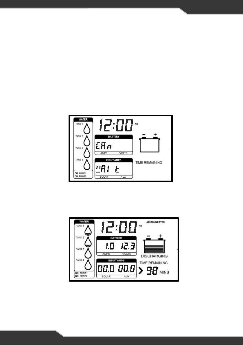
ON POWER UP
On Power up Trek will display “CAN WAIT” until communication between Trek and
BatteryPlus35 is established.
Figure 2: Trek display when rst powered up
AC Connected
Charge Bar Graph
Battery Voltage
Clock
Battery Current
Operation
In normal power-on mode the unit displays the Home screen.
Trek is designed to interface with BatteryPlus35. The functionality described
below assumes Trek has been correctly connected to BatteryPlus35.
The Trek will turn off if battery voltage is less than 10.5V.
On Power Up
On Power up Trek will display “CAN WAIT” until communication between Trek
and BatteryPlus35 is established.
When communication between Trek and BatteryPlus35 is established, Trek will
display information similar to the Figure 3.
8
16
17
18
19
15
Figure 2: Trek display when first
powered up
Figure 3: Trek displaying information after
initial power on, typical home screen.
When communication between Trek and BatteryPlus35 is established, Trek will display
information similar to the Figure 3.
Figure 3: Trek displaying information after initial power on,
typical home screen
AC Connected
Charge Bar Graph
Battery Voltage
Clock
Battery Current
Operation
In normal power-on mode the unit displays the Home screen.
Trek is designed to interface with BatteryPlus35. The functionality described
below assumes Trek has been correctly connected to BatteryPlus35.
The Trek will turn off if battery voltage is less than 10.5V.
On Power Up
On Power up Trek will display “CAN WAIT” until communication between Trek
and BatteryPlus35 is established.
When communication between Trek and BatteryPlus35 is established, Trek will
display information similar to the Figure 3.
8
16
17
18
19
15
Figure 2: Trek display when first
powered up
Figure 3: Trek displaying information after
initial power on, typical home screen.
If Trek cannot establish this communication within 30 seconds, then “CAN Err To” will be
displayed. If this occurs then, there is a fault in the system. Check all connections.

8
DESCRIPTION OF DISPLAY ELEMENTS
Tank1 / Tank2 / Tank3 / Tank4
Trek can support up-to 4 tank sensors and can be set-up as fresh water and/or waste water
tanks. By default, only Tank 1 and Tank 2 are set-up, as fresh water tanks. These indicate the
approximate water level in each of the tanks.
Fresh water tank
When the tank is installed and set-up as a fresh water tank, all 4 level segments are shown
when the tank is full.
Only the bottom level segment ashes and the other segments are not shown when the tank is
nearing empty or empty.
If a tank is not installed, that particular tank indicator will have no level segments shown.
Waste Water Tank
Water tanks can be set as waste water tanks, refer to the Water Tank Menu.
When a tank is set-up as waste water tank, all 4 level segments are shown and will be ashing
if the tank is full. When empty, only the bottom level segment is shown.
Pump Status Indicator
These indicators show if the pumps installed are on or off. This is controlled by the pump
button .
Solar Charge Current
This is the current that is drawn when the solar charger in BatteryPlus35 is active.
Aux Charge Current
Refers to the current that is drawn when the Aux in BatteryPlus35 is active.
Battery Charge State
A multi-segmented bar graph showing the state of charge of the battery. Below the bar graph
is displayed the word “CHARGING” or “DISCHARGING” according to the charging state of the
battery.
Time Remaining
Indicates the estimated time remaining for the battery to be charged to full or, discharged to
empty, assuming it continues to charge/discharge at the current rate. If the remaining time is
greater than 199 hours, the display shows “>199 HRS” and the battery is neither charging nor
discharging, the display is blank.
Set-up Mode Indicators
These indicators only appear when Trek is in set-up mode. The icons indicate the functions of
the buttons adjacent to it. The icons include edit, back, and symbol.
1
2
6
5
7
12
4
8
3
16

9
Battery Off
This indicator is only displayed when loads are disconnected from all sources including the
battery. This is controlled by the battery isolate button . All other segments will also be turned
off to reduce current draw from the battery.
Battery Low
This indicator shows when the battery voltage is at or below 11.0 Volts. It is recommended to
charge the battery at this point.
This is user congurable, refer to the Set-up Mode section.
AC connected
This indicator appears only when BatteryPlus35 is connected to AC mains.
Volts
Displays the battery voltage.
Amps
Shows the charging or discharging current of the battery.
Clock
Displays a 12 or 24 hour clock. This is user congurable. Refer to the Set-up Mode section.
DESCRIPTION OF BUTTONS
Water Pump Button
This button controls power to the water pump outputs on BatteryPlus35.
When BatteryPlus35 and Trek are rst powered, the outputs assigned for the pumps are ON
and Trek display “ON PUMP1” and “ON PUMP2” .
Pump1
To switch pump1 On/Off press the water pump button once.
Pump2
To switch pump2 On/Off press and hold pump button until the desired change is seen.
In set-up mode the water pump button turns into the “button”.
Back-light Button
Back-light button is primarily used to enable the back-light.
In set-up mode the back-light button is the “ button”.
Back-light Functionality
Turn on back-light temporarily: Press any button to turn ON the back-light temporarily and
will automatically turn off after 30 seconds.
Turn on night-light: Press and hold the back-light button until the back-light blinks
(approximately three seconds). The back-light will turn ON for 10 hours.
Turn off night-light: Press and hold the back-light button until the back-light is OFF.
13
14
15
17
19
18
8
32
8
8
9

10
Home Button
Pressing and holding the Home button for approximately 5 second puts Trek into the set-up
mode.
In set-up mode the home button is the “back button”.
Battery Button
The battery button is used to disconnect the battery, AC mains, auxiliary and solar sources
from the loads.
When Trek is rst turned on the battery will power the loads and “BATTERY OFF” is NOT
displayed. When the battery button is pressed, the loads are disconnected from the battery
and “BATTERY OFF” will appear and all other segments will also be turned off to reduce
current draw from the battery.
Pushing the battery button will toggle the loads ON and OFF.
In set-up mode the battery button is the “EDIT button”.
10
11
13
11
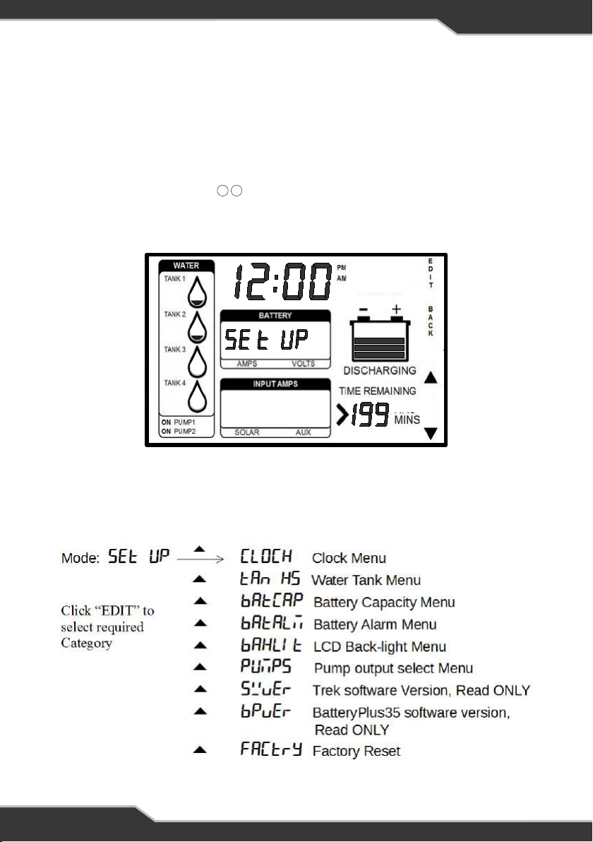
SET-UP MODE
ENABLING PARAMETER SET-UP MODE
1. Ensure the display is in normal mode (not in any setting mode).
2. Press and hold the Home button for at least 5 seconds.
3. “SETUP” will be displayed in location.
4. Now you are in set-up mode.
17 19
Figure 4: Set-up Mode
Set-up Mode
Enabling Parameter Set-up Mode
1. Ensure the display is in normal mode (not in any setting mode).
2. Press and hold the Home button for at least 5 seconds.
3. “SETUP” will be displayed in location
4. Now you are in set-up mode
Set-up Menu
When in set-up mode, the “” or “” button can be used to scroll through the set-
up menu. The list of options in the set-up menu is as follows:
12
17 19
Figure 4: Set-up Mode
When in set-up mode, the “or” button can be used to scroll through the setup menu. The list of
options in the set-up menu is as follows:

12
CLOCK MENU
When in set-up mode use the following.
Set-up 12hr Clock
Clock Menu
When in set-up mode the following needs to be followed.
Set-up 12hr Clock
AM and PM annunciators will automatically change as the time changed from 11
to 12.
To exit, keep pressing the “Back” button until the home screen is seen.
Set-up 24hr Clock
To exit, keep pressing the “Back” button until the home screen is seen.
Water Tank Menu
To exit menu, keep pressing the “Back” button until the home screen is seen.
Water Tank Enable
This shows how to enable or disable the water tanks.
After enabling the required tank, allow for 15 seconds for the tank levels to
update.
13
AM and PM annunciators will automatically change as the time changed from 11 to 12.
To exit, keep pressing the “Back” button until the home screen is seen.
Set-up 24hr Clock
To exit, keep pressing the “Back” button until the home screen is seen.

13
Water Tank Method
This shows how to choose the water tank method. It allows the installer to
choose the type of sensing depending on the sensor used, analog or digital.
Water Tank Type
This shows how to change the water tank from a fresh water to waste water
tank.
14
Water Tank Method
This shows how to choose the water tank method. It allows the installer to
choose the type of sensing depending on the sensor used, analog or digital.
Water Tank Type
This shows how to change the water tank from a fresh water to waste water
tank.
14
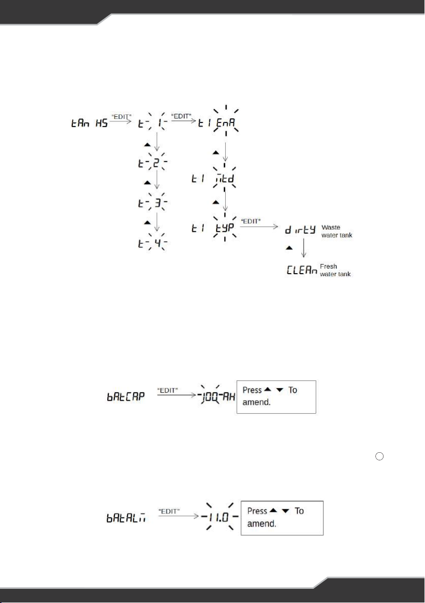
WATER TANK MENU
To exit the menu, keep pressing the “Back” button until the home screen is seen.
Water Tank Enable
This shows how to enable or disable the water tanks.
After enabling the required tank, allow for 15 seconds for the tank levels to update.
Water Tank Method
This shows how to choose the water tank method. It allows the installer to choose the type of
sensing depending on the sensor used, analog or digital.
14
Water Tank Type
This shows how to change the water tank from a fresh water to waste water tank.
Battery Capacity Menu
This shows how to change the battery capacity in AH. The battery capacity can be
incremented or decremented.
When a new battery is fitted, set this to the nominal battery capacity (as marked
on the battery); doing this will assist the software in determining the actual
capacity.
Battery Alarm Menu
This shows how to change the battery alarm. This parameter indicates when the
Battery Low annunciator starts to blink. The alarm threshold can be
incremented or decremented in steps of 0.5V. The alarm threshold can be
adjusted from 10.5V to 12.5V.
15
14
LCD Back-light Menu
This shows how to change the LCD back-light brightness. The back-light
brightness can be incremented or decremented in steps of 10%. The
brightness can be adjusted from 10% to 100%.
Factory Reset Menu
This shows to to restore Trek back to factory settings.
WARNING: All saved
settings will be erased.
16
Battery Capacity Menu
This shows how to change the battery capacity in AH. The battery capacity can be
incremented or decremented.
When a new battery is tted, set this to the nominal battery capacity (as marked on the
battery); doing this will assist the software in determining the actual capacity.
Battery Alarm Menu
This shows how to change the battery alarm. This parameter indicates when the Battery Low
annunciator starts to blink. The alarm threshold can be incremented or decremented in steps of
0.5V. The alarm threshold can be adjusted from 10.5V to 12.5V.
14

15
LCD Back-light Menu
This shows how to change the LCD back-light brightness. The back-light brightness can be
incremented or decremented in steps of 10%. The brightness can be adjusted from 10% to
100%.
LCD Back-light Menu
This shows how to change the LCD back-light brightness. The back-light
brightness can be incremented or decremented in steps of 10%. The
brightness can be adjusted from 10% to 100%.
Factory Reset Menu
This shows to to restore Trek back to factory settings.
WARNING: All saved
settings will be erased.
16
LCD Back-light Menu
This shows how to change the LCD back-light brightness. The back-light
brightness can be incremented or decremented in steps of 10%. The
brightness can be adjusted from 10% to 100%.
Factory Reset Menu
This shows to to restore Trek back to factory settings.
WARNING
: All saved
settings will be erased.
16
Factory Reset Menu
This shows how to restore Trek back to factory settings.

16
NEW BATTERY INSTALLATION
Trek is a smart battery monitor that is able to learn the actual battery capacity and thus provide
more accurate “Time Remaining” feedback to the user. When an existing battery is replaced by
a new one, check the capacity of the new battery verify this in Battery Capacity Menu on page
4. Change this as required.
Fitting a new battery and doing nothing else will result in the “Time Remaining” display initially
being inaccurate. It is recommended to charge the battery until Trek shows its full for a better
accuracy reading.
See BatteryPlus35 installation instructions for more information on the installation of new
battery.
CONNECTORS
At the rear of Trek are two connectors.
1. The communication bus connector which is a data cable that connects BatteryPlus35
to Trek.
2. The Tanks Sensor connector with a detachable loom. This loom can be connected to 4
digital tank sensors.
Note: The digit '1' is moulded into the rear of Trek case beside each connector, indicating the
location of pin 1.
INSTALLING TREK
PERSONNEL
Installation is to be carried out only by suitably qualied personnel.
INSTALLATION ENVIRONMENT
Trek should be installed indoors where it will not be subject to water or other liquid spills or
splashes.
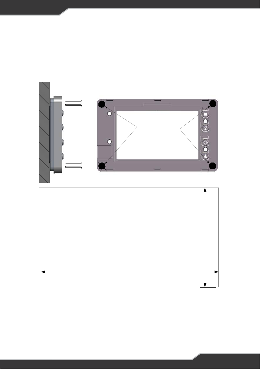
MOUNTING
Trek is designed to be mounted to the wall directly with counter sunk screws. It can be
mounted in two methods depending on the look and application required. The mounting
methods and required mounting holes are specied below. The cut-outs below each method
are also to allow space for connectors at the back of Trek. These cut-outs are to scale and can
be used to cut the hole in the wall before xing the unit.
After xing Trek to the wall attach the provided front fascia plate to Trek. This fascia clips on to
the front of Trek.

17
Figure 5: Mounting Method 1 Details
Screw requirement for mounting method 1:
Screw type: Counter sunk
Diameter: 4.0mm Max
Length: 25mm Min
After fixing Trek to the wall attach the provided front fascia plate to Trek. This
fascia clips on to the front of Trek.
Screw requirement for mounting method 1:
Screw type: Counter sunk
Diameter: 4.0mm Max
Length: 25mm Min
18
Figure 5: Mounting Method 1 Details
Mounting Holes
Countersunk screws
Recommended
33mm
105mm
Suggested cut out
size for Flush mount
18
Figure 6: Mounting Method 2 (RECESS) Details
Screw requirement for mounting method 2:
Screw type: Counter sunk
Diameter: 3.5mm Max
Length: 20mm Min
Screw requirement for mounting method 2:
Screw type: Counter sunk
Diameter: 3.5mm max
Length: 20mm min
19
Figure 6: Mounting Method 2 (RECESS) Details
Mounting Holes
Countersunk screws
Recommended
74mm
134mm
Suggested cut out
size for Recessed mount
Screw requirement for mounting method 2:
Screw type: Counter sunk
Diameter: 3.5mm max
Length: 20mm min
19
Figure 6: Mounting Method 2 (RECESS) Details
Mounting Holes
Countersunk screws
Recommended
74mm
134mm
Suggested cut out
size for Recessed mount

19
Trek to BatteryPlus35 Wiring
20
Figure 7: Trek to BatteryPlus35 Wiring
DATA Cable
Water Tank Loom
Trek
BP35
Water Tank
Sensor
Tank4 Tank1
Tank2
Tank3
TREK TO BATTERYPLUS35 WIRING
Figure 7: Trek to BatteryPlus35 Wiring
WATER TANK LEVEL WIRING
Digital Sensor
1. Empty the water from the tank(s)
2. Choose a suitable side of the tank where the level-sensing bungs can be located.
3. Drill the required holes in the tank
4. Install the tank sensor to the tank
5. Connect sensor connector to the water tank loom
6. Fill the tank(s) and check for water leaks around the bungs. Reseal as necessary.
7. Test operation of water level sensors, water pump switch, and Battery on/off switch.

20
Specication
Input Voltage 8 – 15 Vdc
Battery Drain < 21 mA (backlight off)
Ambient Temperature 0 ºC – 50 ºC
Size 149 Wide x 85 High x 22 Deep
SPECIFICATIONS
SERVICING
AFTER-SALES SERVICE
Do not disassemble, modify, or repair the unit.
Doing so may result in electric shocks or re.
REPAIRS AND AFTER-SALES SERVICE
Consult your BM PRO by Setec dealer.
TROUBLE-SHOOTING
Trek not responding; If the Trek seems to have stopped responding while pressing buttons,
wait for 30 seconds and the Trek will reset and resume operation.
WARNING
There are no internal user serviceable parts
Table of contents
Popular Control Unit manuals by other brands


Blackbe;rry
Blackbe;rry ITB100-1 installation guide

red lion
red lion CSTC manual

Power Fist
Power Fist 8003441 user manual

Contec
Contec F&eIT Series quick start guide

Keyautomation
Keyautomation CT-724 Series Instructions and warnings for installation and use

Blu Stream
Blu Stream Multicast ACM200 API Documentation


