Ver.1.01
CNT24-2(FIT)GY 3
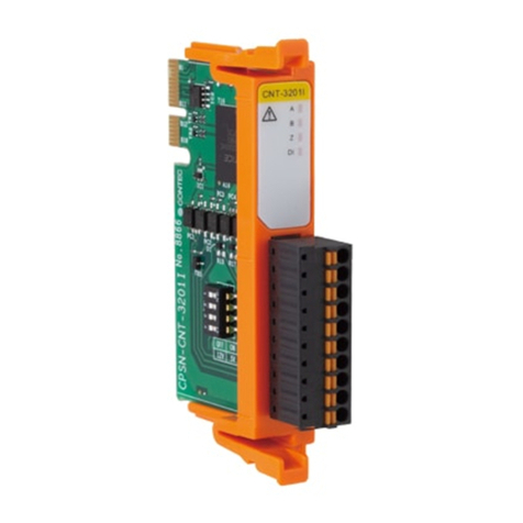
When connecting the Module to an external device, you can
use the supplied connector plug. When wiring the Module, strip
off approximately 7 - 8 mm of the covering for the cable, and
insert the bare wire by pressing the orange button on the
connector plug. Releasing the orange button after the wire is
inserted to fix the cable. Compatible wires are AWG 28 - 20.
Press this section to insert
the wire material.
7 - 8mm
CNT24-2
Device
ID
ABZD1
CH
PCOM
PA
PB
PZ
PD1
EQ.P
EQ
EQ.N
0
4
0
4
6
2
5
1
3
7
PCOM
PA
PB
PZ
PD1
EQ.P
EQ
EQ.N
CH
CH
CH
- Connector used:
2.5mm pitch, 9-pin type, 4.0A nominal current
MC0,5/9-G-2,5 connector (made by Phoenix Contact Corp.)
- Applicable plug:
Front-operable spring gauge type
FK-MC0,5/9-ST-2,5 plug (made by Phoenix Contact Crop.)
Applicable wire: AWG 28 - 20
CAUTION
Removing the connector plug by grasping the cable can
break the wire.
The Module can be connected to an external device using a
9-pin (1 group) connector that is provided on the Module face.
9
8
7
6
5
4
3
2
1
CH0
PCOM(0)
PA(0)
PB(0)
PZ(0)
PDI(0)
EQ.P(0)
EQ(0)
EQ.N(0)
N.C.
Plus common for channel 0 input signals
Channel 0 phase A input
Channel 0 phase B input
Channel 0 phase Z input
Channel 0 general-purpose digital input
Plus common for channel 0 output signals
Channel 0 count-match output
Minus common for channel 0 output signals
Not connected
9
8
7
6
5
4
3
2
1
CH1
PCOM(1)
PA(1)
PB(1)
PZ(1)
PDI(1)
EQ.P(1)
EQ(1)
EQ.N(1)
N.C.
Plus common for channel 1 input signals
Channel 1 phase A input
Channel 1 phase B input
Channel 1 phase Z input
Channel 1 general-purpose digital input
Plus common for channel 1 output signals
Channel 1 count-match output
Minus common for channel 1 output signals
Not connected
220
Opto-coupler
2.2k
Module External circuit
Input
pin
+5V
Plus common
External device
signal output
220
Opto-coupler
2.2k
Input
pin
+12V
External device
signal output
400
R
Plus common
CAUTION
The general-purpose input signal also has a similar circuit
configuration.
When an external power supply other than 5V is used,
insert a current-limiting resistor at position R. If PV
denotes an external power supply, the current-limiting
resistor R can be calculated as follows:
P - 5
20 < Rk<P - 5
15
For example, P = 12V will require the following resistance:
350< R < 470
When there is a match between a channel count and a
specified value, a one-shot (one pulse) match signal is output
to the outside. The signal output section has an open
collector configuration based on opto-isolation. Driving the
output of this module requires an external power supply.
Output
pin
Opto-coupler
Plus
common
Minus
common
Load External
power
supply
5V - 12VDC
Vcc Module External circuit
CAUTION
A surge voltage protection circuit is not provided on the
output transistors for this Module. Therefore, when
driving relays, lamps, and other induction loads using this
Module, a surge voltage countermeasure should be
provided on the load side.
For details, see the manual, chapter 3 “Surge Voltage
Countermeasures".
How to Connect an Interface Connector
Signal Layout on the Interface Connector
Connecting to a Opto-Isolated Input Circuit
Output Circuit and an Example Connection


