Seura Hydra S-1913-19.1-HY.1 User manual

IMPORTANT: Please read this operation manual before operating the equipment.
Waterproof 19" High-Definition
Liquid Crystal Television
User
Manual
19”TFT-LCD Television
Model: S-1913-19.1-HY.1
2
Thank you for purchasing Hydra™ waterproof 19"TFT-LCD television.
Please take the time to read this manual for the best performance of your new
television.To enjoy the features of this unit and ensure years of trouble-free
operation, please make sure to carefully follow instructions.
Please keep this manual for future reference.
Information in this manual is subject to change without prior notice.
CAUTION
A. Any changes or modifications in construction of this device which are not
expressly approved void the manufacturers warranty.
B. Do not attempt your own maintenance. If a problem occurs, please turn
theTV off and consult yourTV Dealer or Supplier. Opening or altering the
appliance by unauthorized persons results in void of warranty.
C. Do not expose theTV to extreme environmental conditions such as high
humidity, direct sunlight, dust, steam, smoke or excessive hot or cold
temperatures.
BY SÉU R A ®
™

3
SAFETY INSTRUCTIONS
To reduce the risk of fire, electrical shock and other
injuries, keep these safety precautions in mind when
installing, using, and maintaining yourTV.The socket-
outlet should be installed near the equipment and
be easily accessible.TheTV should be connected to a
grounded main socket outlet.
WARNING: If you manipulate against the
recommended usage, serious injury or death to user
may result.
For added safety during a lighting storm, or when this product is left unattended and
unused for long periods of time, unplug it from the wall outlet and disconnect the
antenna.
Do not touch the power cord with wet hands.
If any electric pin is wet or dusty, remove the moisture or dust before use.
Do not use a damaged power cord or plug.
Do not use the product close to any heat sources such as radiators, heat registers,
stoves, or other products that produce heat.
Do not place heavy articles or step on the product.
Placing the product on an unstable base can cause the product to fall, resulting in
serious personal injuries as well as damage to the product.
If you notice any smoke or scorched smell near the product, unplug power cord and
refer to qualified personnel for service and/or repair.
Do not use or place any combustible or flammable substances near
the product.
An outside antenna system should not be located in the vicinity of overhead power
lines or other electric light or power circuits, or where it can fall into such power lines
or circuits.
Turn off the main power and unplug the AC cord from the wall outlet before handling.
Do not operate in direct sunlight.
Safety Tips

4
CHAPTER 1
Set Up
1-1 InThe Box.................................................. 7
1-2 Parts........................................................... 8
1-3Terminals ................................................... 9
1-4 Installation............................................... 10
1-5 Remote Control....................................... 15
1-6 Insert Remote Control Batteries ............ 17
1-7 Menu Controls on Remote..................... 18
1-8 Menu Configuration ............................... 19
1-9 Basic Operation ..................................... 20
CHAPTER 2
Connection
2-1 Preparation ............................................. 22
2-2 Connecting Power .................................. 22
2-3 ConnectingTV Antenna.......................... 23
2-4 Connecting VIDEO / S-VIDEO ................24
2-5 Connecting HDMI ................................... 25
2-6 Connecting PC ........................................ 26
2-7 Connecting RS-232C PC Control ...........28
2-8 Connecting Audio Lineout..................... 28
Contents

5
CHAPTER 3
Menu
3-1The Menu System.................................... 30
3-2 Video Menu.............................................. 31
3-3 Audio Menu ............................................. 39
3-4 TV Menu................................................... 41
3-5 Setup Menu ............................................. 46
3-6 Parental Menu ......................................... 55
CHAPTER 4
Specifications
4-1 Specifications .......................................... 63
CHAPTER 5
Troubleshooting
5-1Troubleshooting....................................... 66

6
1-1 InThe Box
1-2 Parts
1-3Terminals
1-4 Installation
1-5 Remote Control
1-6 Insert Remote Control Batteries
1-7 Menu Controls on Remote
1-8 Menu Configuration
1-9 Basic Operation
1
Set Up

7
Please make sure the following items are included:
Hydra™ waterproof LCD product:
1) Back Box
2)TV Assembly
Waterproof Sealant
20 ft Low-Voltage Power Cord, CL2R
Power Supply Brick: 110-240V
Standard USA-A type plug
Waterproof Remote Control with battery
Mounting Hardware
User Manual
1-1 In The Box

8
1-2 Parts
2) TV ASSEMBLY
1) BACK BOX
INPUT/OUTPUT/LOW VOLTAGE
PASS-THROUGH PORT
TOP
TOP
BOTTOM
BOTTOM
FRAMING
MEMBER
SCREW-
MOUNTING
SLOTS (4,
2 PER SIDE)
FRAMING MEMBER
SCREW-MOUNTING
SLOTS (4)
LOW VOLTAGE
POWER LOCATION
ON-UNIT
CONTROL
BUTTONS
GLASS FACE
GRAVITY
LOCK
GUIDE
SLOTS (4)
GRAVITY LOCK MOUNTS
INPUTS/OUTPUTS

9
ON-UNIT CONTROL BUTTONS
1.3 Terminals
15 Pin VGA Input
DTV/Antenna
PC Audio In (blue)
PC Audio Out (green)
Composite
S-Video
Component Input RGB
RS 232 Input
HDMI Input
DC Power Input
2 Channel Amplified
Speaker Out
5’ IR Lead with 3.5 mm
Male Connector
BOTTOM
GLASS
FACE
1) BACK BOX
NOTE:THIS VIEW SHOWS
BACK BOX ANDTV ASSEMBLY
INSTALLEDTOGETHER
2)TV ASSEMBLY
Source
Menu
Power
Volume
Channel
10
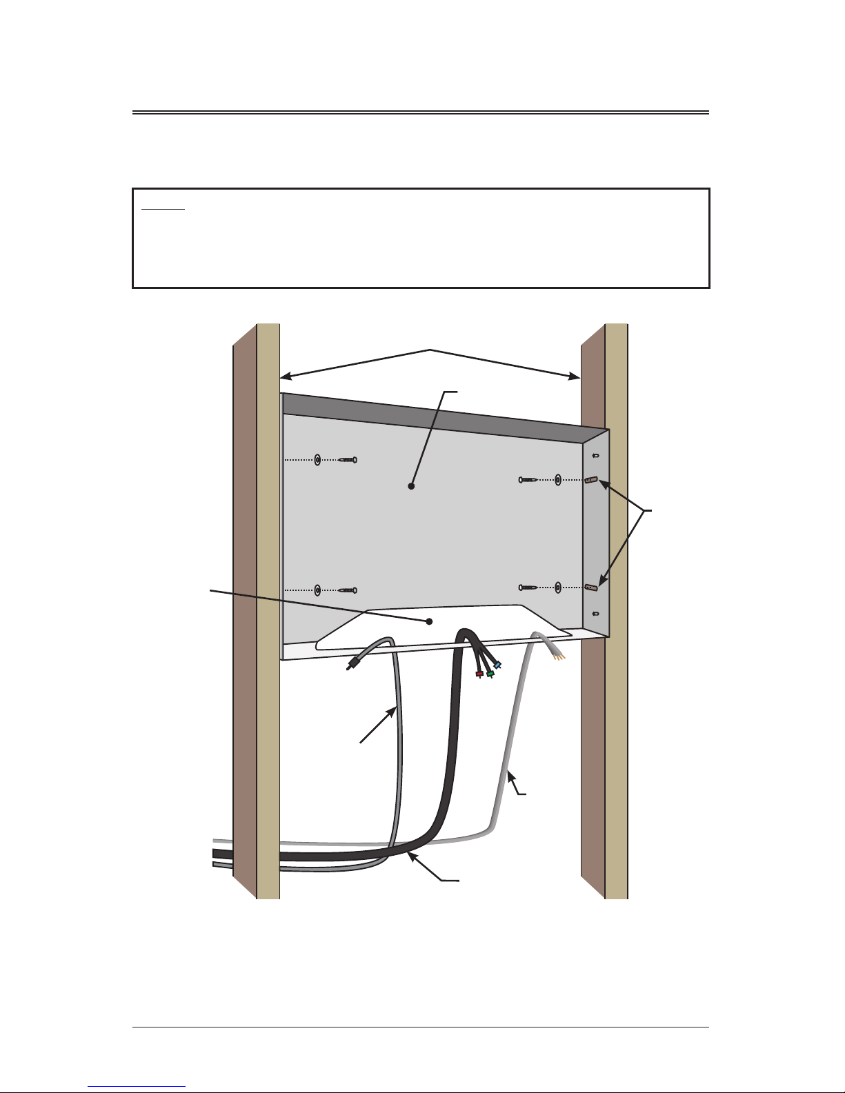
1-4 Installation
Step 1
Install back box in unfinished wall to framing members using the provided four
screws and washers through screw-mounting slots in back box. Ensure that the
front of the box will be flush with finished wall when installed. Feed power and
other desired cords through pass-through port.
NOTE: Read all installation instructions before beginning installation.
1) BACK BOX
VERTICAL FRAMING MEMBERS
SCREW
INTO
FRAMING
MEMBERS
USING
SCREW-
MOUNTING
SLOTS (4)
PASS-
THROUGH
PORT
LOW-
VOLTAGE
POWER
AUDIO
VIDEO
Note: Do not overtighten mounting hardware. Back box should fit snuggly between
framing members. If the fit is poor, and overtightening occurs, the back box may
deform, resulting in a poorly sealed installation. If the back box doesn’t fit well
between framing members, shim the framing members for a square and stable fit.

11
Step 2
While keeping
cord ends outside
the back box
pass-through
port, finish the
wall tight to the
edges of back
box, removing
any gap. Once
complete, the
final wall surface
should be flush
with the front
edge of the back
box as shown.
1) BACK BOX
MAINTAIN
CORDS
IN PASS-
THROUGH
PORT
DURING
WALL
FINISHING
FINISHED
WALL
FINISHED WALL
WALL BOARD
FRAMING
MEMBER
SCREW
MOUNTING
SLOTS
NOTE:
SURFACE OF
FINISHED
WALL AND
FRONT EDGE
OF BACK
BOX ARE
FLUSH
1) BACK BOX

12
RECESSED INPUT/OUTPUT/
LOW VOLTAGE LOCATION
BACK BOX IS SCREW
MOUNTED INTO
FRAMING MEMBERS
GLASS FACE
1/8” BEAD
(EXCESS
SEALANT
SHOULD SEEP
OUT ON ALL
EDGES WHEN
FULLY ENGAGED)
1)TV ASSEMBLY
Step 3
InstallTV Assembly:
A) PlaceTV assembly face down on a clean, dry surface near the installed
back box. Make all necessary connections and ensure LCD operation is
successful.Tip: Use a small table or stool as near to the installed back
box as possible to reduce wire slack.
B) Before applying adhesive, “dry fit” theTV assembly in back box. Notice
that the gravity lock mounts engage and ensure remote and LCD
functionality in installed position.
C) RemoveTV assembly from back box and place face down near back box.
Do not disconnect any wires. Clean any residue from glass and remove
debris.
D) Apply supplied waterproof sealant liberally to glass face edge as shown.
Affix to wall surface, ensuring gravity lock mounts are fully engaged.
Sealant should seep out the front on all edges to provide the best seal.

13
PASS-
THROUGH
PORT
LOW VOLTAGE
POWER CABLE
2) BACK BOX
Note: Immediately afterTV assembly is installed
and sealed, verify functionality of LCD and
remote. If operation has been compromised by
the installation, corrections can easily be made
until the sealant has cured.
14
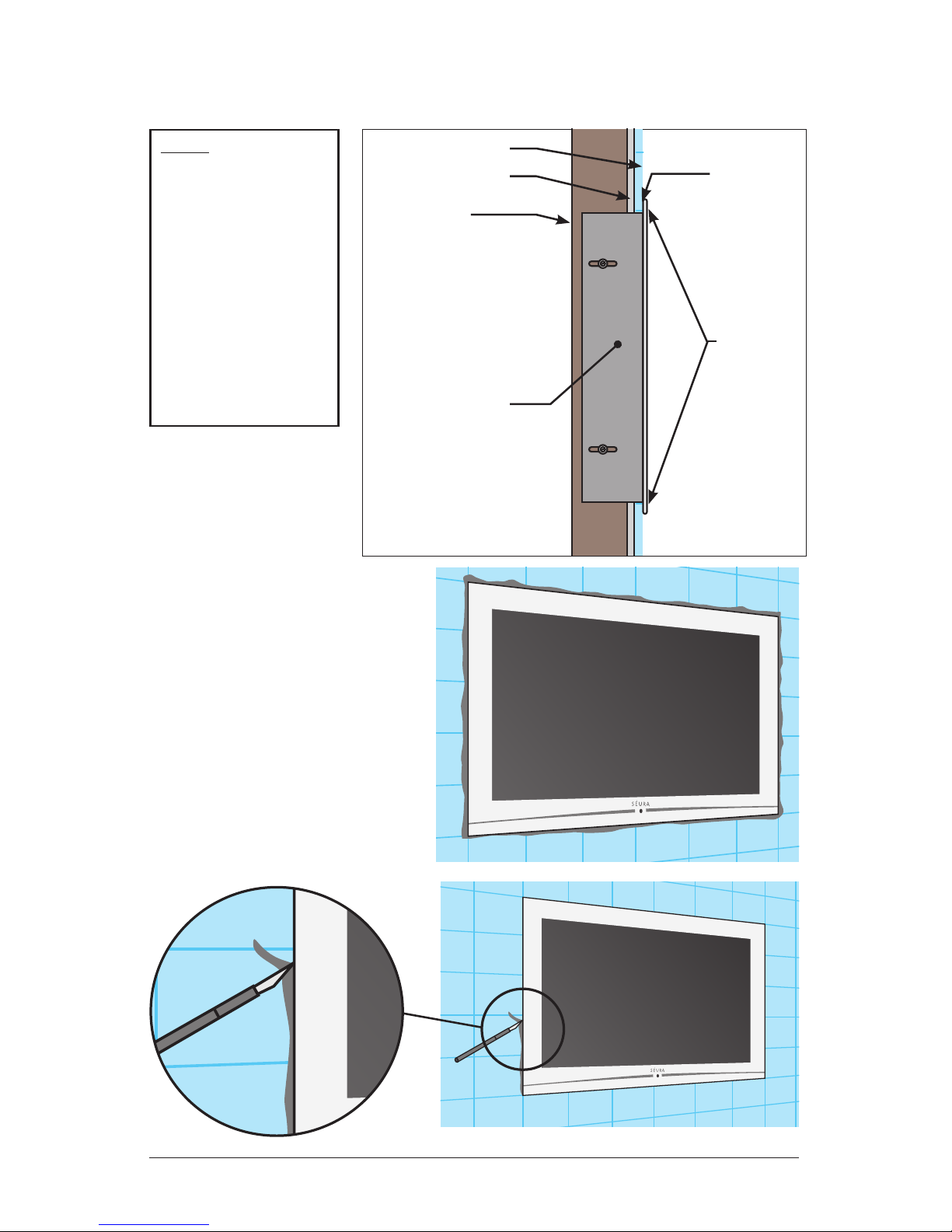
Step 4
Allow waterproof
sealant 24 hours to
cure at 72 degrees
Fahrenheit before
exposing to moisture.
(or recommended
time designated by
sealant instructions)
Once fully cured,
use a razor blade or
utility knife to remove
excess sealant.
FINISHED WALL
WALL BOARD
FRAMING
MEMBER
NOTE:
GLASS
FACE-
PLATE
SEALS
DIRECTLY
TO
FINISHED
WALL
SURFACE
SEALANT
CREATES
WATER-
TIGHT
SEAL
COMPLETELY
INSTALLED
BACK BOX AND
TV ASSEMBLY

15
Power On/Off, Standby
TV & Input Source
Selection Button
Display Button
Menu Control Center
SleepTimer Button
Zoom Button
Electronic Program
Guide Button
Mute Button
Number Selection
Buttons
Channel Control
Buttons
Volume Control
Buttons
Enter Button
1
2
3
4
5
6
7
8
9
10
11
12
9
5
6
8
7
12
10
11
1
4
2 3
Remote performs best within
20 ft (6 m) of the LCD and
within 30º to the left or right
of the display.
1-5 Remote Control
16
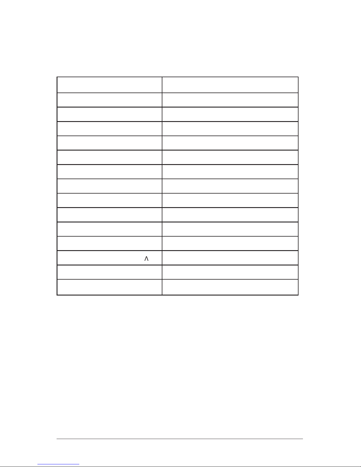
POWER Power On/Off, Standby
SOURCE Select Input Source
DISPLAY Display current program details
MENU Display and edit menu screen
EXIT Exit current screen
Arrows (3456) Control menu options
OK Confirm selection
SLEEP Set sleep timer
ZOOM Zoom current picture
EPG View available electronic program guide
MUTE Temporarily turn off audio
0 - 9, . Numeric selection
Channel Control Buttons (V ) Select control
Volume Control Buttons (+ -) Volume control
ENTER Confirm selection
Functions by remote control buttons
Button Function
17
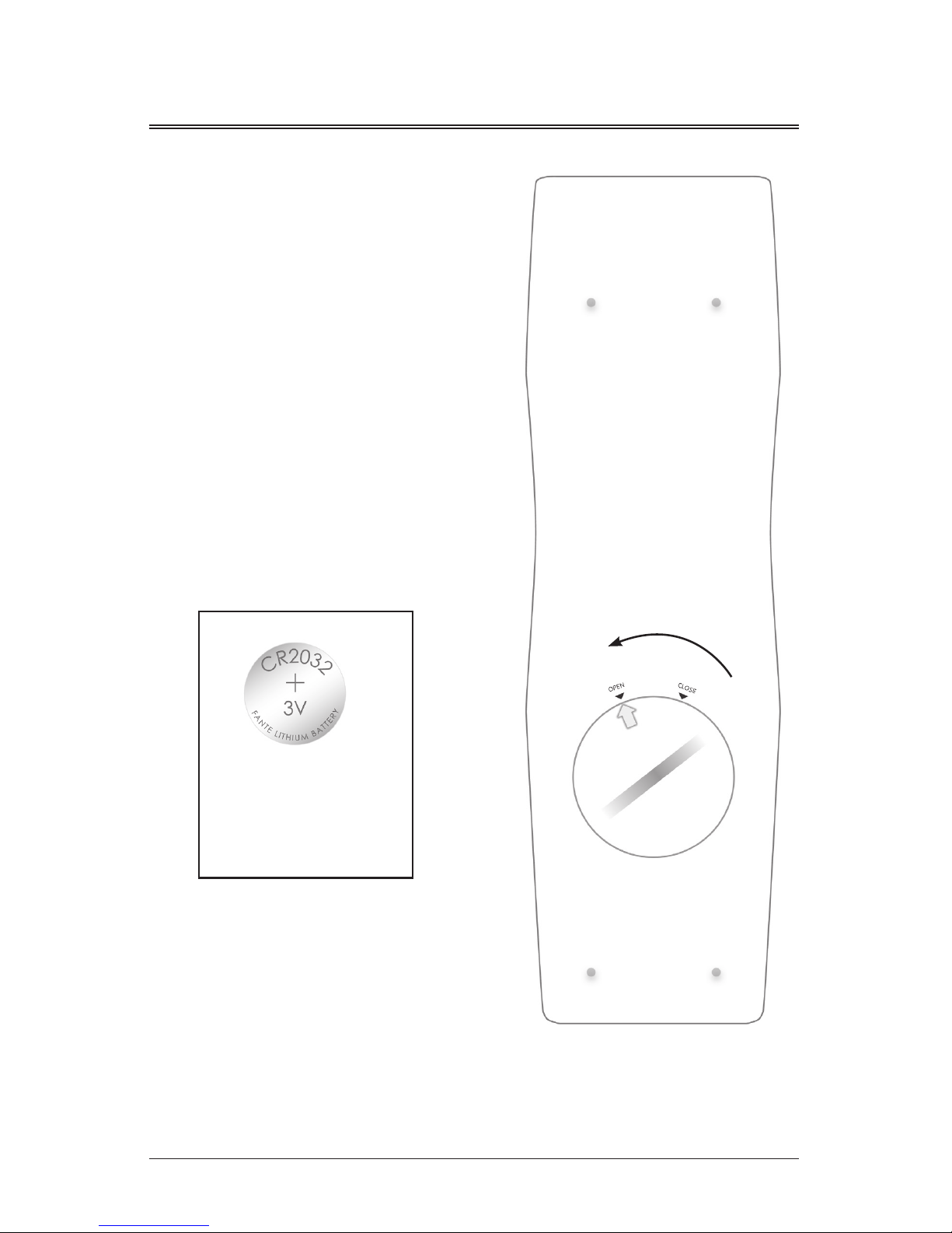
Remove the battery cover on the back of
the remote using the tool included or a
coin.
Open compartment and remove battery
and safety tab.
Discard plastic safety tab.
Reinsert the battery, positive side out
(the side with writing facing out).
Ensure waterproof ring is securely in
place before returning cover.
Return cover and turn to “CLOSE”
position.
Battery:
CR2032 + 3V
Lithium Battery
1-6 Insert Remote Control Batteries

18
Press MENU button on the remote
control to display main menu.
1-7 Menu Controls on Remote
Press menu control arrow buttons
to navigate through menus. Use
the right arrow (4) to move to sub
menu of a selected main menu.
Press EXIT button to return from
sub menu to main menu or from
main menu to menu removal.
To change a selected menu setting,
use Menu control buttons (34).
Functions of theTV set can be controlled by the Menu Control Center on the remote
control. Familiarity with these functions will provide ease of operation.
19
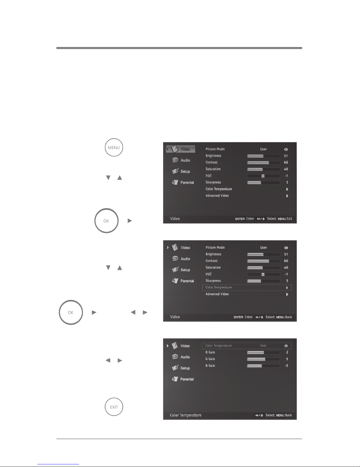
Press MENU to open the menu window. Navigate using 5 or 6 to select the desired
menu. Press 4 or OK to enter the menu. Use 5 or 6 within the selected menu to
navigate to a submenu or setting to adjust. Press 4 or OK to enter the submenu or
use 3or 4 to adjust selected setting. Press EXIT at any time, or wait 10 seconds to
exit the menu.
1-8 Menu Configuration
OR

20
Power On / Off
Press the Power / Standby button on the remote control or on the side panel to
turn on the unit.
Press Power / Standby button on the remote control or on the side panel again to
return the display to standby (off) mode.
Selection
of Input Mode
Press the Source
button to display the
signal source menu.
Press 5 or 6to
select the signal
source you desire,
then press OK to
confirm.
1-9 Basic Operation
Table of contents
Other Seura LCD TV manuals


