Seventh Circle Audio B16 User manual

B16 Compressor Rev 2.1
Designed around the THAT 4305 dynamics processor IC, the B16 is a fairly easy to build and
use compressor that is useful in a wide variety of applications. The low distortion VCA, Burr-
Brown op-amps, and state of the art line driver and receiver ICs combine to form a transparent
circuit that keeps levels under control while adding a minimal sonic imprint. An optional
transformer allows for a true floating output and some transformer color, if desired. Attack and
release timing is generated by a program dependent non-linear capacitor circuit that eliminates
the need for separate attack and release controls.
Who Should Build This Kit?
The B16 is not difficult to build, well, other than the 4305 IC…but it also is not intended for
absolute beginners. The soldering on the 4305 IC can be done by SCA for an additional
charge! You should have built at least one project on a printed circuit board (PCB) before trying
the B16. Sorry, but soldering cables doesn’t count. If you’ve never built an electronic project
of any kind, this is probably not the one to start with. To guarantee success make sure you
have:
•The ability to make basic voltage and resistance measurements using a digital multi-
meter (DMM).
•At least a rudimentary understanding of Ohm’s Law and the relationship between
voltage, current, and resistance.
•Some experience soldering on printed circuit boards.
•The patience to follow instructions precisely and work carefully.
Essential Tools
Fine tipped 20-30 Watt soldering iron w/ cleaning sponge (Hakko 936 or similar)
Eutectic (63/37) rosin core or “no clean” solder (.025” diameter is usually best)
Good-quality DMM
Small needle nose pliers
Small diagonal cutters
Phillips screwdriver (#1)
Flat jeweler’s screwdriver
Highly Recommended Tools
Lead bender (Mouser 5166-801)
Magnifying glass
To adjust makeup gain, you’ll need the ability to generate and measure audio test signals
between –20dBu and +20dBu. Most DAWs can accomplish this task.

Optional Tools
Panavise with circuit board head (PV-312, PV-300, and PV-315 or PV-366) Oscilloscope
Signal generator
Work Area
Find a clean, flat, stable, well-lit surface on which to work. An anti-static mat is recommended
for this project. If you’re in a dry, static-prone environment, it’s highly recommended. The
importance of good lighting can’t be overstated. Component markings are tiny, and you’ll be
deciphering a lot of them.
Soldering Technique
Make sure your iron's tip is tinned properly and keep it clean! The trick to making perfect
solder joints is to heat the joint quickly and thoroughly before applying the solder, and a
properly tinned and clean tip is essential for this. Apply enough solder to form a "fillet"
between the lead and the pad, a little mound of solder that smoothly transitions from the plane
of the board up to the lead, but don’t use too much. The finished joint should be smooth and
shiny, not rough or gritty looking.
If you've never soldered a board with plated-through holes, you might be surprised to discover
how difficult it can be to remove a component once you've soldered it in place. If you're using
solder wick to correct a mistake, be very careful not to overheat the pads, since they will
eventually delaminate and "lift". It's often better to sacrifice the component and remove its
leads individually, then start over with a new part. If for some reason you need to unsolder a
multipin component (like a rotary switch or integrated circuit), remove as much solder as you
can with solder wick or a solder sucker, and then use a small heat gun to heat all the leads
simultaneously. With care, you can remove the component without damaging the board.
Instruction Conventions
Text in orange indicates a step where extra care needs to be taken. Doing it wrong isn’t a
disaster, but it’ll need to be corrected.
Text in red indicates a step that must be done correctly. Doing it wrong will guarantee
improper operation, and probably damage components and/or the circuit board.
Assembly
1. Before you begin, carefully unpack the kit and examine the parts. Check the contents of
each small bag against the BOM to make sure all the parts have been included. If you
think something’s missing, please e-mail the details to sa[email protected]
and we’ll ship replacement parts ASAP.
2. Generally, the idea when "stuffing" or “populating” a circuit board by hand is to start with
the lowest profile parts, such as the resistors, and work your way up to the taller
components. In each step below, insert the components, flip the board onto your work
surface component-side down, and carefully solder and trim the leads.

Use a piece of stiff cardboard to hold the parts in place while you flip the board. First,
orient the board as shown.
3. Before installing the resistors, prepare
the leads using small needle nose
pliers or a lead-forming tool as shown
here. Whatever you do, don’t bend
the leads at the resistor body and
force them into the board.This not
only results in an ugly job, but it can
also damage the parts.

4.
Solder U1 taking EXTRA care to not use too much solder and create shorts! Use a
microscope, magnifying glass, or cell phone camera, zoomed in, to check your
work! IF YOU ARE UNCOMFORTABLE SOLDERING THIS PART, SCA CAN SOLDER
IT FOR YOU FOR A SMALL CHARGE!
5. Insert the 1/4-watt resistors. Check the Bill of Materials (BOM) for help in reading the
resistor color bands. It's also a good idea to actually measure each resistor with your
DMM as you place it on the board, just in case you've read it incorrectly. Don't rely on the
photos for component placement. If the resistor value silk-screened on the board doesn't
agree with the value on the schematic or parts list, follow the schematic. You can leave
out the two ZERO ohm resistors if you will be installing an output transformer!

6. Next, add switching diodes D1 through D3. Diodes are polarized and must be
installed the right way around! The colored band on the diode matches the white band
on the silkscreen.
7. Next, add the protection diodes D6 through D18, the black ones. Diodes are polarized
and must be installed the right way around! The colored band on the diode matches
the white band on the silkscreen.

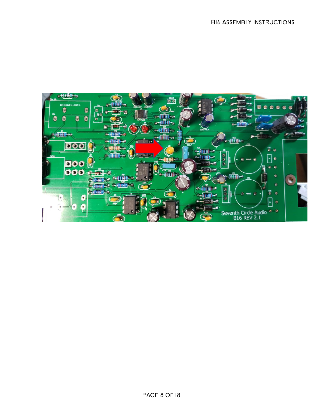
8. Install the ceramic, yellow capacitors. These capacitors are not polarized and can be
installed in either direction, but pay close attention to the capacitor markings! These
parts look alike but they are not interchangeable. Putting one in the wrong spot will not
prevent the compressor from passing signal, but it can seriously impair its performance!
9. Install the film capacitors at C16 and C21. These parts are not polarized and can be
installed in either direction, but pay close attention to the capacitor markings!

10. Install LEDs D4 and D5. LEDs are polarized and must be installed the right way
around! Install the long lead opposite the flat side of the silkscreen outline.
11. Add blue EMI filters L1 through L6. These parts are not polarized and can be installed in
either direction.
12. Add tantalum capacitor C10. Electrolytic capacitors are polarized and must be
installed the right way around! Be absolutely sure to observe the correct polarity when
installing these parts. The positive lead is marked with a colored stripe. The positive
pad on the circuit board is marked with a small "+" sign.
13. Install the aluminum electrolytic capacitors now. Electrolytic capacitors are polarized
and must be installed the right way around! Be absolutely sure to observe the correct
polarity when installing these parts. The negative leads of the electrolytic caps are
marked with a colored stripe. The positive pads on the circuit board are marked with a
small "+" sign.
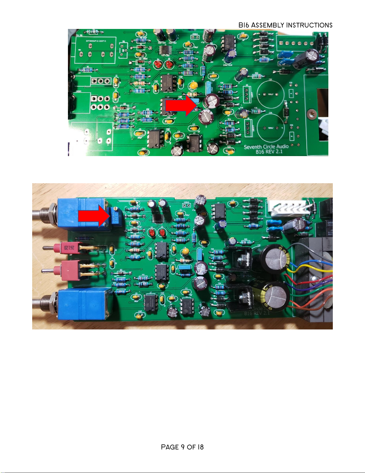
14. Attach trim potentiometer R8.
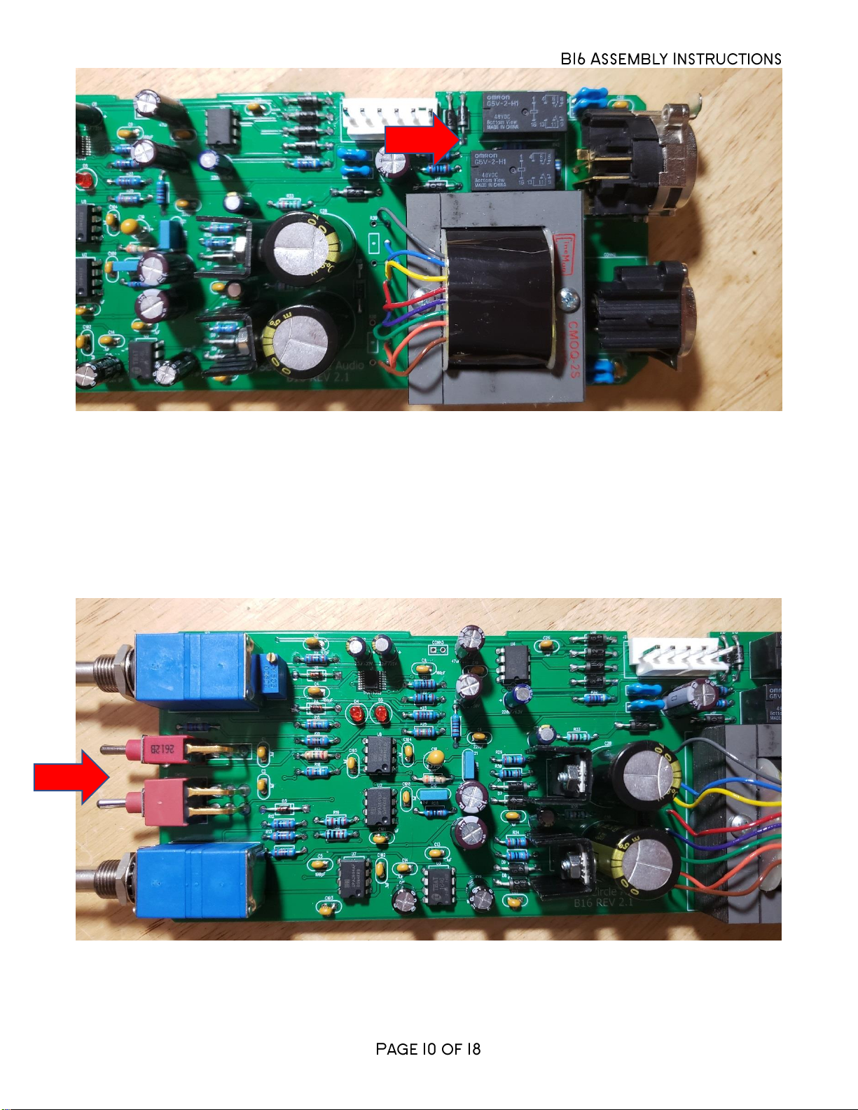
15. Install relays RLY1 and RLY2.
16. Carefully mount the toggle switches SW1 and SW201. Be sure they're seated flat on the
board before soldering the leads. You may find it easier to solder the first lead of each
switch while the board is component side up.
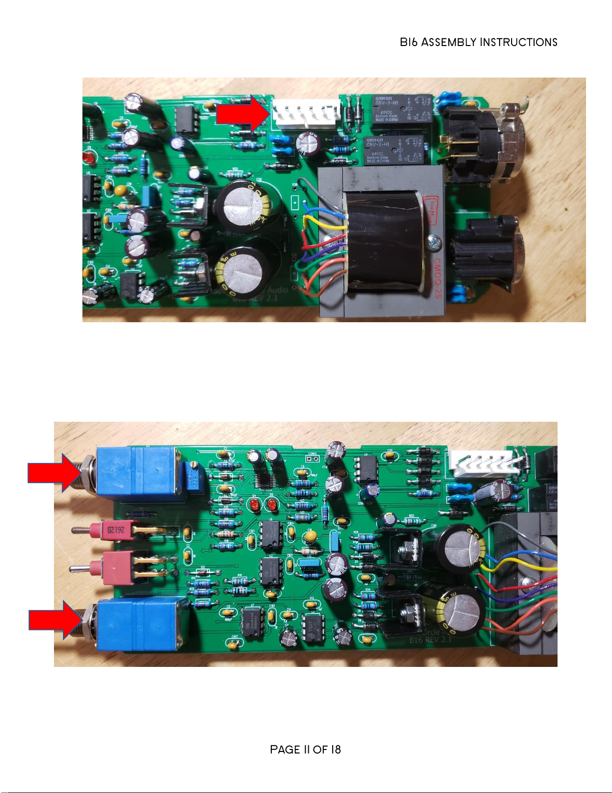
17. Add J2, the MOLEX power connector. Be sure to orient it as shown, with the locking tab
away from the edge of the board.
18. Attach panel control potentiometers R1 and R4. Make sure the controls are seated as
flat to the board as possible before soldering the leads.
19. Add CONN1 and CONN2 to the board. Make sure they’re fully seated before soldering.

20. Using the hardware supplied, attach heat sinks to U5 and U6 and solder them in place.
Make sure to install the regulators correctly! These parts are not the same and are
not interchangeable.
21. Install the bulk filter capacitors C17 and C21. Push them in firmly until they are fully
seated against the board. Again, electrolytic capacitors are polarized and must be
installed the right way around! Be absolutely sure to observe the correct polarity when
installing these parts.

22. Check your work carefully up to this point. Don’t install the other ICs yet.
Initial Power-Up and Testing.
23. Again, carefully check your work for solder bridges and open or poor joints. Make sure
you've got the right resistors in the right locations. Make absolutely sure you've got all
the polarized parts soldered in the right way around! Double check to make sure you
haven’t inadvertently swapped the voltage regulators. Fix any problems before
continuing.
24. Just to make sure you haven't created any blatant shorts, measure the resistance
between pins 1 and 2 of J2. Do the same for pins 3 and 2. If you measure a steady
resistance of less than 100 ohms, don't apply power. Carefully check your work until you
find that short.
25. Connect the PS04 power supply to the board using a WH01 wiring harness. Attach the
connectors so the locking ramps engage. Don’t connect the harness backwards! Set
your DMM to measure DC voltages of 18V or greater and apply power. Connect the
negative meter probe to J2, pin 2 or any connection labeled PGND. Connect the positive
meter probe to the +18V pin 8 shown below. You should measure very close to +18V.
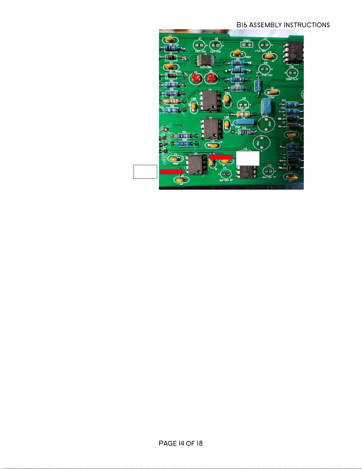
26. With the negative probe still at PGND, measure the voltage the –18V pin 4 shown above.
You should measure very close to -18V.
27. Set your DMM to measure DC voltages of 50V or greater. Center toggle switch SW1.
With the negative probe of your DMM connected to PGND, you should measure about
+47V at the anodes of D17 and D18.
28. Flip SW1 to the right and measure the voltage at the anode of D17. You should see 0V.
29. Flip SW1 to the left and measure the voltage at the anode of D18. You should see 0V.
30. If the voltages measured in the previous steps are off by more than 1V, you have
problems. Don’t proceed until you’ve found them! Possible things to check are incorrectly
installed diodes, especially D6 through D9, D14 through D18, backwards caps at C22,
C24, C25, C29, and C31, or shorts around U5 and U6.
31. When you’re certain that the voltage regulators are working, disconnect the power and
install U2-U4 and U7-U8. Be sure to handle the ICs in a static safe manner! Pay
close attention to the IC markings! Align the notch on the IC with the notch on the
silkscreen outline! If you’d like the option of easily swapping or replacing the ICs, now
is the time to add sockets. Sockets are optional and are not included in the kit.
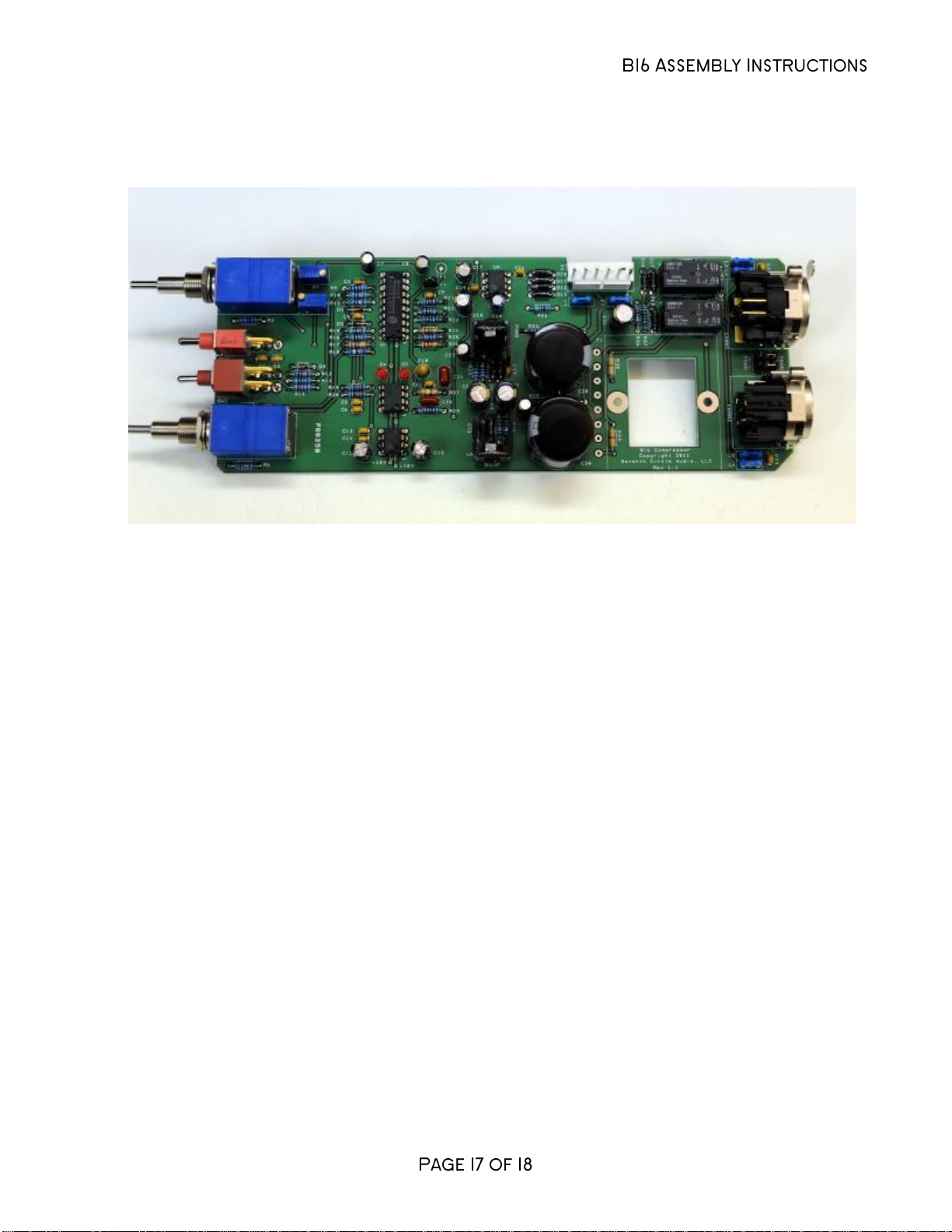
32. If you have a few empty spaces in your chassis, you may find the next steps easier with
the module installed and the front panel attached. It can also be done outside of the
chassis completely.
As++18V
As+-18V
33. Center SW1, the top toggle switch, and throw SW201, the bottom toggle switch, to the
right.
34. Connect the power and apply a 1 kHz signal to the input of the B16. Adjust the signal
generator output level to -10dBu. Connect the B16 output to a level meter.
35. Attach all four knobs by turning them fully
clockwise and tightening the set screws. The
output level should be in the neighborhood of
+15dBu.

36. Center the Makeup Gain (bottom, inner)
control.
37. Throw SW1 to the right (bypass) and observe the change in level on your meter.
Adjust the gain trim pot R8 so that the output level does not change between the center
and right switch positions on SW1.
38. Congratulations! You've got a working B16 compressor.
Options
1. DIP sockets may be used at U1-U4 and U7-U8 to allow for easy substitution of ICs. If you
decide to install sockets, high quality, low-profile machined-pin types are recommended.
Keep in mind that sockets may cause reliability issues in the very long term. IC Sockets
are optional and not included with the kit.
2. The B16 can be ordered with an optional output transformer. If you’re installing a
transformer, remove (or do not install) the 0R jumpers at R38 and R39. Be sure to install
spacers between the board and the transformer.
3. B16s can be linked in stereo pairs by connecting the CONN3 pad (either pad, they are
shorted together) on adjacent modules. Simply solder a jumper directly between the
modules. You can break the stereo link by removing the jumper at CONN3 on either
board. Jumpers must be installed at CONN3 on both linked modules to complete the link
circuit.
In Use
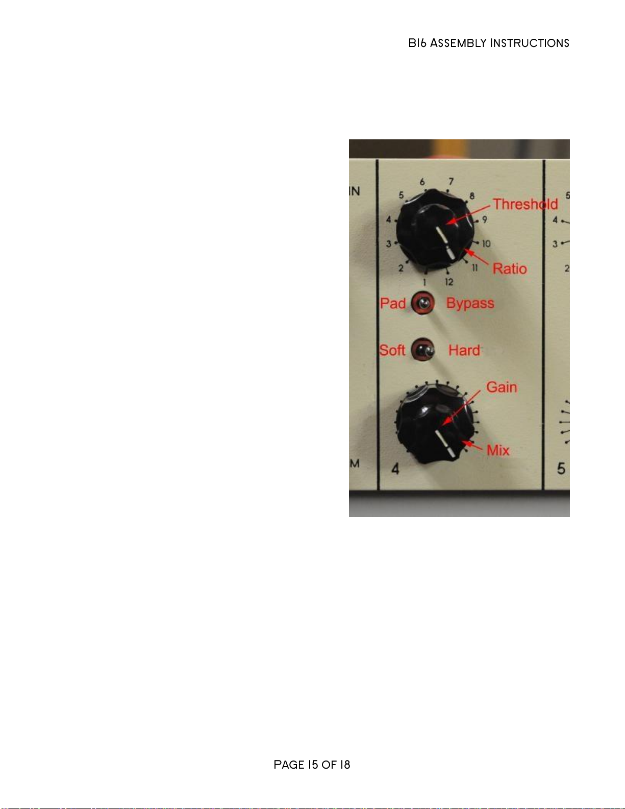
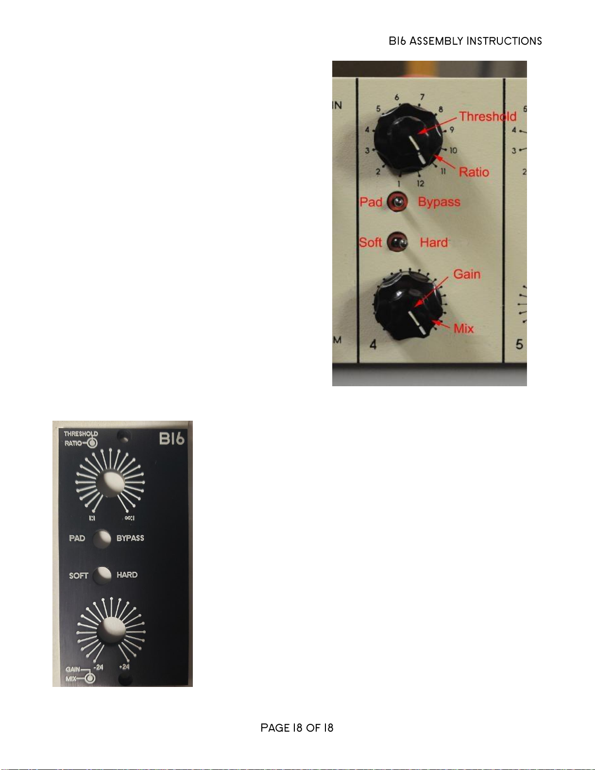
1. Compression Ratio –Adjustable from 1:1 (no
compression) to infinite (hard limiting.) The
ratio increases as the knob is turned clockwise,
so maximum compression occurs with the
control fully clockwise.
2. Threshold –Controls level where compression
starts. Signals below the threshold level are
not affected. The threshold level increases as
the knob is turned clockwise, so maximum
compression occurs with the control fully
counter-clockwise.
3. Makeup Gain –Adjusts gain applied to the
signal independent of compression. Gain
range is +/-24dB.
4. Mix –Allows a mix of direct and compressed
signal. Maximum counter-clockwise is fully
“dry”, maximum clockwise is fully “wet”.
5. SW1 –Left, 6 dB pad, Centered, normal
operation, Right, hard bypass
6. SW201 –Left, soft knee, Right, hard knee
Popular Air Compressor manuals by other brands


Metabo HPT
Metabo HPT EC 2610E Instruction manual and safety instructions

CMi
CMi C-LK 262/50/8 operating instructions

Clarke
Clarke CSC1000 Operating and maintenance instructions

Ozito
Ozito PXC PXOFCS-636 instruction manual

AllTrade
AllTrade 835408 instruction manual

Ryobi
Ryobi RA-ACDDU1840 Operator's manual