Severn Trent Capital Controls CI1000B User manual

1
Capital Controls®
Cl1000B
Bufferless Residual Analyser
90-1024
Operation and Maintenance Manual
Part no: 04-1008-E
Issue: Aug 2004
210.6350.9

2
These instructions describe the installation, operation and maintenance of the subject equipment. Failure to strictly
follow these instructions can lead to an equipment rupture that may cause significant property damage, severe
personal injury and even death. If you do not understand these instructions, please call Severn Trent Water
Purification for clarification before commencing any work at 215-997-4000 and ask for a Field Service Manager.
Severn Trent Water Purification, Inc. reserves the rights to make engineering refinements that may not be described
herein. It is the responsibility of the installer to contact Severn Trent Water Purification, Inc. for information that
cannot be answered specifically by these instructions.
Any customer request to alter or reduce the design safeguards incorporated into Severn Trent Water
Purification equipment is conditioned on the customer absolving Severn Trent Water Purification from any
consequences of such a decision.
Severn Trent Water Purification has developed the recommended installation, operating and maintenance
procedures with careful attention to safety. In addition to instruction/operating manuals, all instructions given on
labels or attached tags should be followed. Regardless of these efforts, it is not possible to eliminate all hazards
from the equipment or foresee every possible hazard that may occur. It is the responsibility of the installer to ensure
that the recommended installation instructions are followed. It is the responsibility of the user to ensure that the
recommended operating and maintenance instructions are followed. Severn Trent Water Purification, Inc. cannot be
responsible deviations from the recommended instructions that may result in a hazardous or unsafe condition.
Severn Trent Water Purification, Inc. cannot be responsible for the overall system design of which our equipment
may be an integral part of or any unauthorized modifications to the equipment made by any party other that Severn
Trent Water Purification, Inc.
Severn Trent Water Purification, Inc. takes all reasonable precautions in packaging the equipment to prevent
shipping damage. Carefully inspect each item and report damages immediately to the shipping agent involved for
equipment shipped “F.O.B. Colmar” or to Severn Trent Water Purification for equipment shipped “F.O.B Jobsite”.
Do not install damaged equipment.
SEVERN TRENT SERVICES, COLMAR OPERATIONS
COLMAR, PENNSYLVANIA, USA
IS ISO 9001: 2000 CERTIFIED
Use only in accordance with Instruction Manual
PROTECTIVE GROUND (EARTH) TERMINAL
WARNING: HAZARDOUS VOLTAGES
WARNING: WARNING, AS USED IN THIS MANUAL, IS DEFINED AS A CONDITION OR
PRACTICE WHICH COULD RESULT IN PERSONAL INJURY OR LOSS OF LIFE.
CAUTION: CAUTION, AS USED IN THIS MANUAL, IS DEFINED AS A CONDITION OR
PRACTICE WHICH COULD RESULT IN DAMAGE TO OR DESTRUCTION OF THE EQUIPMENT
OR APPARATUS UNDER TEST.

3
Table of Contents
SAFETY...................................................................................................................................................4
1 INTRODUCTION......................................................................................................................................5
1.1 General Description..................................................................................................................5
1.2 Glossary....................................................................................................................................5
1.3 Definitions.................................................................................................................................5
1.4 Specifications ...........................................................................................................................6
1.5 Principle of Operation...............................................................................................................7
1.6 Chlorine Chemistry.................................................................................................................10
1.7 Galvanic Cell Theory..............................................................................................................11
2 INSTALLATION .....................................................................................................................................12
2.1 General...................................................................................................................................12
2.2 Mounting.................................................................................................................................13
2.3 Hydraulic Connections (Wall Panel Only) ..............................................................................13
2.4 Electrical.................................................................................................................................14
3 STARTUP...............................................................................................................................................17
3.1 Conditioning the Analyser.......................................................................................................17
3.2 Programming the Monitor.......................................................................................................17
3.3 Set-up.....................................................................................................................................18
3.4 Calibration...............................................................................................................................30
4 TEMPERATURE CALIBRATION ..........................................................................................................33
5 DIAGNOSTICS.......................................................................................................................................34
6 GRAPHICAL TRENDING CAPABILITIES ............................................................................................36
7 SERVICE................................................................................................................................................38
7.1 Overview.................................................................................................................................38
7.2 Cleaning..................................................................................................................................38
7.3 Equipment Service .................................................................................................................39
7.4 Recommended Preventive Maintenance Schedule ...............................................................43
8 TROUBLESHOOTING............................................................................................................................44
FIGURES
1 Cl1000 Residual Analyser Components....................................................................................7
2 Flow Diagram.............................................................................................................................8
3 Sample Cell Assembly...............................................................................................................8
4 Flow Cell Assembly ...................................................................................................................9
5 Dissociation Curve...................................................................................................................10
6 Variation with pH .....................................................................................................................10
7 Galvanic Cell............................................................................................................................11
8 Dimensions..............................................................................................................................13
9 Sample Line Taps....................................................................................................................14
10 Four Residual Analyser Sample System Examples................................................................15
11 Wiring Diagram........................................................................................................................16
12 Main Screen.............................................................................................................................18
13 Trend Screen...........................................................................................................................36
14 X-Axis Screen..........................................................................................................................36
15 Analysis Screen.......................................................................................................................37
EC DECLARATION OF CONFORMITY…………………………………………………………………………45
AMMENDMENT RECORD SHEET……………………………………………………………………………....46

4
Safety
The recommended operating procedures have been designed with careful attention to safety. Severn
Trent Services has made formal safety reviews of the initial design and any subsequent changes. This
procedure is followed for all new products and covers areas in addition to those included in applicable
safety standards. Regardless of these efforts, it is not possible to eliminate all hazards from the test
equipment or to foresee every possible hazard that may occur. It is therefore essential that the user, in
addition to following the safety rules in this manual, also carefully consider all safety aspects of the test
before proceeding. Safety is the responsibility of the user.
This equipment has been designed in accordance with safety specifications IEC 1010-1 and ANSI/ISA
S82.01 and meets the requirements for Class I, Installation Category II equipment.
Observe the following safety precautions:
Observe all safety warnings marked on the equipment. These warnings identify areas of
immediate hazard, which could result in personal injury, or loss of life.
Do not use this equipment for any purpose other than described in this manual.
Disconnect power to the Cl1000B prior to making any terminal connections within the monitor
enclosure.
Do not operate the equipment with the electronics enclosure open for an extended period of time.
Operation without the protective instrument covers presents an electric shock hazard.
Use all practical safety precautions to prevent contact with energized parts of the equipment and
related circuits.
Use the recommended connection procedures described in Section 2 of this manual.
The Cl1000B Residual Analyser operates from a single-phase power source. A three-wire power cord is
required for power connection. The voltage to ground from either pole of the power source must not
exceed the maximum rated operating voltage, 240 VAC. Before making connection to the power source,
determine that the voltage of the power source is correct. The power source must have a fuse or circuit
breaker, recommended rating: 2 Amp anti surge MCB.
Severn Trent Services recommends that qualified personnel install and connect the instrument.
Component replacement and internal adjustments must be made by qualified service personnel only.

5
1 INTRODUCTION
1.1 General Description
The Capital Controls® Cl1000B Residual Analyser is an amperometric instrument designed to
continuously analyse residual levels of free chlorine or other oxidants in water, or aqueous liquids
without the use of a buffer reagent.
1.2 Glossary
1.2.1 Physical
mg/l Milligrams per liter
µg/l Micrograms per liter
ppm Parts per million (in water same as mg/l)
ppb Parts per billion (in water same as µg/l)
ml/min Milliliters per minute (as in sample flow)
1.2.2 Electronic
PC Personal computer
PSU Power Supply Unit
I/O Input and output
RS232 Standard form of serial communications, used in modems and faxes, etc.
RS485 Similar protocol to RS232 but uses different hardware to allow
communication over a long distance
PLC Programmable Logic Controller - a computer used for distributed control
RTD Resistive Temperature Detector
SCADA Supervisory Control And Data Acquisition - a plant control system
1.3 Definitions
Menu - The series of selections boxed and arranged vertically on the left side of the screen.
Return - The Return key will always return the user to the previous screen. When changing
values within a screen, pressing the Return key [ ]stores the new value.
Default - Pressing the Default key will restore factory settings.
Restore - Pressing the Restore key will restore the parameter to the previous setting or value.
Cold Start - A procedure for fully initialising the microprocessor.
Locked Up - A condition where the monitor appears to be completely frozen. This is usually a
microprocessor condition. This is rarely a permanent condition and can usually be cured with a
cold start.

6
1.4 Specifications
1.4.1 General
Quality Standards: Severn Trent Water Purification Ltd is ISO 9001:2000 Certified
Compliance: CE, UL (optional)
Residual Measured:
Free Chlorine
Bromine
Iodine
(Consult Factory for other oxidants)
Instrument Range: Automatic ranging from 0 - 60 (mg/l)
Display: 4" x 3", dot-matrix, graphical display
Data Logging: Up to 28 days; previous 7 days; previous 24 hours
Resolution: 0.001 mg/l for below 10 mg/l, 0.01 for 10 - 60 mg/l
Sensitivity: 0.001 mg/l or 1 ppb
Residual Units (Configurable): mg/l or ppm, µg/l or ppb
Analyser Location: As close as possible to sample point
Speed of Response: Twelve (12) seconds from sample entry to display indication. 90%
of full-scale response within 1½ to 2 minutes.
Ambient Temperature: 32°F-140°F (0°C-60°C)
Languages: English (for other languages, consult factory)
1.4.2 Electrical
Power Requirements: Automatic power recognition from 85-264 Vac, 47-63 Hz, single
phase; or 24 Vdc
Power Consumption: 50 Watts
Fuse: 2.5 amp, fast blow, 250 Vac, 5 mm x 20 mm
Output Signal: Dual 4-20 mAdc, 0-20 mAdc, 0 -10 mAdc, isolated into 1000 ohms max.
Relay Contacts: Six. Each relay is independently configurable to be high, low, attention,
or fail. The fail relay can be set by a hardware jumper to indicate a power failure. There
are also settings for hysteresis, delay and action. Alarm contacts 5A @ 240 Vac resistive.
1.4.3 Sample Data:
Sample Flow: 150 ml/min at 5 psig minimum (10 psig maximum)
Sample Temp: 32°F-120°F (0°-50°C)
Sample Supply: Continuous. Where sample interruption may be required, provision must
be made to keep electrodes wet.
Sample Limitations: Samples containing particles 100 microns (0.004 inches) in
diameter and larger may require pre-filtration. Samples containing high concentrations of
metal ions, oils, or certain corrosion inhibitors may effect analyser operation. Consult
factory for specific applications.
E.g. A hardness of 50ppm per 1ppm chlorine is required to supply sufficient proton
donors (eg 0.2ppm chlorine requires 10ppm hardness).
Accuracy: 1% of reading or ±0.002 mg/l, whichever is greater for residual levels below 20
mg/l; 5% of reading for residual levels 20-60 mg/l (see sample limitations).

7
1.4.4 Instrument Data:
Electronics Enclosure: NEMA 4X
Electrodes:
Cathode (measuring) - Gold
Anode (counter) - Copper
Reference - Ag/AgCl reference electrode
Shipping Weight: 22 lbs (10 kg)
Dimensions: 12.9" (w) x 12.9" (h) x 7.7" (d) (330 mm x 330 mm x 195 mm)
1.5 Principle of Operation
A sample of liquid is delivered to the sample inlet chamber at an approximate rate of 150
ml/minute. The excess overflows to drain. The flow to the analyser is monitored by a unique
infrared flow detection system (Reference Figure 2).
A 100 Ohm RTD is located in the inlet chamber, to allow for temperature compensations. The
sample then passes through an annular space between two electrodes in the sensing cell
assembly. (Reference Figure 3) As it passes, a small DC current is generated in direct linear
proportion to the amount of residual present in the sample. A third, reference electrode, located
upstream of the sensing cell, establishes a constant potential on the working electrode to provide
an accurate stable residual indication. The residual value is displayed on the dot-matrix display in
4 1/2-digit or graphical format. Residual units of ppb, µg/l, mg/l or ppm are user-selectable.
Figure 1 – Cl1000B Residual Analyser – Components

8
Figure 2 – Flow Diagram
Figure 3 – Analyser Cell Assembly
The surfaces of both electrodes in the sensing cell assembly are kept clean by the continuous
action of PVC spheres agitated by a motor-driven rotating striker assembly. This constant cleaning
minimizes signal drift and recalibration, and provides an accurate residual measurement. The
sensing cell assembly, including stepper motor, motor cable with quick-disconnect for connection
to electronics enclosure, cathode, anode, PVC spheres, and agitator assembly can be removed
from the wet-end of the analyser as a single assembly, for easy maintenance. A 100-ohm RTD
compensates for temperature variations.

9
Figure 4 – Flow Cell Assembly
The sample tap assembly (fig 4, 19) is an optional extra.

10
1.6 Chlorine Chemistry
As chlorine dissolves in water, hypochlorous acid (HOCl) and hydrochloric acid (HCl) are formed
according to the following equation:
Cl2+ H2O →HOCl + HCl
Hypochlorous acid may be formed with the addition of hypochlorite [e.g. sodium hypochlorite
(NaOCl) or calcium hypochlorite (Ca(OCl)2)] to water.
NaOCl + H2O →HOCl + Na++ OH-
Ca(OCl)2+ 2H2O →2HOCl + Ca2+ + 2OH-
Hypochlorous acid is a weak acid, only partially dissociating into hydrogen and hypochlorite ions.
The sum of hypochlorous acid and hypochlorite ion in solution is called “free available chlorine".
HOCl →H++ OCl-
The degree of dissociation (or ionization) of hypochlorous acid is
affected by the availability of protons. Historically it was thought
that successful measurement of residual chlorine required a low
pH. In a zero hardness water with decreasing pH, the degree of
dissociation of hypochlorous acid decreases. Below
a pH of 5.0, the dissociation of hypochlorous acid is virtually zero,
regardless of temperature. As temperature increases or
decreases, the dissociation curve shifts along the pH axis. See
Figure 5.
This is only true if there is no other source of protons, except for
the low pH. For the electroreduction of chlorine there must be a
sufficient supply of protons, which can be provided by the natural
hardness in water. 50ppm of hardness (as CaCO3) is required per
1.0ppm of free chlorine to be measured.
As long as a sufficient supply of protons is available (hardness),
and with temperature compensation, the chlorine residual is
measurable at any pH below 9. See figure 6.
Figure 5 – Dissociation Curve
Figure 6 – Cl1000B Residual measurement on a sample with a constant residual, but varying pH
0
0.05
0.1
0.15
0.2
0.25
0.3
4.5 5.5 6.5 7.5 8.5 9.5
pH
Cl2 (mg/l)

11
SOLUTION
Cu° Cu + 2e
++ - HOCI + 2e
-
+ -
CI + OH
CATHODEANODE
1.7 Galvanic Cell Theory
Water, in pure form, is relatively nonconductive, but addition of an ionizing species (e.g. salt)
allows current to pass. The greater the concentration of ions in solution, the greater the
conductance of the solution.
If two electrodes are immersed in an ion containing solution, a chemical species capable of being
reduced (gaining electrons) can move toward the cathode where electrons are transferred from
the cathode to the reducible species, resulting in a cathodic current.
At the same time, an oxidation reaction (where an oxidizable species loses electrons) occurs at
the anode. Electrons are then transferred to the anode, producing an anodic current.
As the reaction occurs at the cathode, the
concentration of the reducible species at the
cathode drops. In response to the resultant concentration
gradient created, more of the reducible species moves
toward the cathode. This is referred to as diffusion. The
speed of movement of the reducible species toward the
cathode is called the rate of arrival.
The rate that the reducible species arrives at the cathode is
dependent on its concentration. As the concentration
increases the diffusion to the cathode increases, which
increases the current.
The current is also affected by temperature. With elevated
temperatures, diffusion increases. Most systems
compensate for temperature in some fashion.
Figure 7 – Galvanic Cell
If the electrodes are made of two (selected) dissimilar metals and the proper conditions exist with
regard to solution composition, current can be produced by simply connecting (shorting) the
electrodes. This type of cell is called a galvanic cell.
In a galvanic cell, a change in concentration is detected by measuring the change in current
flowing through the cell (Reference Figure 7). The cell current responds proportionally to changes
in concentration.
The cathode in the galvanic cell used in the Cl1000B Chlorine Analyser is gold. When
hypochlorous acid (or hypochlorite ion) is present in solution, electrons are exchanged at the
cathode surface and chloride ions are produced.
HOCl + 2e-→Cl-+ OH-
The anode is copper. As electrons are exchanged, an oxide product remains on the anode.
Because of this, an abrasion mechanism (constant stirring of cleaning spheres) is incorporated to
strip the oxide product off the metal surface. Since copper is consumed in the process, the term
sacrificial anode is applied to the copper electrode.
In addition to the gold cathode and copper anode, the Cl1000B includes a third, reference
electrode. The reference electrode fixes the potential across the cathode to provide an accurate,
stable residual indication.
Current flow in the amperometric cell may be affected by large changes in pH.
Temperature compensation circuitry is employed to counter the effects of diffusion and other
factors that are affected by temperature.
Copper Gold

12
2 INSTALLATION
2.1 General
The Capital Controls® Cl1000B Residual Analyser is designed for a multitude of applications. This
instrument will provide unparalleled accuracy for drinking water, cooling water, beverage,
industrial effluent, RO membrane, and process control applications or any application where
highly accurate chlorine detection and control are necessary. The tasks described in this section
require that individuals be technically knowledgeable and aware of proper safety procedures.
Individuals must adhere to all applicable electrical and plumbing codes.
2.1.1 Unpacking
Remove the instrument from its packing container and carefully inspect each item and
report damages immediately. Be sure that the following items were included in the carton:
Capital Controls® Cl1000B Residual Analyser
Electronics and Wet-End Mounted on a PVC panel
Reference electrode
Sample flowmeter
Sample Tubing
Drain Tubing
Sample Tubing Connectors (1/4" MNPT x hose)
Instruction Manual
2.1.2 Environmental Requirements
The instrument is designed for general duty indoor installation. Outdoor installation is
possible if the instrument is shielded from dripping water and not mounted in direct
sunlight. Ambient temperatures should range from 32°F to 140°F (0°C to 60°C) with
sample temperatures from 32°F to 120°F (0°C to 50°C).
2.1.3 Location
In order to obtain optimum performance from the Capital Controls® Cl1000B Residual
Analyser, selection of a good, representative sampling point is critical. If a sampling point
is too close to the chlorine feed, inadequate mixing, or incomplete chlorine/sample
reaction may occur. The sampling point should be where the sample and chlorine is
reacted and mixed thoroughly so the analyser is indicating the representative residual
chlorine being carried throughout the water system.
All residual analysers should be located as close to the sampling point as possible to
reduce sample lag time. Sampling lines should be run with small diameter tubing to
minimize the lag time.
The electronics enclosures of the Capital Controls® Cl1000B Residual Analysers are
rated NEMA 4X and are designed to protect the electronics from typical conditions in
water treatment plant or industrial facilities.

13
Figure 8 – Dimensions
2.2 Mounting
2.2.1 Wall Panel
Dimensional drawings are given to aid installation and to determine the position of
mounting holes. See Figure 8.
a. Position the analyser panel on a wall at eye level and as close as possible to the
sample source.
b. Secure with four (4) each x 6mm bolts, leveling the analyser before securing.
c. Use a spirit-level to level the instrument. This ensures that the sample liquid will
flow correctly through the instrument.
2.3 Hydraulic Connections (Wall Panel Only)
2.3.1 Procedure
a. Connect a length of 8mm (5/16”) drain hose to the drain outlet on the analyser.
Route the hose to maintain a gravity fed drain (downward slope).
NOTE: the drain connection is also the sample overflow connection and may be
recycled into the sample stream. Refer to Figure 1.
b. Connect a length of 5/16" sample supply tubing to the source using the 1/4" NPT
connector. Connect the other end of the sample supply tubing to the analyser
inlet. The maximum desired pressure for the flow is 10 psig (0.6 bar). The sample
tubing is rated to 55 psig (3.8 bar).
c. A sample tap assembly (figure 4, 18) attaching to the sample drain, is available as
an optional extra.
14
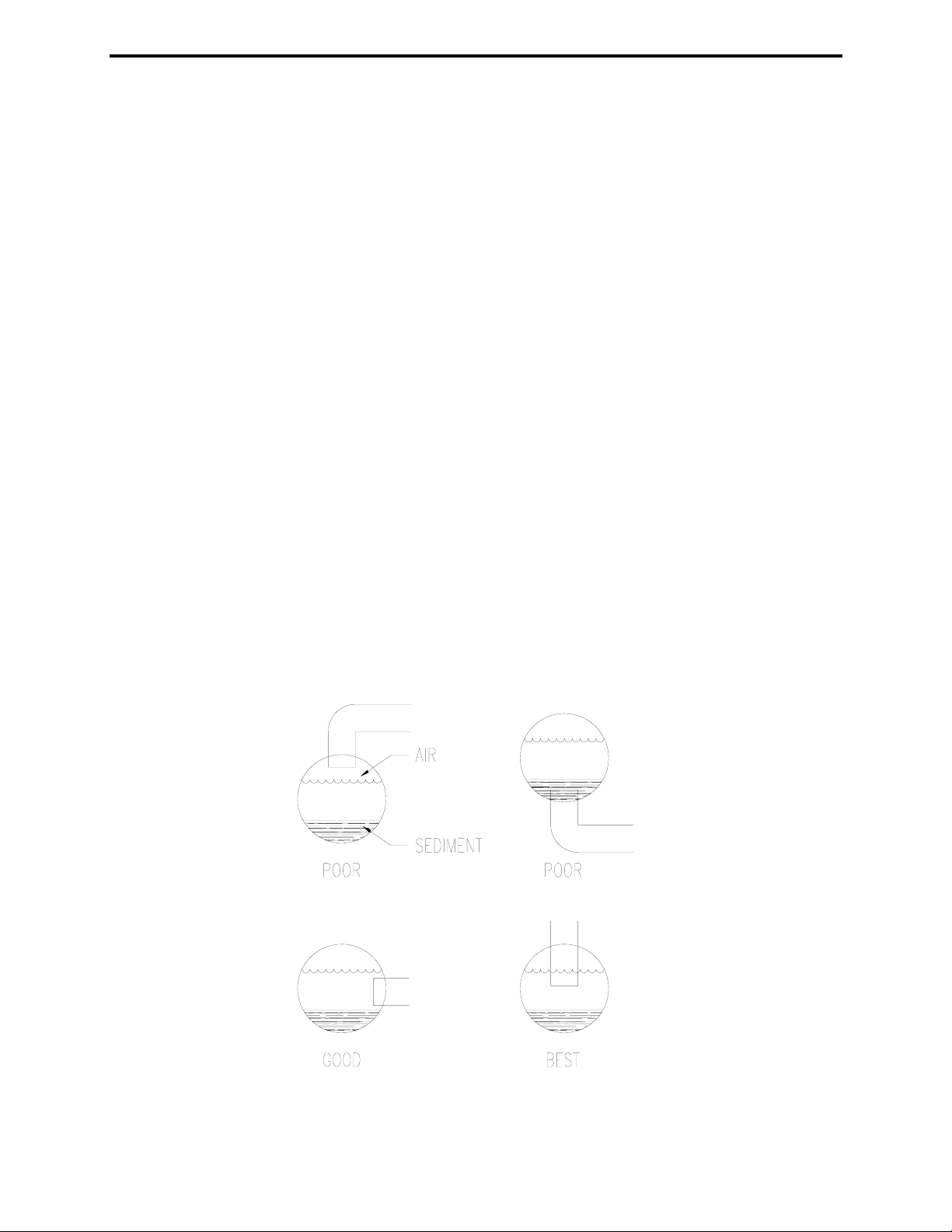
2.3.2 Sample Line Taps
Sample line taps into larger pipes should be installed to minimise the chances of air
bubbles or sediment entering the analyser. A tap should project into the centre of the line.
Refer to Figure 9.
2.3.3 Sample Flow
A typical installation may require a sample pump if the pressure is low and/or a Y-strainer
to remove any particulates. There may also be a need for a pressure reducing valve if
the sample pressure is too high or the sample pump needs to be regulated. Refer to
Figure 10.
2.4 Electrical
WARNING: FAILURE TO DISCONNECT POWER TO THE Cl1000 RESIDUAL ANALYSER
PRIOR TO ACCESSING THE INTERIOR OF THE ELECTRONICS ENCLOSURE MAY
RESULT IN SERIOUS PERSONAL HAZARD FROM EXPOSURE TO LETHAL VOLTAGES.
CAUTION: ALL WIRING MUST COMPLY WITH APPLICABLE LOCAL AND NATIONAL
ELECTRICAL CODES.
2.4.1 Wall Panel Mounted Conduit Connections - Refer to Figure 11
a. Remove four (4) screws securing the terminal cover located below the computer
screen.
WARNING: POWER FOR THE UNIT SHOULD BE SUPPLIED FROM FUSED
DISCONNECT (2 Amp anti surge MCB recommended). THIS DISCONNECT
SHOULD BE LOCATED IN CLOSE PROXIMITY TO THE UNIT AND SHOULD
BE LABELED AS THE DISCONNECT FOR THE UNIT. WIRING SHOULD
FOLLOW ALL APPLICABLE LOCAL ELECTRICAL CODES AND
REGULATIONS.
Figure 9 – Sample Line Taps

15
Figure 10 – Four (4) Residual Analyser Sample System Examples
b. Connect the power wiring to terminals labeled L1, N and ground.
d. Connect current output and alarm contacts.
NOTE: The green relay terminal strips ‘snap’ out to allow more room for cable
connection. Pull gently on the green terminal strip to remove, connect electrical
cables, and ‘snap’ terminal strip back in place on the terminal board.
CAUTION: DO NOT RUN LINE VOLTAGE AND LOW LEVEL SIGNAL
VOLTAGE IN THE SAME CONDUIT.
e. Replace terminal cover and secure with four (4) screws

16
Figure 11 – Wiring Diagram

17
3 STARTUP
3.1 Conditioning the Analyser
WARNING: FAILURE TO DISCONNECT POWER TO THE Cl1000 RESIDUAL ANALYSER
PRIOR TO ACCESSING THE INTERIOR OF THE ELECTRONICS ENCLOSURE MAY RESULT
IN SERIOUS PERSONAL HAZARD FROM EXPOSURE TO LETHAL VOLTAGES.
3.1.1 Remove the soaker teat from the measuring end of the electrode and place the reference
electrode in the reference electrode reservoir (See Figure 2).
Note: Retain the soaker teat for future use.
CAUTION: REFERENCE ELECTRODE MUST REMAIN IN REFERENCE ELECTRODE
RESERVOIR AT ALL TIMES DURING THE OPERATION OF THE Cl1000. REMOVAL
OF THE REFERENCE ELECTRODE FROM THE RESERVOIR DURING OPERATION
MAY CAUSE ERRONEOUS READING AND LEAD TO EQUIPMENT DAMAGE.
3.1.2 Start the sample water flow at approximately 150 ml/minute. If using the data from the
built in flow cell make sure the flow rate displayed in the diagnostics screens is at least
500mls/minute (the flow cell is used to detect flow/no flow and the actual flow rate
displayed tends to under read the actual real flow rate.
Water must be flowing over the overflow weir in the sample inlet chamber to drain.
3.1.3 If the system requires occasional cutoff, provisions must be made to keep the electrodes
wet.
3.1.4 Sampling from a pressurized source may require a pressure reducing valve to hold the
flow constant. Maximum desired pressure is 10 psig (0.6 bar).
3.1.5 If sampling from turbid water, a flushing Y-strainer is necessary to prevent clogging of the
sample line. Other types of filters are not recommended.
3.1.6 Connect power to the analyser terminals. (See Section 2.4)
3.1.7 Switch on the power to the analyser at the isolation point.
3.1.8 Turn ON the power switch on the analyser. To clear the analyser memory and return the
set up parameters to their factory defaults (perform a cold start), hold down the two left
keys on the keypad while you turn the analyser power switch ON.
NOTE: The analyser will take approximately 45 seconds to ‘boot up’.
3.1.9 Go to the analyser ‘Set Up’ to adjust any of the preconfigured screen settings on the
monitor. See Section 3.3.
3.1.10 For maximum accuracy the analyser requires a stabilisation time of up to 24 hours
however a result within ±10% is normally achieved within 1 hour. The analyser should be
run continuously, without interruption of power. Turning off the cell, even momentarily, will
require the appropriate stabilisation time upon restart. During operation, sample must be
feeding into the cell.
3.1.11 After stabilisation, calibration of the analyser may begin. See Section 3.4.
3.2 Programming the Monitor
All programmable options necessary for operation of the monitor are accessible through the four-
button keypad and display. To move from screen to screen, follow the instructions on the display.
From anywhere in the software, the [] key (far right key) will always return the monitor to the

18
previous screen. At factory default, the software is programmed to automatically return to the main
screen after 60 minutes without user interface.
3.2.1 Main Screen
The Main Screen is the default screen for viewing the residual value in digital format. The
residual value appears on the screen in four (4) x 1-inch high digits and a decimal; the
decimal place automatically shifts according to the residual value. The residual oxidant
and units (e.g. mg/l free Cl2) are displayed on this screen in smaller digits under the
residual value, and the current time and date are indicated at the top of the screen. The
software is programmed to automatically return to the main screen after 60 minutes
without user interface, unless the user is viewing the data in graphical format. From the
Main Screen, the user can initiate four selection options: Graphing, Calibration, Set Up, or
Diagnostics. If an error or alarm condition takes place, a warning message will appear
across the lower section of the screen, just above the user interface options.
Figure12 Main Screen
3.3 Set Up
The user set up screens are designed to allow for hardware and software adjustments to the
Cl1000 to configure the unit for site-specific operation. The following table summarises the user-
configurable options and the location of the screens for these adjustments:
Screen Name Screen Function Notes
Set Up Lists adjustable Set Up Parameters There are a total of 8 adjustable
parameters on the Set Up Screen (note
continuation arrows for additional options)
Buffer In the manual buffer adjustment mode,
this screen allows the user to adjust
the buffer feed rate.
No buffer used on Cl1000B
Therefore not used in Cl1000B
Buffer Setpoint Not used for Cl1000B
Setpoint Enter Not used for Cl1000B
Screen LCD settings, including screen
brightness, contrast and screen saver
are adjusted under this selection
Bright Allows user to adjust screen brightness
Contrast Allows user to adjust screen contrast
Lamp The lamp saver and timeout are
adjusted under this screen
Lamp Selection This screen allows the user to
configure the lamp to be always on, or
to go to low power after 10 minutes, 5
minutes, or 1 minute of inactivity. This
allows the user to adjust the life of the
lamp per operational requirements.
If the lamp is configured to go to low power
after a time period, any button press will
return the screen to the normal brightness.

19
Screen Name Screen Function Notes
Screen Timeout The software for the Cl1000 is
designed to return to the digital display
on the main screen after a period of
inactivity when the user is in any of the
Calibration, Set Up, or Diagnostic
screens. This screen allows the user to
set this time period at 60 minutes, or to
turn the screen timeout off.
If amperometric titration is being used to
confirm calibration of the instrument, the
screen timeout should be set at 60 minutes
to allow time for the calibration results.
Date Settings The current date and time can be
adjusted under this screen, along with
the date format
Time The current time is adjusted from this
screen. The current time is indicated
on the top line of every screen.
Date The current date is adjusted from this
screen. The current date is indicated
on the top line of every screen.
Date Format The current date, which appears on
the top line of every screen, can be
configured to appear in
month/day/year, day/month/year, or
year/month/day format.
Outputs The user configures the two mA output
signals and the alarm relays under this
selection
mA Output A The function (or range) and high and
low set points for mA Output Signal A
are configured under this selection
1. Each mA output signal is independently
configurable.
2. The mA outputs and relays are
configured under the Output Set Up
screens. These outputs can be tested
under the Diagnostics screen.
mA Output A
Function The value of mA Output Signal A can
be configured for 4-20 mA, 0-20 mA, or
0-10 mA from this screen
mA Output A
Low
Setting
The residual value for the low mA set
point for Output A is configured from
this screen.
mA Output A
High
Setting
The residual value for the high mA
setpoint for Output A is configured
from this screen
mA Output B The function (or range) and high and
low set points for mA Output Signal B
are configured under this selection

20
Screen Name Screen Function Notes
mA Output B
Function The value of mA Output Signal B can
be configured for 4-20 mA, 0-20 mA, or
0-10 mA under this screen
mA Output B Low
Setting The residual value for the low mA
setpoint for Output B is configured from
this screen.
mA Output B
High Setting The residual value for the high mA
setpoint for Output B is configured from
this screen
Relay Assignments The status (off, high, low, attention or
fail) of the six alarm relays and the
residual value to activate the alarm
relays are configured under this screen
selection
1. The actuation value of each relay
cannot be adjusted until the status of
the relay is changed to ‘high’ or ‘low’
2. A status of ‘attention’ will provide
indication when any one of a series
of errors activates the relay. These
include sample flow failure,
temperature probe failure, calibration
error or activation of a concentration
alarm (if set).
3. A fail alarm is generated for a
general failure of the intsrument or
for a power failure (set by a
hardware jumper) see fig. 10.
4. There are a total of six alarm
relays, each independently
configurable (note the continuation
arrows for additional options)
Relay 1 Status Relay 1 can be configured for high, low,
attention or fail, or can be turned off
Relay 1 Value If Relay 1 is configured for a ‘high’ or
‘low’ alarm, the residual value to
activate the alarm indication is adjusted
from this screen
Relay 2 Status Relay 2 can be configured for high, low,
fail or attention, or can be turned off
Relay 2 Value If Relay 2 is configured for a ‘high’ or
‘low’ alarm, the residual value to
activate the alarm indication is adjusted
from this screen
Relay 3 Status Relay 3 can be configured for high, low,
attention or fail, or can be turned off
Relay 3 Value If Relay 3 is configured for a ‘high’ or
‘low’ alarm, the residual value to
activate the alarm indication is adjusted
from this screen.
Relay 4 Status Relay 4 can be configured for high, low,
attention or fail, or can be turned off
Relay 4 Value If Relay 4 is configured for a ‘high’ or
‘low’ alarm, the residual value to
activate the alarm indication is adjusted
from this screen
Relay 5 Status Relay 5 can be configured for high, low,
attention or fail, or can be turned off
Table of contents
Popular Measuring Instrument manuals by other brands


Powercor
Powercor Sprint 200 reference guide

MULTISPAN
MULTISPAN PI 38 manual

MESSKO
MESSKO MLog IM50 operating instructions

Watts
Watts HF Scientific AccUView LED Ex installation instructions

METREL
METREL EurotestIM instruction manual

PCB Piezotronics
PCB Piezotronics IMI Sensors 621C40 Installation and operating manual