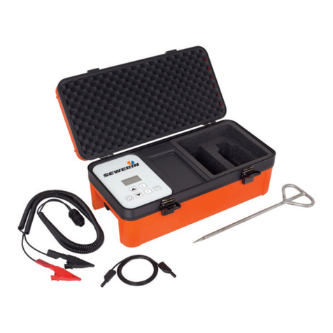
sewerin COMBIPHON CG 150 User manual

12.12.2023 a – 108797 – en
COMBIPHON®
CG 150 generator
Striker and stopper
Operating instructions

CG 150 generator
Fig. 1: CG 150 generator with an opened case
Fig. 2: Control panel
Control panel
Charging socket
Port for accessories
Display
ON/OFF key
Frequency keys
Pulse button
Arrow keys
●Up key
●Down key

CG 150 generator
Hz
Fig. 3: Display (here: during energising with striker)
Frequency
Striker
Signal strength
Charge
Signal behaviour

Illustration of warnings in this document
NOTICE!
Risk of damage to property.

Contents│ I
1 Introduction .............................................................................1
1.1 Information about this document...............................................1
1.2 Purpose.....................................................................................1
1.3 Intended use .............................................................................2
1.4 Safety information .....................................................................2
2 Product description ................................................................4
2.1 General .....................................................................................4
2.2 CG 150 generator .....................................................................4
2.2.1 Ports.......................................................................................4
2.2.2 Power supply..........................................................................4
2.2.3 Remote control.......................................................................5
2.3 Optional accessories.................................................................5
2.3.1 Striker.....................................................................................5
2.3.2 Stopper...................................................................................5
2.4 Settings for energising ..............................................................5
2.4.1 Frequencies ...........................................................................6
2.4.2 Signal strength .......................................................................6
2.4.3 Signal behaviour ....................................................................6
3 Energising pipes .....................................................................8
3.1 Switchingthegeneratoronando............................................8
3.2 Selecting a frequency................................................................8
3.3 Setting the signal strength.........................................................8
3.3.1 Signal strength of the striker ..................................................8
3.3.2 Signal strength of the stopper ................................................9
3.4 Selecting the signal behaviour of the striker .............................9
3.5 Energising using a striker..........................................................9
3.6 Energising using a stopper......................................................10
3.7 Using the remote control .........................................................12
3.7.1 Usingtheremotecontrolforthersttime ............................12
3.7.2 Pause function .....................................................................12
3.7.3 Setting the signal strength (striker only)...............................13
4 Maintenance ..........................................................................14
4.1 Charging the rechargeable battery..........................................14
4.2 Care ........................................................................................15
4.2.1 Cleaning the generator and striker.......................................15
4.2.2 Cleaning the stopper ............................................................15

II │Contents
4.2.3 Water in the case .................................................................17
4.2.4 Storage.................................................................................17
4.3 Servicing .................................................................................17
4.4 Troubleshooting.......................................................................17
4.4.1 Generator .............................................................................17
4.4.2 Striker...................................................................................18
4.4.3 Stopper.................................................................................18
5 Appendix................................................................................20
5.1 Technical data .........................................................................20
5.2 Symbols on the display ...........................................................21
5.3 Accessories.............................................................................22
5.4 Declaration of conformity ........................................................22
5.5 Advice on disposal ..................................................................22
6 Index.......................................................................................23

1 Introduction│ 1
1 Introduction
1.1 Information about this document
This document is a component part of the product.
●Read the document before putting the product into operation.
●Keep the document within easy reach.
●Pass this document on to any subsequent owners.
● Unlessotherwisespecied,theinformationinthisdocument
refers to the product as delivered (factory settings) and applies
to all product variants.
Translations
Translations are produced to the best of our knowledge. The
original German version is authoritative.
Right of reproduction
Nopartofthisdocumentmaybeedited,duplicatedorcirculated
in any form without the express consent of Hermann Sewerin
GmbH.
Registered trademarks
Registered trademarks are generally not indicated in this
document.
1.2 Purpose
The portable CG 150 generator is part of the COMBIPHON
system.
The generator is suitable for the acoustic energising of pipes laid
outdoors.

2 │1Introduction
1.3 Intended use
The product is suitable for the following uses:
●Professional
●Industrial
●Commercial
Theproductmustonlybeusedfortheapplicationsspeciedin
section 1.2.
The product may only be used by the following persons1:
●Technicians
●Trained persons
1.4 Safety information
This product was manufactured in accordance with all binding
legal and safety regulations.
The product is safe to operate when used in accordance with the
instructionsprovided.However,whenhandlingtheproduct,there
mayberiskstopersonsandproperty.Forthisreason,observe
the following safety information without fail.
●
Observe all the applicable safety standards and accident
prevention regulations.
●Use the product only as intended.
●
Donotmakeany changes or modications totheproduct
unless these have been expressly approved by Hermann
Sewerin GmbH.
●Only use accessories approved by Hermann Sewerin GmbH.
●
Always observe the permitted operating and storage
temperatures.
● Handletheproductcarefullyandsafely,bothduringtransport
and when working. For example:
−Do not drop the generator.
−Always set the generator down carefully.
−Secure the generator against slipping when transporting it
in the vehicle.
1asdenedinEN62368-1

1 Introduction│ 3
● Alwaysadequatelycordonotheworkarea.
●
When you are wearing headphones, you are not fully
awareofambientnoise.Beespeciallyvigilant,especiallyin
environmentswithanincreasedriskofaccident(e.g.trac).
●Do not use the product if it is damaged or faulty.
● Protecttheportsandsocketsagainstdirt,andelectricalports
in particular against moisture.
●Proceed with extreme caution in the vicinity of electrical lines.

4 │2Productdescription
2 Product description
2.1 General
The CG 150 generator is used to energise pipes for acoustic
location. The generator is therefore also often referred to as the
transmitter.
Pipes that are not electrically conductive can be made to vibrate
by the generator with a connected striker or stopper. The acoustic
signals generated in this way can be located acoustically using a
suitable system (e.g. AQUAPHON system).
A remote control is included in the generator delivery
Energising requires a striker or a stopper. A striker and stopper
can be purchased as accessories.
2.2 CG 150 generator
The generator is permanently installed in a case. An overview
with the names of the generator parts can be found on the front
cover(g.1andg.2).
2.2.1 Ports
The generator has the following ports:
●Charging socket
for connecting AC/DC adapter L or vehicle cable L
●Port for accessories
for connecting a striker or stopper
The CG 150 generator recognises the intended use based on
the connected accessory.
2.2.2 Power supply
Thegeneratorispoweredbyaspecial,permanentlyinstalled
Pb rechargeable battery. Information about charging the
rechargeable battery can be found in section 4.1.

2 Product description│ 5
2.2.3 Remote control
The remote control can be used to pause the generator (pause
function).
The signal strength can also be adjusted when using the striker.
This is not possible when using the stopper.
The remote control has the following keys:
●Arrow keys
for setting the signal strength of the striker
●Pause key
for pausing generator operation
2.3 Optional accessories
2.3.1 Striker
Thestrikerhasamovingpin,whichcanbeusedtogenerate
vibrations on water or gas pipes. These vibrations allow the pipe
to be located.
An overview with the names of the striker parts can be found on
thebackcover(g.7).
2.3.2 Stopper
A stopper can generate vibrations on water mains which allow
the pipe to be located.
Whenwateriswithdrawnfromahydrant,thewatercolumnisset
in motion. The stopper slows down the water column at intervals.
This generates noise that travels along the pipe and can be
acoustically located even at greater distances.
An overview with the names of the stopper parts can be found
onthebackcover(g.8).
2.4 Settings for energising
The following adjustments can be made to the generator when it
is switched on or to the stopper:
●Frequency
●Signal strength

6 │2Productdescription
The following settings for the striker can be adjusted on the
generator:
●Signal behaviour
Generatorsettingsarenotsavedwhenitisswitchedo.
Whenthe generatorisswitchedon,italwaysstarts withthe
lowestfrequency.Ifthestrikerisbeingused,thegeneratorstarts
with the lowest signal strength.
2.4.1 Frequencies
The frequency measures how quickly the pulses acting on a pipe
follow each other.
Various frequencies are available for energising.
2.4.2 Signal strength
The signal strength is the intensity with which pulses act on a
pipe.
A high signal strength means high energy which helps with
location e.g. across long distances or of thicker pipes.
A low signal strength is often required if location has to take place
closetothestriker.Thisisbecausesound,forexample,canbe
transmitted through the ground close to the striker.
Striker
Whenusingthestriker,thesignalstrengthisadjustedonthe
generator.
Stopper
Whenusingthestopper,thesignalstrengthisadjusteddirectly
on the stopper (signal strength controller).
2.4.3 Signal behaviour
The signal behaviour indicates the rate at which the pulses act
on a pipe.

2 Product description│ 7
Striker
Whenusingthestriker,thegeneratorcanoptionallybeoperated
with the following signal behaviour:
●Steady signal
●Discontinuous signal
Signal Signal curve
Steady
Discontinuous
Stopper
Whenusingthestopper,thegeneratoralwaysemitsasteady
signal.

8 │3Energisingpipes
3 Energising pipes
NOTICE!
Whenthelidisopen,moisturecangetintothecase.Permanent
moisture can cause damage to the generator and the case insert.
●
Whenwet,openthegeneratorcaseonlyaslongasnecessary
for operation.
3.1 Switching the generator on and o
Switching on
●Press the ON/OFF key for approx. 1 second.
Astartupscreenappearsbrieyonthedisplay,indicatingthe
rmwareversion.Afterthat,thegeneratorisoperational(g.3).
Switching o
●Press the ON/OFF key for approx. 2 seconds.
Thegeneratorswitcheso.
3.2 Selecting a frequency
The frequency for energising must always be adapted to the
local conditions.
The generator is switched on. A striker or stopper is connected.
●Press one of the frequency keys repeatedly until the desired
frequency is displayed.
3.3 Setting the signal strength
3.3.1 Signal strength of the striker
The signal strength of the striker can be changed in steps.
The generator is switched on. The striker is connected.
●Press the Up key to increase the signal strength.

3 Energising pipes│ 9
●Press the Down key to reduce the signal strength.
The signal strength display changes with each keystroke.
Note:
Evenwhennosignalstrengthisdisplayed,thegeneratorwillstill
send pulses.
3.3.2 Signal strength of the stopper
The signal strength of the stopper can be changed in steps.
●Turn the signal strength controller on the stopper clockwise to
reduce the signal strength.
●
Turnthesignalstrengthcontrolleronthestopperanti-clockwise
to increase the signal strength.
3.4 Selecting the signal behaviour of the striker
You can choose between steady and discontinuous signal on the
generator for energizing using a striker.
Note:
Thesignalbehaviourcanonlybeselectedforthestriker,notfor
the stopper.
The generator is switched on. The striker is connected.
●
Press the pulse key to switch between steady and discontinuous
signal.
The symbol of the selected signal behaviour is displayed.
3.5 Energising using a striker
The striker can be used for gas and water pipes with an outer
diameter of up to 120 mm.

10 │3Energisingpipes
Fig. 4: Striker,attachedtoahouseserviceconnection
1. Attach the striker to the line.
a) Place the fastening chain around the pipeline.
b) Hook the fastening chain onto the striker.
c)
Clamp the fastening chain using the star knob until the
striker is adequately secured to the pipe.
2. Connect the connection cable of the striker to the generator.
3. Switch on the generator.
4.
Adjustthefrequency,signalstrengthandifnecessarythe
signal behaviour to the local conditions.
The pipe is energised with the selected settings.
Ending energising using a striker
1. Switchothegenerator.
2.
Disconnect the connection cable of the striker from the
generator.
3. Remove the striker from the pipe.
3.6 Energising using a stopper
The stopper can be connected to:
● Above-groundhydrants
●Underground hydrants in conjunction with a standpipe

3 Energising pipes│ 11
The hydrants must meet the standards of DIN1.
Note:
The section below explains how to use the stopper on an
underground hydrant with standpipe. The stopper is connected
directlytoabove-groundhydrants.
1. Connectthestandpipewithushingadaptertothehydrant.
2. Rinse the hydrant/pipeline to remove any dirt.
a) Opentheshut-ovalvesonthehydrantandthestandpipe.
b) Wait until the water runs totally clear.
c)
Closetheshut-ovalvesonthehydrantandthestandpipe.
3. Taketheushingadapterothestandpipe.
4. Connect the stopper to the standpipe.
5. Turn the signal strength controller on the stopper clockwise
as far as the stop (lowest signal strength).
6. Connect the connection cable of the stopper to the generator.
7. Opentheshut-ovalvesonthehydrantandthestandpipe.
8. Switch on the generator.
9.
Adjust the frequency and signal strength to the local conditions.
The pipe is energised with the selected settings.
Ending energizing using a stopper
1. Switchothegenerator.
2. Closetheshut-ovalveonthehydrant.
3.
Disconnect the stopper’s connection cable from the generator.
4. Remove the stopper from the hydrant in the following order:
a) Remove the stopper from the standpipe.
b) Remove the standpipe from the hydrant.
5. Clean the stopper (section 4.2.2).
1Deutsches Institut für Normung e. V.

12 │3Energisingpipes
3.7 Using the remote control
3.7.1 Using the remote control for the rst time
Theremotecontrolcomeswithalmstriptoprotectthebattery,
whichmustberemovedbeforerstuse.
● Pullthebatteryprotectionstripuntilitcomeso.
3.7.2 Pause function
The pause function can be used to pause operation of the
generatorwithoutswitchingthegeneratoro.Whilepaused,the
generator does not send any pulses. The pause function can be
used for both the striker and the stopper.
Note:
A pause can only be started using the remote control. A pause
canbeended,however,bothusingtheremotecontrolandon
the generator.
Hz
Fig. 5: Display when using the remote control (Pause symbol)
Starting a pause
●Press the pause key on the remote control.
The Pause symbol appears on the display.
Ending a pause
●Press the pause key on the remote control again.
OR
●Press one of the arrow keys on the remote control or on the
generator.

3 Energising pipes│ 13
The Pause symbol disappears from the display.
3.7.3 Setting the signal strength (striker only)
Note:
The remote control can only be used to adjust the signal strength
forthestriker,notforthestopper.
The signal strength is adjusted using the remote control in the
same way as on the generator itself (section 3.2).
●Press the Up key to increase the signal strength.
●Press the Down key to reduce the signal strength.

14 │4Maintenance
4 Maintenance
4.1 Charging the rechargeable battery
The battery of the generator must be charged when necessary.
The typical charging time is less than 7 hours.
The following is required for charging:
●AC/DC adapter L
OR
●Vehicle cable L
The AC/DC adapter and the vehicle cable are available to buy
as accessories.
NOTICE! Danger due to moisture
The AC/DC adapter is not protected against moisture penetration.
●Only charge the battery in dry rooms.
Fig. 6: Display when charging
Left image: Rechargeable battery is being charged
Right image: Charging interrupted because of impermissible
charging temperature
Always observe the permitted temperature range during charging.
Ifthetemperaturefallsbeloworexceedsthelimitvalues,charging
stops until the temperature returns to within the permitted range
(g.6,picturedright).
●
Connect the generator using the AC/DC adapter or vehicle
cable to the power supply (230 V~ or 12 V=).
Thedisplayshowsthatchargingisinprogress(g.6,pictured
left).
Table of contents
Other sewerin Portable Generator manuals
Popular Portable Generator manuals by other brands
ALLPOWER
ALLPOWER AP G3102 owner's manual
Steamist
Steamist SM-11 Electrical installation instructions
EMB MFG
EMB MFG Wallenstein HUF12000E OPERATOR'S MANUAL AND PARTS LISTING

ACDelco
ACDelco AC-G0003 instruction manual
Coleman
Coleman Powermate PM0545007 Insert manual
Champion
Champion 201120 quick start guide
