sewerin FERROPHON FG 150 User manual

01.03.2022 a - 108761 - en
FERROPHON®
FG 150 generator
Operating Instructions
FG 150 generator
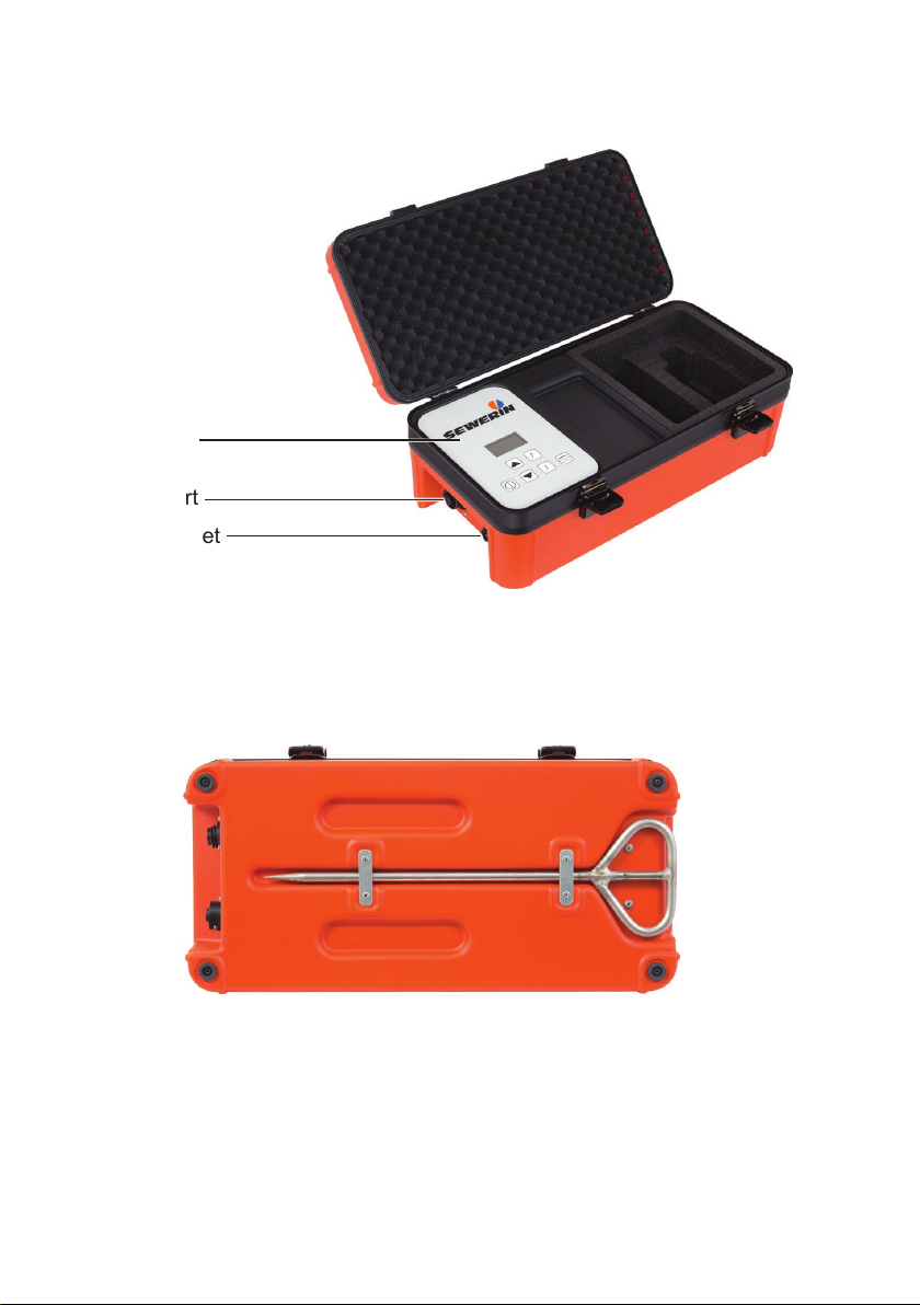
Fig. 1: FG 150 generator with opened case
Control panel
Charging socket
Cable set port
Fig. 2: Case with earthing spike (view from below)

FG 150 generator
Fig. 4: Display with main view
kHz
mA
Frequency
Signal strength
Current
Fig. 3: Control panel
Signal behaviour
(here: continuous signal)
Display
ON/OFF key
Frequency keys
Pulse button
State of charge
Arrow keys
●Up key
●Down key

Illustration of warnings in this document
AWARNING!
Risk of personal injury. Could result in serious injury or death.
ACAUTION!
Risk of personal injury. Could result in injury or pose a risk
to health.
NOTICE!
Risk of damage to property.

Contents│ I
1 Introduction .............................................................................1
1.1 Information about this document...............................................1
1.2 Purpose.....................................................................................1
1.3 Intended use .............................................................................1
1.4 Safety information .....................................................................2
2 Product description ................................................................3
2.1 General .....................................................................................3
2.2 Ports..........................................................................................3
2.3 Settings and adjustments..........................................................3
2.3.1 Frequencies ...........................................................................4
2.3.2 Signal strength .......................................................................5
2.3.3 Signal behaviour ....................................................................7
2.4 Power supply.............................................................................7
3 Energizing a pipeline ..............................................................8
3.1 Switchingthegeneratoronando............................................8
3.2 Setting the frequency ................................................................9
3.2.1 Selecting the frequency..........................................................9
3.2.2 Activating and deactivating frequencies.................................9
3.2.3 Adding a frequency ..............................................................10
3.3 Adjusting the signal strength ................................................... 11
3.4 Selecting the signal behaviour ................................................12
3.5 Energizing a pipeline directly ..................................................12
3.5.1 Connection via conductor loop.............................................12
3.5.2 Connection with earthing spike ............................................13
3.6 Energizing a pipeline indirectly................................................14
4 Maintenance ..........................................................................16
4.1 Recharging the battery............................................................16
4.2 Care ........................................................................................17
4.3 Maintenance............................................................................17
4.4 Troubleshooting.......................................................................18
5 Appendix................................................................................19
5.1 Technical data .........................................................................19
5.2 Preset frequencies ..................................................................20
5.3 Symbols on the display ...........................................................21
5.4 Accessories.............................................................................21


1 Introduction│ 1
1 Introduction
1.1 Information about this document
This document is a component part of the product.
●Read the document before putting the product into operation.
●Keep the document within easy reach.
●Pass this document on to any subsequent owners.
● Unlessotherwisespecied,theinformationinthisdocument
refers to the product as delivered (factory settings) and applies
to all product variants.
Translations
Translations are produced to the best of our knowledge. The
original German version is authoritative.
Right of reproduction
Nopartofthisdocumentmaybeedited,duplicatedorcirculated
in any form without the express consent of Hermann Sewerin
GmbH.
Registered trademarks
Registered trademarks are generally not indicated in this docu-
ment.
1.2 Purpose
The portable FG 150 generator is part of the FERROPHON sys-
tem. The generator is suitable for energizing pipelines laid out-
doors.
1.3 Intended use
The product is suitable for the following uses:
●Professional
●Industrial
●Commercial

2 │1Introduction
Theproductmustonlybeusedfortheapplicationsspeciedin
section 1.2.
The product may only be used by the following persons1:
●Technicians
●Trained persons
1.4 Safety information
This product was manufactured in keeping with all binding legal
and safety regulations.
The product is safe to operate when used in accordance with the
instructionsprovided.However,whenhandlingtheproduct,there
mayberiskstopersonsandproperty.Forthisreason,observe
the following safety information without fail.
●Observe all the applicable safety standards and accident pre-
vention regulations.
●Use the product only as intended.
● Donotmakeanychangesormodicationstotheproductun-
less these have been expressly approved by Hermann Sew-
erin GmbH.
●Only use accessories approved by Hermann Sewerin GmbH.
●Always observe the permitted operating and storage temper-
atures.
● Handletheproductcarefullyandsafely,bothduringtransport
and when working. For example:
−Do not drop the generator.
−Always set the generator down carefully.
−Secure the generator against slipping when transporting it
in the vehicle.
● Alwaysadequatelycordonotheworkarea.
●Do not use the product if it is damaged or faulty.
● Protecttheportsandsocketsagainstdirt,andelectricalports
in particular against moisture.
●Proceed with extreme caution in the vicinity of electrical lines.
1asdenedinEN62368-1

2 Product description│ 3
2 Product description
2.1 General
The FG 150 generator can energize electroconductive pipelines
directly or indirectly. A continuous or pulsed alternating current is
transmitted. The frequency and signal strength of the generator
can be adapted to local conditions.
Tolocateapipelineenergizedbythegenerator,areceiverisre-
quired whose reception frequency can be brought into line with
the generator's transmission frequency.
The generator is permanently installed in a case. Overviews with
the names of the generator parts can be found in the front cover
(g.1tog.3).
The scope of delivery of the generator includes:
●FG 150 cable set
●Extension for cable set
●Earthing spike
Assoonasthecablesetisconnectedtothegenerator,thegen-
eratorcanenergizedirectly.Withoutthecablesetconnected,the
generator energizes indirectly.
2.2 Ports
The generator has the following ports:
●Charging socket
for connecting AC/DC adapter L or vehicle cable L
●Cable set port for connecting cable set FG 150
2.3 Settings and adjustments
Whenswitchedon,temporaryadjustmentscanbemadetothe
generator and certain settings can be saved permanently.

4 │2Productdescription
Toenergizeapipeline,adjustmentsmustbemadetoallowfor
the particular local requirements:
●Frequency
●Signal strength
●Signal behaviour
Whenswitchingo,thefrequency1is saved; signal strength and
signal behaviour are not saved.
The following settings are saved permanently:
●Activation state of the frequencies (deactivated/activated)
●Individually added frequencies
2.3.1 Frequencies
Various preset frequencies are available for energizing (sec-
tion 5.2).Fordirectenergizing,individualfrequenciescanbeset
up in addition to the preset ones.
Frequenciescanbedeactivated.Deactivatingcanbeusefulif,of
allthepresetandindividualfrequencies,onlycertainfrequencies
areneededfordailywork.Inthemainview(g.4)thenumber
of selectable frequencies becomes smaller by deactivation. A
desired frequency can thus be selected more quickly.
Thelistoffrequencies(g.1)isalwaysstructuredasfollows:
1. Position 1 - 10
Frequency list 1 and Frequency list 2 views
●Factory-set frequencies for direct and indirect energizing
2. Position 11 - 15
Frequency list 3 view
●Individual frequencies for direct energizing
Aslongasnoindividualfrequenciesaresetup,positions
11 - 15 are assigned the lowest possible frequency (200 Hz).
1The generator stores the last used frequency for both direct energizing
and indirect energizing.

2 Product description│ 5
F1requency list
x 512 Hz <
x 640 Hz
x 1100 Hz
x 8192 Hz
X 9950 Hz
Frequency list 3
o 200 Hz <
o 200 Hz
o 200 Hz
o 200 Hz
o 200 Hz
Fig. 5: Frequency list view - List of frequencies
x Frequencyactivated,deactivationpossible
X Frequencyactivated,deactivationnotpossible
o Frequencydeactivated,activationpossible
Left image: Frequency list 1 with 5 preset frequencies
Right image: Frequency list 3 with placeholders for 5 individual
frequencies
The list of frequencies is protected against accidental change
by PIN code.
PIN-Code
Fig. 6: PIN-Code view
2.3.2 Signal strength
The signal strength corresponds to the output power of the gen-
erator. The maximum output power depends on the signal be-
haviour:
●Continuous signal: max. 25 W
●Pulsed signal: max. 50 W
Whether these values are actually achieved depends on local
conditions.
The signal strength can be changed in steps.

6 │2Productdescription
Current in energized pipelines
Inenergizedpipelines,thecurrentislimitedbythegenerator:
●Continuous signal: max. 0.5 A
●Pulsed signal: max. 1 A
Ifthesevaluesarealreadyreachedatmediumsignalstrength,
the generator does not increase the actual signal strength any
further. This also applies if the Up key is pressed further and an
increased signal strength is then displayed.
Safe-to-touch range
As long as the signal strength does not show more than 3 bars
(g.3,leftpicture),the generatoroperatesinthe touch-safe
range ES12. When the Noticesymbolappears(g.3,pictureon
the right) the generator operates in the ES2 range3.
NOTICE!
IntheES2range,contactbetweenmetalparts(e.g.clamps,
earthing spike) and a body part is painful but is not expected to
causeinjury.Nevertheless,theuserisresponsibleforensuring
that persons or animals do not accidentally touch the metal parts.
●Secure the work area especially carefully when working in the
ES2 range.
TogetfromrangeES2backtorangeES1,thesignalstrength
must be reduced (section 3.3).
2ES1: Electrical energy source class 1. Information on this in EN 62368-1
(4.2).
3anlogue ES1

2 Product description│ 7
kHz
mA
kHz
mA
Fig. 7: Main view
Left image: Signal strength in ES1 range (safe-to-touch range)
Right image: Signal strength in ES2 range (Notice symbol)
2.3.3 Signal behaviour
The generator can optionally be operated with the following sig-
nal behaviour:
●Continuous signal
●Pulsed signal
withpulsedsignal,thesignalcycleis1:2(pulse:pause).
Note:
Operation with pulsed signal extends the operating time of the
generator compared to operation with continuous signal.
The signal behaviour determines the maximum output power of
the generator as well as the maximum current in the energized
pipeline (section 2.3.2).
2.4 Power supply
Thegeneratorispoweredbyaspecial,permanentlyinstalledPb
battery. Information about charging the rechargeable battery can
be found in section 4.1.

8 │3Energizingapipeline
3 Energizing a pipeline
AWARNING!
Danger of electrical shock!
High voltages may be present at exposed parts of pipe-
lines.
●
Always observe the current rules when working near
live pipelines.
●
Donottouchanyliveparts(e.g.terminals,ttings,
earthing spike) during direct energizing.
● Alwaysadheretothespeciedsequenceofsteps.
NOTICE!
Whenthelidisopen,moisturecangetintothecase.Permanent
moisture can cause damage to the generator and the case insert.
●
Whenwet,openthegeneratorcaseonlyaslongasnecessary
for operation.
3.1 Switching the generator on and o
Switching on
● PresstheOn/Okeyforapprox.1second.
Astartupscreenappearsbrieyonthedisplay,indicatingthe
rmwareversion.Thenthemainviewappears(g.4).
Switching o
● PresstheOn/Okeyforapprox.2seconds.
Thegeneratorswitcheso.

3 Energizing a pipeline│ 9
3.2 Setting the frequency
3.2.1 Selecting the frequency
The frequency for energizing must always be adapted to the
local conditions.
Note:
The generator and receiver must operate at the same frequency.
●
Adjust the frequency of the receiver to the frequency of the
generator.
The generator is switched on. The display shows the main
view.
●Press one of the frequency keys repeatedly until the desired
frequency is displayed.
3.2.2 Activating and deactivating frequencies
The factory setting is that all preset frequencies are activated.
Activated frequencies can be selected in the main view using
frequency keys.
Note:
The frequencies for indirect energizing cannot be deactivated.
Thegeneratorisswitchedo.
1. Open the PIN-Codeview(g.6).
● SimultaneouslypressbothfrequencykeysandtheOn/O
key until the PIN-Code view appears.
2. Enter the PIN code 0001.
●Press the arrow keys to move the cursor right or left.
●
Press the frequency keys to increase or decrease the digits.
● PresstheOn/OkeytocompletethePINcodeentry.
The Frequency list 1view(g.5,leftimage)appears.

10 │3Energizingapipeline
3. Deactivate or activate the desired frequencies.
a) Press the arrow keys to select a frequency.
b) Press the pulse key to deactivate or activate the selected
frequency.
xFrequency activated
oFrequency deactivated
c) PresstheOn/Okeytoapplythesetting.
4. Press the Down key repeatedly until the main view appears
again.
3.2.3 Adding a frequency
Fordirectenergizing,upto5additionalfrequenciescanbeadd-
ed to the factory-set frequencies. If individual frequencies have
alreadybeencreated,thesecanalsobeoverwritten.
Frequency list 3
o 135 Hz < Edit9
o 200 Hz
o 200 Hz
o 200 Hz
o 200 Hz
Fig. 8: Frequency list 3 view - Individual frequencies (here: top place-
holder occupied by individual frequency 1359 Hz)
Thegeneratorisswitchedo.
1. Open the PIN-Codeview(g.6).
● SimultaneouslypressbothfrequencykeysandtheOn/O
key until the PIN-Code view appears.
2. Enter the PIN code 0001.
●Press the arrow keys to move the cursor right or left.
●
Press the frequency keys to increase or decrease the digits.
● PresstheOn/OkeytocompletethePINcodeentry.
●The Frequency list 1view(g.5,leftimage)appears.

3 Energizing a pipeline│ 11
3. Press the Down key until the Frequency list 3 view appears
(g.5,rightimage).
4. Use the arrow keys to select a placeholder to be overwritten
with an individual frequency.
5. Press the ON/OFF key. The placeholder is marked with Edit
(g.4).
6. Set the desired frequency.
The frequency can be between 200 Hz - 116.000 kHz.
●Press the arrow keys to move the cursor right or left.
●
Press the frequency keys to increase or decrease the digits.
● PresstheOn/Okeytonishenteringthefrequency.The
Edit marking disappears.
7. Press the pulse key to activate the new frequency.
8. Press the Down key repeatedly until the main view appears
again.
3.3 Adjusting the signal strength
The signal strength can be changed in steps.
The generator is switched on. The display shows the main
view.
●Press the Up key to increase the signal strength.
●Press the Down key to reduce the signal strength.
The signal strength changes with each keystroke.
Notes:
Even if in the Signal strengthdisplaynosegmentislled,the
generator still supplies power.
Observe the notes on working in the touch-safe range in sec-
tion 2.3.2.
12 │3Energizingapipeline
3.4 Selecting the signal behaviour
On the generator it is possible to select between continuous sig-
nal and pulsed signal.
The generator is switched on. The display shows the main
view.
●Press the pulse key to switch between continuous signal and
pulsed signal.
The symbol of the selected signal behaviour is displayed.
3.5 Energizing a pipeline directly
Duringdirectenergizing,thegeneratorsendsasignalbymeans
of cable to the pipeline to be located. The prerequisite is that
a connection can be made at at least one exposed part of the
pipeline.
The following options are available for direct energizing:
●Connection via conductor loop
●Connection with earthing spike
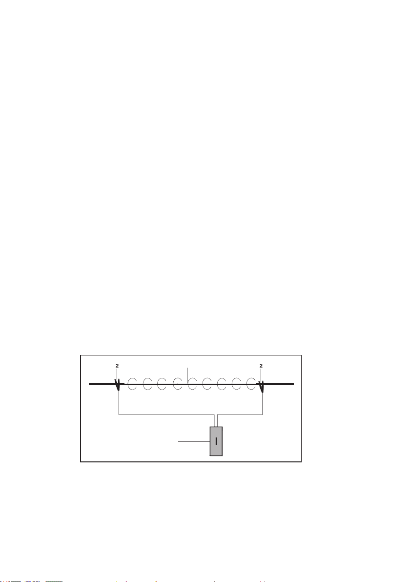
3.5.1 Connection via conductor loop
Forconnectionviaaconductorloop,twoconnectionpointsare
required on the pipeline. The pipeline to be located must run be-
tween the two connection points.
3
1
Fig. 9: Energizing via conductor loop
1 Energized section of pipeline
2 Terminals of the cable set
3 Generator

3 Energizing a pipeline│ 13
1. Makesurethatthegeneratorisswitchedo.
2. Connect the cable set to the generator.
3.
Attach a clamp of the cable set to an exposed part of the
pipeline to be energized.
4. Attach the second clamp of the cable set to the second con-
nection point.
●
Select the second exposed connection point so that the
pipeline to be located is within the two connection points.
5. Switch on the generator.
6. Select the frequency.
7. Adjust the signal strength.
8. Choose between continuous signal or pulsed signal.
The pipeline is energized with the selected settings.
Ending direct energizing
1. Switchothegenerator.
2. Disconnect the cable set from the generator.
3. Disconnect the terminals from the pipeline.
3.5.2 Connection with earthing spike
Ifthereisonlyoneconnectionoptiononapipeline,anearthing
spike can be used.
ACAUTION! Risk of injury from tip
The earthing spike has a tip.
●
Always be especially careful when working with the
earthingspike,especiallyinthevicinityofotherper-
sons.
●Avoid dropping the earthing spike.
The earthing spike is placed in the ground. SEWERIN recom-
mends: The distance from the earthing spike to the pipeline
should be at least 3 m.

14 │3Energizingapipeline
P
P
Fig. 10: Energizing with earthing spike
1 Electrical connection to the pipeline to be located
2 Generator
3 Earthing spike
1. Makesurethatthegeneratorisswitchedo.
2. Connect the cable set to the generator.
3. Inserttheearthingspikermlyintotheground.
4. Attach a clamp to the earthing spike.
5. Attach the second clamp of the cable set to the exposed part
of the pipeline to be energized.
6. Switch on the generator.
7. Select the frequency.
8. Adjust the signal strength.
9. Choose between continuous signal or pulsed signal.
The pipeline is energized with the selected settings.
Ending direct energizing
1. Switchothegenerator.
2. Disconnect the cable set from the generator.
3. Disconnect the clamps from the pipeline and from the earth-
ing spike.
3.6 Energizing a pipeline indirectly
Ifnodirectconnectiontoapipelineispossible,thegenerator
can be used to indirectly energize a pipeline without a cable con-
nection.Foroptimumindirectenergizing,thegeneratormustbe
positioned as accurately as possible lengthways over the pipe-
line(g.7).
Table of contents
Other sewerin Portable Generator manuals


Popular Portable Generator manuals by other brands

Generac Power Systems
Generac Power Systems 7500 owner's manual

Firman
Firman P03504 Operator's manual

Jackery
Jackery Explorer 1000 Pro user manual

Generac Power Systems
Generac Power Systems 005802-2 XG Professional Series owner's manual

Coleman
Coleman Powermate PM0495503.01 manual

Atlas Copco
Atlas Copco QAC 1100 Sd instruction manual


Sears
Sears CRAFTSMAN 919.679500 owner's manual

Buffalo
Buffalo Sportsman GEN7000 instruction manual

Himoinsa
Himoinsa HM130A1 Series Operating and maintenance instructions

Mech Marvels
Mech Marvels MM2000I instruction manual

Harbor Freight Tools
Harbor Freight Tools PREDATOR 59134 user manual

SioGreen
SioGreen IR-3000 Operational Instruction Manual