sewerin FERROPHON FG 50 User manual

02.09.2019 a – 107631 – en
FERROPHON®
FG 50 generator
Operating Instructions

FG 50 generator
Arrow keys
●Up key
●Down key
ON/OFF key
Frequency keys
Fig. 1: FG 50 generator viewed from various angles
Cable set connection
Charging socket
Display

FG 50 generator
kHz
mA
Frequency
Output power
Current
Fig. 2: Display with main view
Charge

Illustration of warnings in this document
AWARNING!
Risk of personal injury. Could result in serious injury or death.
NOTICE!
Risk of damage to property.

Contents│ I
1 Introduction .............................................................................1
1.1 Information about this document...............................................1
1.2 Purpose.....................................................................................1
1.3 Intended use .............................................................................2
1.4 Safety information .....................................................................2
2 Product description ................................................................3
2.1 Operating principle ....................................................................3
2.2 Ports..........................................................................................3
2.3 Power supply.............................................................................3
2.3.1 Powered by rechargeable battery ..........................................3
2.3.2 External power supply............................................................4
3 Using the generator ................................................................5
3.1 Switchingthegeneratoronando............................................5
3.2 Energize line .............................................................................5
3.2.1 General information for locating by energizing.......................5
3.2.2 Connection via conductor loop...............................................5
3.2.3 Connection with earthing spike ..............................................6
3.2.4 Set frequency .........................................................................8
3.2.5 Setting the output power ........................................................8
3.2.6 Stop energizing ......................................................................9
4 Maintenance ..........................................................................10
4.1 Charging the batteries.............................................................10
4.1.1 Charging the battery in the case ..........................................10
4.1.2 Charging batteries individually using the AC/DC adapter
or vehicle cable .................................................................... 11
4.2 Handling faulty lithium ion rechargeable batteries ..................12
4.2.1 Identifying faulty batteries ....................................................12
4.2.2 Removing the battery ...........................................................13
4.3 Care ........................................................................................13
4.4 Servicing .................................................................................14
4.5 Dealing with problems.............................................................14
5 Appendix................................................................................15
5.1 Technical data .........................................................................15
5.2 Accessories.............................................................................16
5.3 Declaration of conformity ........................................................16
5.4 Advice on disposal ..................................................................17
6 Index.......................................................................................18

1 Introduction│ 1
1 Introduction
1.1 Information about this document
This document is a component part of the product.
●Read the document before putting the product into operation.
●Keep the document within easy reach.
●Pass this document on to any subsequent owners.
● Unlessotherwisespecied,theinformationinthisdocument
refers to the product as delivered (factory settings) and applies
to all product variants.
Translations
Translations are produced to the best of our knowledge. The
original German version is authoritative.
Right of reproduction
Nopartofthisdocumentmaybeedited,duplicatedorcirculated
in any form without the express consent of Hermann Sewerin
GmbH.
Registered trademarks
Registered trademarks are generally not indicated in this docu-
ment.
1.2 Purpose
The portable FG 50 generator is part of the FERROPHON sys-
tem.
The generator is used to energize lines when locating pipes. It
can be used with selected receivers of the AQUAPHONsystem,
e.g. AF 50 receiver.
Note:
These operating instructions describe the functions of the FG 50
generatorwithrmware version 1.xxx.The manufacturer re-
serves the right to make changes.

2 │1Introduction
1.3 Intended use
The product is suitable for the following uses:
●professional
●industrial
●commercial
The product mustonlybeusedfortheapplicationsspeciedin
section 1.2.
Note:
The appropriate specialist knowledge is required for using this
product.
1.4 Safety information
This product was manufactured in keeping with all binding legal
and safety regulations.
The product is safe to operate when used in accordance with the
instructionsprovided.However,whenhandlingtheproduct,there
mayberiskstopersonsandproperty.Forthisreason,observe
the following safety information without fail.
●Observe all the applicable safety standards and accident pre-
vention regulations.
●Use the product only as intended.
●Donotmakeanychangesormodicationstotheproductun-
less these have been expressly approved by Hermann Sewerin
GmbH.
●
Only use accessories and consumables approved by Hermann
Sewerin GmbH.
●Always observe the permitted operating and storage temper-
atures.
● Handletheproductcarefullyandsafely,bothduringtransport
and when working.
● Alwaysadequatelycordonotheworkarea.
●Do not use the product if it is damaged or faulty.
● Protecttheportsandsocketsagainstdirt,andelectricalports
in particular against moisture.

2 Product description│ 3
2 Product description
2.1 Operating principle
The FG 50 generator can be used to directly energize electrically
conductive lines. The generator is designed for use in buildings.
An alternating current is sent.
Transmitting frequency and output power are selected depending
on the local conditions.
The frequency and power can be set on the generator.
2.2 Ports
The generator has the following ports:
●Charging socket For charging the rechargeable battery.
The following can be connected:
– M4 AC/DC adapter
– M4 vehicle cable
– Connection cable in case SK 10
●Cable set connection For connecting the universal cable
set.
2.3 Power supply
The generator can be operated:
●with rechargeable battery
●externally via AC/DC adapter/vehicle cable
2.3.1 Powered by rechargeable battery
The FG 50generatorisequippedwithaspecial,built-inlithium
ion rechargeable battery.
The battery must be charged regularly. Information about charg-
ing the rechargeable battery can be found in section 4.1.
NOTICE! Reduced battery life when not in use
The battery in the receiver can discharge (self-discharge) even
when the receiver is not in use.
●You should charge the battery at least once every 6 months.

4 │2Productdescription
NOTICE! Risk of damage when changing the lithium ion
battery
There are parts in the receiver that can be damaged mechan-
ically or by electrostatic discharge when changing the battery.
●
Only SEWERIN service personnel or other authorised special-
ists may replace the lithium ion rechargeable battery.
AWARNING! Risk of explosion due to short-circuit
Faulty lithium ion rechargeable batteries can explode due
to internal short-circuit.
●
Components containing faulty lithium ion batteries must
not be shipped.
2.3.2 External power supply
Thegeneratorcanalsobepoweredexternally(12V).Todothis,
the generator is connected to a suitable power source using the
AC/DC adapter or vehicle cable.
Withanexternalpowersupply,themaximumtransmittingpower
is reduced.

3 Using the generator│ 5
3 Using the generator
3.1 Switching the generator on and o
Switching on
●Press the ON/OFF key for approx. 1 second.
A start screen with the rmwareversionwillappearbrieyon
the display. The main view then appears.
Switching o
●Press the ON/OFF key for approx. 2 seconds.
Thegeneratorswitcheso.
3.2 Energize line
3.2.1 General information for locating by energizing
Inordertobeabletolocatealine,itmustcarryacurrentwitha
certainfrequency,sothatanelectromagneticeldisgenerated.
Thiseldisthenlocated.
Lines that are not carrying a current must be energized for lo-
cating.
Direct energizing involves supplying power from a generator to
the line via a cable. This is only possible if a galvanic connection
can be made to at least an exposed part of the line.
The following options are available for direct galvanic connection:
●Connection via conductor loop
●Connection with earthing spike
3.2.2 Connection via conductor loop
Two connection options on the line are required for direct galvan-
ic connection via a conductor loop. The line to be located must
be located between the two connection points.

6 │3Usingthegenerator
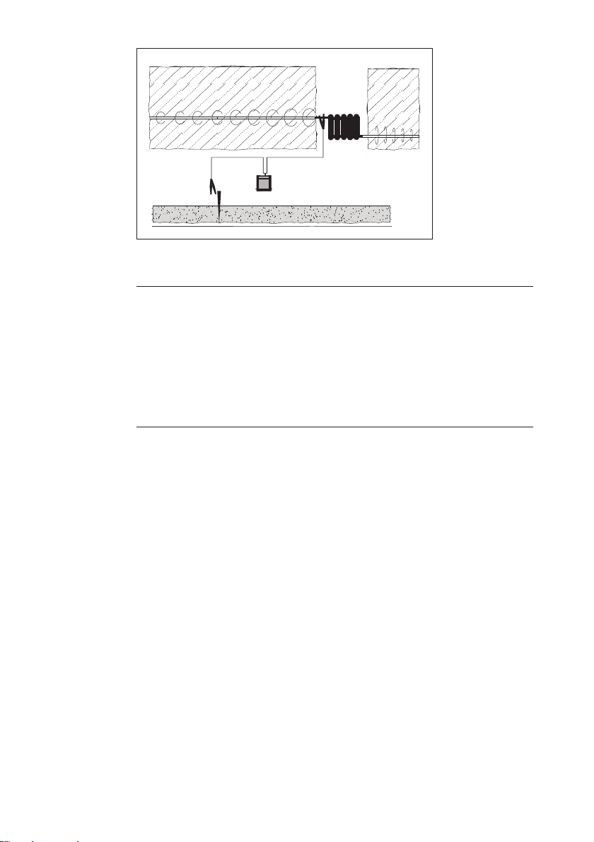
Fig. 3: Direct galvanic connection via conductor loop
AWARNING! Risk of injury from electric shock
High voltages can be applied to exposed parts of the lines.
●Disconnect electrical lines before locating.
● Observethespeciedsequenceofactions.
Thegeneratorisswitchedo.
1. Attach one terminal of the cable set to an exposed part of the
line to be energized.
2.
Attach the second terminal of the cable set to another ex-
posed part of the line to be energized.
3. Connect the cable set to the generator.
4. Switch on the generator.
5. Set the frequency (section 3.2.4).
6. Set the output power (section 3.2.5).
The line is energized with the selected settings.
3.2.3 Connection with earthing spike
The direct galvanic connection with earthing spike can be used
if there is only one connection option on the line.
The earthing spike is placed outside of buildings in the ground.
The distance from the earthing spike to the line must be at least
3 metres. The electrical conductivity of the ground is improved
by moisture. SEWERIN recommends: Moisten the ground if nec-
essary.
3 Using the generator│ 7
P
P
Fig. 4: Direct galvanic connection with earthing spike
AWARNING! Risk of injury from electric shock
High voltages can be applied to exposed parts of the lines.
●
Never connect the terminals of the cable set to lines
that are already live.
● Observethespeciedsequenceofactions.
●
Always switch o the generator before moving the
earthing spike.
Thegeneratorisswitchedo.
1. Attach one terminal of the cable set to an exposed part of the
line to be energized.
2.
Inserttheearthingspikermlyintothegroundoutsideabuild-
ing.
−Maintain a minimum distance of 3 meters from the line to
be located.
3. Attach the second terminal to the earthing spike.
4. Connect the cable set to the generator.
5. Switch on the generator.
6. Set the frequency (section 3.2.4).
7. Set the output power (section 3.2.5).
The line is energized with the selected settings.
8 │3Usingthegenerator
3.2.4 Set frequency
Thegeneratorcantransmitwithdierentfrequencies.Theop-
tions are:
−512 Hz
−1.1 kHz
−9.95 kHz
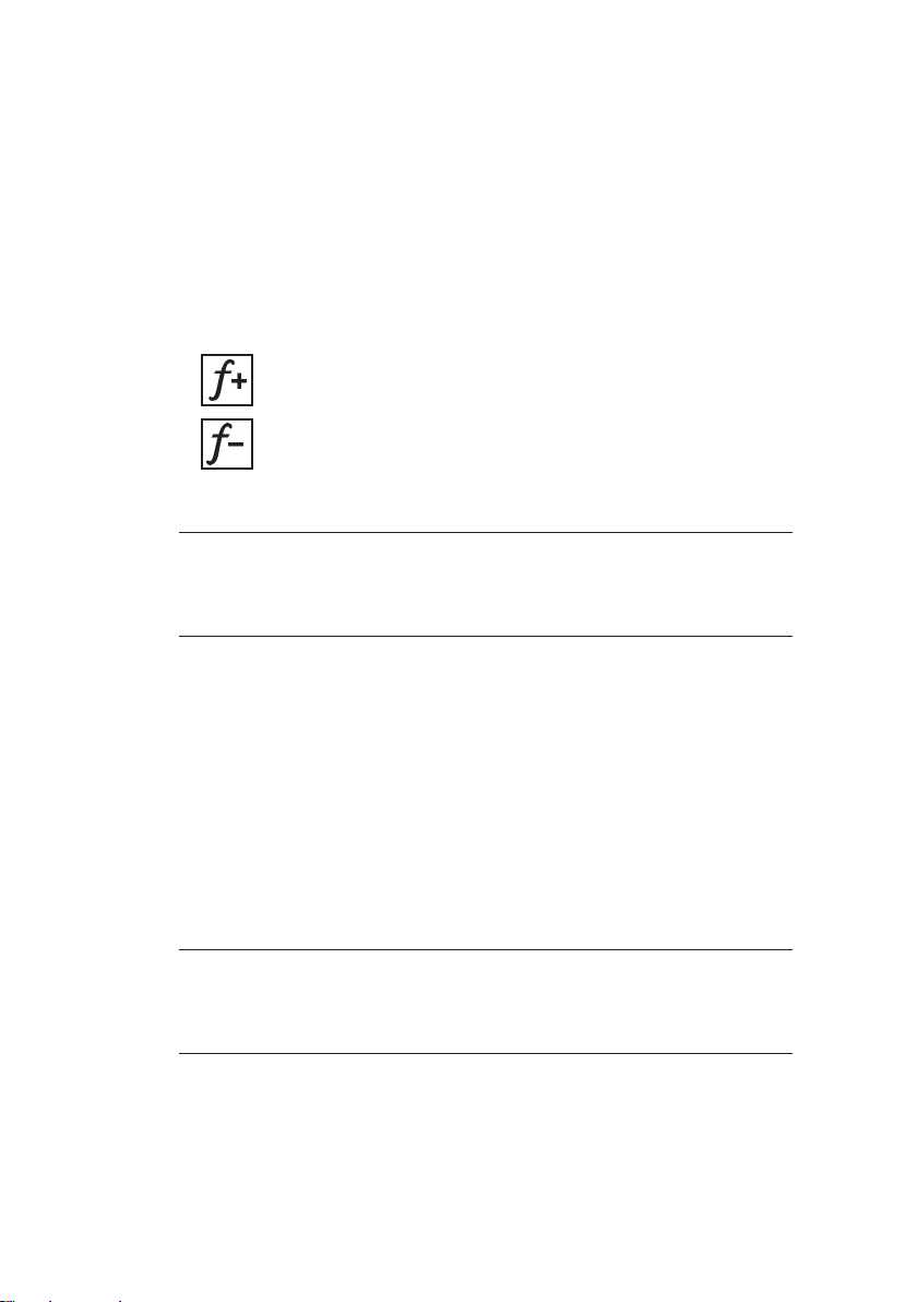
●Press one of the two frequency keys to set the frequency.
Increase frequency
Reduce frequency
Note:
The generator and receiver must be of the same frequency.
●Adjust the receiver frequency to the generator frequency.
3.2.5 Setting the output power
The output power of the FG 50 generator can be adjusted to the
conditions.
Assoonasthegeneratorisswitchedon,itwillsupplyanoutput
power of up to 1 Watt in battery operation. Whether the generator
can actually deliver this value depends on the local conditions.
The output power can be changed gradually.
Note:
Evenifnosegmentislledintheoutput powersymbol,the
generator still delivers power.
Intheenergizedline,thecurrentfromthegeneratorislimited
to 100 milliamps. If this value is already reached at average
outputpower,thegeneratorwillnotincreasetheactualoutput

3 Using the generator│ 9
power any further. This also applies if the Up key continues to
be pressed and the output power symbol then displays an in-
creased output power.
●Press the Up key to increase the output power.
●Press the Down key to reduce the output power.
3.2.6 Stop energizing
Oncethelocatingprocesshasbeencompleted,thefollowing
steps must be carried out in the following order:
1. Switchothegenerator.
2. Disconnect the cable set from the generator.
3. Disconnecttheterminalsfromthelineand,ifnecessary,from
the earthing spike.

10 │4Maintenance
4 Maintenance
4.1 Charging the batteries
The rechargeable battery of the FG 50 generator must be
charged,if necessary.The typicalchargingtimeislessthan
6 hours.
The battery is protected against overcharging. Therefore the gen-
erator can be left connected to the power supply once it is fully
charged.
Always observe the permitted temperature range during charg-
ing.Ifthetemperaturefallsbeloworexceedsthelimitvalues,
charging stops until the temperature returns to within the per-
mitted range.
There are two ways to charge the FG 50 generator:
●simultaneously with the AQUAPHON system components in
the SK 10 case
●individually by AC/DC adapter or vehicle cable
4.1.1 Charging the battery in the case
The rechargeable battery of the FG 50 generator can be charged
simultaneously with the AQUAPHON system components in the
SK 10 case. The case is connected to the power supply using
the LAC/DC adapter or the Lvehicle cable.
The LAC/DC adapter and the Lvehicle cable are available to
buy as accessories.
The connection cable for the components can be found in the
case. There is a connection socket on the outside of the case for
connecting to the power supply.

4 Maintenance│ 11
Fig. 5: SK 10 case
White circles: Connection cable
Black arrow: Connection socket (on the outside)
1. Place the components in the dedicated spaces in the case.
2. Connect the components using the connection cables.
3.
Connect the case to the power supply using the LAC/DC
adapter or the Lvehicle cable. Charging starts automatically.
The charging process is complete after less than 6 hours.
4.1.2 Charging batteries individually using the AC/DC adapter or
vehicle cable
The FG 50 generator is connected directly to the power supply for
charging using the M4 AC/DC adapter or the M4 vehicle cable.
The generator is charged individually.
The M4 AC/DC adapter and the Lvehicle cable are available to
buy as accessories.

12 │4Maintenance
4.2 Handling faulty lithium ion rechargeable batteries
Lithium ion batteries are always classed as dangerous goods for
transport purposes.
The transportation of faulty lithium ion batteries is only permit-
ted under certain conditions (e.g. must not be transported as air
freight).Wheretransportationispermitted(e.g.byroadorrail),
it is subject to strict regulations. Faulty lithium ion batteries must
therefore always be removed before shipping. Transportation by
road or rail must occur in compliance with the current applicable
version of the ADR1regulations.
NOTICE! Risk of damage when opening housing
Whenopeningthehousing,componentscanbedamagedme-
chanically or by electrostatic discharge.
●The lithium on battery may only be removed if you have legit-
imate grounds to suspect that the battery may be defective.
●Only SEWERIN Service personnel or an authorized specialist
may replace rechargeable batteries.
4.2.1 Identifying faulty batteries
A lithium ion battery is considered to be faulty if one of the fol-
lowing criteria applies:2
●Housing damaged or badly deformed
●Liquid leaking from battery
●Smell of gas from battery
● Riseintemperaturewiththereceiverswitchedo(morethan
hand-hot)
●Plastic parts melted or deformed
●Connection leads melted
1French abbreviation for: Accord européen relatif au transport internation-
aldesmarchandisesDangereusesparRoute,*Engl.:EuropeanAgree-
ment concerning the International Carriage of Dangerous Goods by
Road
2According to: EPTA – European Power Tool Association

4 Maintenance│ 13
4.2.2 Removing the battery
The rechargeable battery is located in the generator. The upper
part and the lower part of the housing are screwed together.
NOTICE! Risk of damage
There are parts in the generator that may be damaged mechan-
ically or by electrostatic discharge when removing the battery.
●It is essential to read section 4.2 and section 4.2.1 before re-
moving the battery.
●
Avoidelectrostaticdischargesatallcosts,e.g.byusingan
ESD workstation.
Switchothegenerator.
1. Undo the four screws on the bottom section of the housing.
2. Carefullyliftothebottomsectionofthehousing.
3.
Disconnect the electrical supply to the faulty battery. Carefully
remove the white plug on the circuit board.
4. Thebatteryisxedinplaceinthebottomsectionofthehous-
ing by means of a retaining plate. Loosen the three screws
on the retaining plate.
5. Remove the battery.
6. Screw down the retaining plate again.
7.
Screw the bottom section of the housing to the top section
again.
4.3 Care
All that is necessary to care for the generator is to wipe it down
with a damp cloth.
14 │4Maintenance
NOTICE! Risk of damage
The display surface of the FG 50 generator is sensitive to me-
chanical and chemical stress.
● Alwaysuseaclean,softclothtocleanthedisplaysurface.
●
Never use cleaning agents containing aggressive constituents
(e.g. acidic or abrasive constituents) to clean the display sur-
face.
SEWERINrecommends:Alwaysremovesignicantcontamina-
tion immediately.
4.4 Servicing
SEWERIN recommends: Have the FG 50 generator serviced
regularly by SEWERIN Service or an authorized professional.
Only regular maintenance can ensure that the generator is al-
ways ready for use.
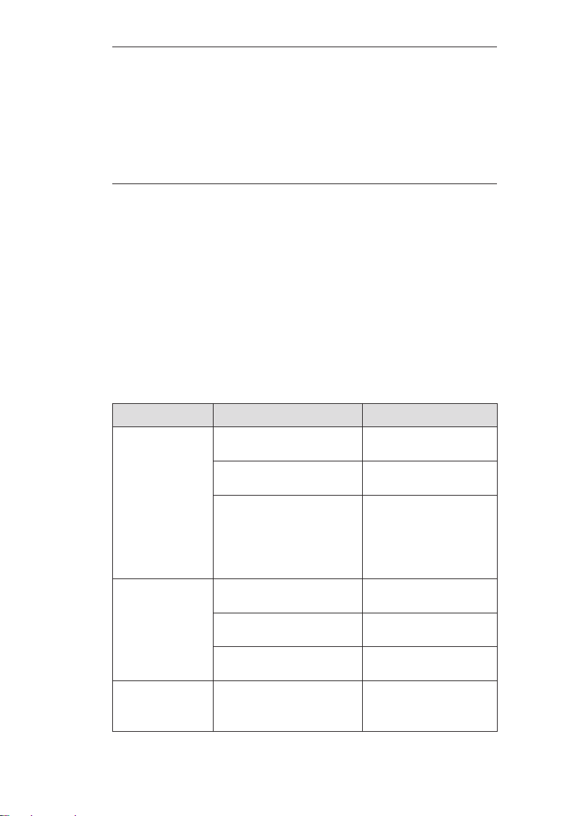
4.5 Dealing with problems
Problem Possible cause Corrective action
FG 50 cannot
be switched on
Insucientpowersup-
ply
●Recharge battery
ON/OFF key not
pressed long enough
●Press ON/OFF key
for at least 1 s
Rechargeable battery
hasswitcheditselfo
(e. g. due to short cir-
cuit when inserted)
●Charge battery
briey:connect
charger and re-
move again imme-
diately.
Energizing not
working
Line is not electrocon-
ductive
—
Set of cables faulty ●Replace faulty set
of cables
Cable set not correctly
connected
●Check connections
FG 50 switches
oduringener-
gizing
Insucientpowersup-
ply
●Reduce power at
FG 50
●Recharge battery

5 Appendix│ 15
5 Appendix
5.1 Technical data
Device data
Dimensions (W x D x H) 115 x 114 x 60 mm
Weight 410 g
Material polycarbonate (housing)
Certicate
Certicate FCC,CE
Features
Display 2"FSTNdisplay(240x128pixels,LED
backlight)
Processor DSP 16 bit
Operation membrane keypad
Operating conditions
Operating temperature -20 – 50 °C
Transmitting power -20 – 50 °C
Humidity 15% – 90% non-condensing
Protection rating IP 65
Non-permitted operating
environments
in potentially explosive areas
Power supply
Power supply lithium ion battery (rechargeable)
[1357-0002],built-in
Operatingtime,minimum 6 h
Operatingtime,maximum 40 h
Battery power 24 Wh
Charging time < 6 h
Charging temperature 0 – 40 °C
Charging voltage 12 V
Charging current 0.6 A
Charger M4 AC/DC adapter
Table of contents
Other sewerin Portable Generator manuals


