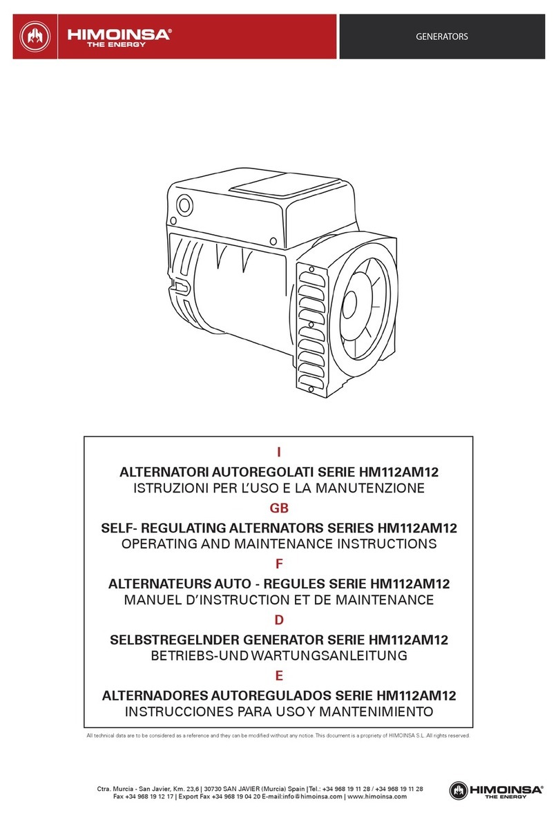
Himoinsa HM130A1 Series Manual

Ctra. Murcia - San Javier, Km. 23,6 | 30730 SAN JAVIER (Murcia) Spain |Tel.: +34 968 19 11 28 / +34 968 19 11 28
GENERATORS
PAG / 1
I
ALTERNATORI AUTOREGOLATI SERIE HM130A1
ISTRUZIONI PER L’USO E LA MANUTENZIONE
GB
SELF- REGULATING ALTERNATORS SERIES HM130A1
OPERATING AND MAINTENANCE INSTRUCTIONS
F
ALTERNATEURS AUTO - REGULES SERIE HM130A1
MANUEL D’INSTRUCTION ET DE MAINTENANCE
D
SELBSTREGELNDER GENERATOR SERIE HM130A1
BETRIEBS-UND WARTUNGSANLEITUNG
E
ALTERNADORES AUTOREGULADOS SERIE HM130A1
INSTRUCCIONES PARA USOY MANTENIMIENTO
All technical data are to be considered as a reference and they can be modified without any notice. This document is a propriety of HIMOINSA S.L..All rights reserved.
I
ALTERNATORI AUTOREGOLATI SERIE ECP3
ISTRUZIONI PER L’USO E LA MANUTENZIONE
GB
SELF- REGULATING ALTERNATORS SERIES ECP3
OPERATING AND MAINTENANCE INSTRUCTIONS
F
ALTERNATEURS AUTO - REGULES SERIE ECP3
MANUEL D’INSTRUCTION ET DE MAINTENANCE
D
SELBSTREGELNDER GENERATOR SERIE ECP3
BETRIEBS-UND WARTUNGSANLEITUNG
ES
ALTERNADORES AUTOREGULADOS SERIE ECP3
INSTRUCCIONES PARA USO Y MANTENIMIENTO
ECP3

GENERATORS
Ctra. Murcia - San Javier, Km. 23,6 | 30730 SAN JAVIER (Murcia) Spain |Tel.: +34 968 19 11 28 / +34 968 19 11 28
PAG / 2
INDICE
DESCRIZIONE MACCHINA
PREMESSA
IDENTIFICAZIONE MACCHINA
VERIFICA ALLA CONSEGNA
PRESCRIZIONI DI SICUREZZA
TRASPORTO E IMMAGAZZINAMENTO AC-
COPPIAMENTO MECCANICO
ACCOPPIAMENTO ELETTRICO
AVVIAMENTO E ARRESTO
PULIZIA E LUBRIFICAZIONE
MANUTENZIONE
ANOMALIE E RIMEDI
PARTI DI RICAMBIO
TAVOLE
DIMENSIONI D’INGOMBRO
DESCRIZIONE
MACCHINA
I generatori della serie HM130A1 sono auto-
regolati, brushless a 2 e 4 poli. Hanno indutto-
re rotante provvisto di gabbia di smorzamento
(generatori a 2 poli) e indotto fisso a cave
inclinate.
Gli avvolgimenti sono a passo raccor- ciato
per ridurre il contenuto armonico. I generatori
sono costruiti in conformità alle diret-
tive 2006/42, 2006/95, 2004/108 e
relative modifiche, alle norme CEI 2-3, EN
60034-1, IEC 34-1, VDE 0530, BS4999 - 5000.
Le prove per la verifica della compatibili- ta’
elettromagnetica sono state eseguite nelle
condizioni prescritte dalle norme, con il neutro
collegato a terra. Esecu- zioni in accordo ad
altre specifiche pos- sono essere eseguite su
richiesta del cliente.
La struttura meccanica, sempre molto robusta,
consente un facile accesso ai collegamenti e
permette di eseguire le verifiche nelle diverse
parti altrettanto facilmente.
La carcassa e’ realizzata in acciaio, gli scudi in
alluminio pressofuso, l’albero in acciaio C45
con ventola calettata. Il grado di protezione
e’ IP23 (a richiesta e’ possibile realizzare un
grado di prote- zione superiore).
Gli isolamenti sono eseguiti in classe H, le im-
pregnazioni con resine epossidiche per le parti
rotanti e trattamenti sotto- vuoto per le parti
di piu’ elevata ten- sione, quali gli statori (a
richiesta tratta- menti speciali). Nel campo dei
radio disturbi, la produzione di serie soddisfa la
norma EN61000-6-3, EN61000-6-1.
All technical data are to be considered as a reference and they can be modified without any notice. This document is a propriety of HIMOINSA S.L..All rights reserved.
MACHINE
DESCRIPTION
HM130A1 2 and 4 pole alternators are bru- shless,
self regulating and incorporate a rotating inductor
with damper cage (2 pole generators) and a fixed
stator with skewed slots. The stator windings have
a shortened pitch to reduce the harmo- nic content
of the output waveform.
The alternators are made in compliance with the
2006/42, 2006/95, 2004/108 directives and their
amendments, and the CEI 2-3, EN60034-1, IEC34-
1, VDE0530, BS 4999-5000 regulations. Tests
to verify the electromagnetic com- pability have
been carried out in the foreseen conditions by the
standards with the neutral connected to the earth.
On customer’s request alternators can be manufac-
tured according to different specifications.
The robust mechanical construction gi- ves good
access to the generator output connections, and
allows the user to in- spect the various components
with ease. The casing is made of steel, the shields
of cast iron, and the shaft of C45 steel and it has a
keyed fan.
The mechanical protection level meets standard
IP23 (upon request higher le- vels of protection
can be supplied). Insulation materials meet class
H requi- rements, and all rotating components are
epossy resins impregnated, higher voltage parts,
such as the stators, are vacuum-treated (special
treatments are available on request).Radio inter-
ference suppression meets the requirements of
EN61000-6-3, EN61000-6-1 regulations.
INDEX
MACHINE DESCRIPTION
INTRODUCTION
MACHINE IDENTIFICATION
INSPECTION ON DELIVERY
SAFETY REQUIREMENTS
TRANSPORT AND STORAGE
MECHANICAL COUPLING
ELECTRICAL CONNECTIONS
STARTING AND STOPPING OPERATIONS
CLEANING AND LUBRICATION MAINTE-
NANCE
DEFECTS AND REMEDIES
SPARE PARTS
TABLES
OVERALL DIMENSIONS
PAG.
2-3
4-5
4-5
4-5
6 - 11
12 - 15
14 -21
22-23
24-25
24-29
30-31
32-39
ECP3 Manual - April 2011 revision 01
DESCRIZIONE
MACCHINA
INDICE
I generatori della serie ECP3 sono auto-
regolati, brushless a 2 e 4 poli.
Hanno induttore rotante provvisto di
gabbia di smorzamento (generatori a 2
poli) e indotto fisso a cave inclinate.
Gli avvolgimenti sono a passo raccor-
ciato per ridurre il contenuto armonico.
I generatori sono costruiti in conformità
alle direttive 2006/42, 2006/95,
2004/108 e relative modifiche, alle
norme CEI 2-3, EN 60034-1, IEC 34-1,
VDE 0530, BS4999 - 5000.
Le prove per la verifica della compatibili-
ta’ elettromagnetica sono state eseguite
nelle condizioni prescritte dalle norme,
con il neutro collegato a terra. Esecu-
zioni in accordo ad altre specifiche pos-
sono essere eseguite su richiesta del
cliente.
La struttura meccanica, sempre molto
robusta, consente un facile accesso ai
collegamenti e permette di eseguire le
verifiche nelle diverse parti altrettanto
facilmente.
La carcassa e’ realizzata in acciaio, gli
scudi in alluminio pressofuso, l’albero in
acciaio C45 con ventola calettata.
Il grado di protezione e’ IP23 (a richiesta
e’ possibile realizzare un grado di prote-
zione superiore).
Gli isolamenti sono eseguiti in classe H,
le impregnazioni con resine epossidiche
per le parti rotanti e trattamenti sotto-
vuoto per le parti di piu’ elevata ten-
sione, quali gli statori (a richiesta tratta-
menti speciali). Nel campo dei radio
disturbi, la produzione di serie soddisfa
la norma EN61000-6-3, EN61000-6-1.
DESCRIZIONE MACCHINA
PREMESSA
IDENTIFICAZIONE MACCHINA
VERIFICA ALLA CONSEGNA
PRESCRIZIONI DI SICUREZZA
TRASPORTO E IMMAGAZZINAMENTO
ACCOPPIAMENTO MECCANICO
ACCOPPIAMENTO ELETTRICO
AVVIAMENTO E ARRESTO
PULIZIA E LUBRIFICAZIONE
MANUTENZIONE
ANOMALIE E RIMEDI
PARTI DI RICAMBIO
TAVOLE
DIMENSIONI D’INGOMBRO
GARANZIA
CENTRI DI ASSISTENZA
2
2-3
4-5
4-5
4-5
4-13
14-17
16-21
22-25
26-27
26-27
26-33
34-35
36-37
38-42
43
44
45-49
PAG INDEX
MACHINE DESCRIPTION
INTRODUCTION
MACHINE IDENTIFICATION
INSPECTION ON DELIVERY
SAFETY REQUIREMENTS
TRANSPORT AND STORAGE
MECHANICAL COUPLING
ELECTRICAL CONNECTIONS
STARTING AND STOPPING OPERATIONS
CLEANING AND LUBRICATION
MAINTENANCE
DEFECTS AND REMEDIES
SPARE PARTS
TABLES
OVERALL DIMENSIONS
WARRANTY
AFTER-SALES SERVICE
MACHINE
DESCRIPTION
ECP3 2 and 4 pole alternators are bru-
shless, self regulating and incorporate a
rotating inductor with damper cage (2
pole generators) and a fixed stator with
skewed slots. The stator windings have
a shortened pitch to reduce the harmo-
nic content of the output waveform.
The alternators are made in compliance
with the 2006/42, 2006/95, 2004/108
directives and their amendments, and
the CEI 2-3, EN60034-1, IEC34-1,
VDE0530, BS 4999-5000 regulations.
Tests to verify the electromagnetic com-
pability have been carried out in the
foreseen conditions by the standards
with the neutral connected to the earth.
On customer’s request alternators can
be manufactured according to different
specifications.
The robust mechanical construction gi-
ves good access to the generator output
connections, and allows the user to in-
spect the various components with
ease. The casing is made of steel, the
shields of cast iron, and the shaft of C45
steel and it has a keyed fan.
The mechanical protection level meets
standard IP23 (upon request higher le-
vels of protection can be supplied).
Insulation materials meet class H requi-
rements, and all rotating components
are epossy resins impregnated, higher
voltage parts, such as the stators, are
vacuum-treated (special treatments are
available on request).Radio interference
suppression meets the requirements of
EN61000-6-3, EN61000-6-1 regulations.

Ctra. Murcia - San Javier, Km. 23,6 | 30730 SAN JAVIER (Murcia) Spain |Tel.: +34 968 19 11 28 / +34 968 19 11 28
GENERATORS
PAG / 3
INDEX
DESCRIPTION DE LA MACHINE
INTRODUCTION
IDENTIFICATION DE L’ALTERNATEUR
VERIFICATION A LA LIVRAISON
PRESCRIPTIONS DE SECURITE
TRANSPORT ET STOCKAGE
ACCOUPLEMENT MECANIQUE
RACCORDEMENT ELECTRIQUE
MISE EN MARCHE ET ARRET ENTRE-
TIEN LUBRIFICATION
MANUTENTION
ANOMALIES ET REPARATIONS PIE-
CES DE RECHANGE
TABLEAUX ENCOMBREMENT
DESCRIPTION DE
LA MACHINE
Les alternateurs de série HM130A1 sont auto-
régulés, sans bague ni balai à 2 et 4 pôles.
Ils sont à inducteurs tournants avec cage
d’amortissement (série 2 pôles) et stator à
encoches inclinées.
Les bobinages sont à pas raccourcis afin de
réduire le taux d’harmoniques. Les alterna-
teurs sont construits en con- formité aux
directives CEE 2006/42, 2006/95, 2004/108 et
leurs modifica- tions, aux normes CEI 2-3, EN
60034-1, IEC 34-1, VDE 0530, BS4999-5000.
Les exécutions en accord avec d’autres spé-
cifications peuvent être suivies sur demande
du client.
La structure mécanique, toujours trés robuste,
permet un accés facile aux raccordements et
permet les vérifica- tions des autres parties
trés facilement. La carcasse est en acier, les
flasques en fonte, l’arbre est en acier C45
avec ventilateur claveté.
Le grade de protection est IP23 (sur deman-
de, il est possible de réaliser un grade de pro-
tection supérieur). Les isolements sont de la
classe H, les impré- gnations en vernis epoxy
pour les parties tour- nantes et les parties plus
élevées en tension comme les stators sont
imprégnées sous vide et pression (sur deman-
de, nous pouvons exé- cuter des traitements
spéciaux). Dans le do- maine des anti-parasi-
tages, la production de série satisfait la norme
EN61000-6-3, EN61000-6-1.
All technical data are to be considered as a reference and they can be modified without any notice. This document is a propriety of HIMOINSA S.L..All rights reserved.
INHALT
MASCHINENBESCHREIBUNG
VORWORT
MASCHINENIDENTIFIKATION
ÜBERPRÜFUNG BEI LIEFERUNG SI-
CHERHEITSVORSCHRIFTEN
TRANSPORT UND LAGERUNG
MECHANISCHER ANSCHLUß
ELEKTRISCHER ANSCHLUß
ANTRIEB UND STILLSETZUNG REINI-
GUNG UND SCHMIERUNG WARTUNG
STÖRUNGEN UND ABHILFE
ERSATZTEILE
TABELLEN
BAUMASSE
MASCHINEN
BESCHREIBUNG
Die 2 und 4 poligen Generatoren der Serie
HM130A1 sind selbstregelnd und bru- shless.
Sie besitzen eine mit einem Dämpfun- gskäfig
ausgestattete, rotierende Dros- sel und einen
fest eingebauten Anker mit schrägen Nuten.
Die Wicklungen sind im Schritt Verkurzt, um
den harmo- nischen Gehalt zu reduzieren.
Die Ge- neratoren sind in Ubereinstimmung
mit den Bestimmungen 2006/42, sowie
mit 2006/95 und 2004/108 und deren ent-
sprechenden Änderung, und den Nor- men
CEI 2-3, EN 60034-1, IEC 34-1, VDE 0530,
BS4999-5000. Ausführun- gen, die anderen
als den angegebenen Spezifikationen ents-
prechen sollen, können auf Kundenanfrage
hergestellt werden.
Die mechanische, sehr widerstand- sfähige,
robuste Struktur ermöglicht lei- chten Zugang
zu den Verbindungen und Anschlüssen und
erlaubt eine ebenso leichte Kontrolle der vers-
chiedenen Teile. Das Gehäuse besteht aus
Stahl, die (Schutz) schilde aus Gußeisen, die
Welle aus C45-Stahl mit aufgezogenem Lüf-
terrad. Die Schutzklasse ist IP23 (auf Anfrage
kann auch eine hohere Schutzklasse realisiert
werden). Die Isolierungen entsprechen der
Klasse H, die Imprägnierungen erfolgen mit
Epo- xidharzen für die drehbaren Teile, bzw,
durch Vakuumverfahren für dieTeile, die
erhöhter Spannung ausgesetzt sind, wie z.B.
Ständer (auf Anfrage auch Son- derverfahren
möglich). Bezüglich der Funkstörungen, ents-
pricht die Produk- tionsserie der EN61000-6-3,
EN61000- 6-1. Normen.
INDICE
DESCRIPCION MAQUINA
ACLARACION
IDENTIFICACION MAQUINA
CONTROL A LA ENTREGA
PRECAUCIONES DE SEGURIDAD
TRANSPORTEY DEPOSITO
ACLOPAMIENTO MECANICO
CONEXION ELECTRICO
ARRANQUEY PARADA LIMPIEZAY
LUBRIFICACION
MANTENIMIENTO
PROBLEMASY SOLUCIONES
PARTES DE REPUESTO
TABLAS
DIMENSIONES MAXIMAS
DESCRIZIONE
MACCHINA
Los generadores serie HM130A1 son auto-
regulados, brushless a 2 y 4 polos. Possen
inductor rotante con jaula de atenuación e
inducido fijo con canaletas inclinadas.
Los bobinados son a paso recortado para
reducir el contenido armónico. Los generado-
res están construidos en conformidad a las
directivas 2006/42, 2006/95, 2004/108 y sus
modÍficas, nor- mas CEI 2-3, EN 60034-1, IEC
34-1, VDE 0530, BS4999-5000. Construccio-
nes de acuerdo con otras especÍficas podrán
ser realizadas bajo pedido del cliente.
La estructura mecánica, siempre de gran
consistencia, permite un fácil ac- ceso a los
conexionados, como asÍ tam- bién un control
de las diferentes partes de la misma.
La carcasa está construida en acero, las
tapas en fundición, el eje en acero C45 con
ventilador acoplado. El grado de protección es
IP23 (a pe- dido es posible realizar un grado
de proteccÍon superior).
Los aislantes son en clase H, las partes rotan-
tes son impregnadas con resinas epoxÍdicas
con tratamiento en vacÍo para las partes que
trabajan a mayor tensión, como son los esta-
tores (a pe- dido tratamientos especiales). En
el campo de la radio-interferencia, la pro- duc-
cion de serie satisface las normas EN61000-6-
3, EN61000-6-1.

GENERATORS
Ctra. Murcia - San Javier, Km. 23,6 | 30730 SAN JAVIER (Murcia) Spain |Tel.: +34 968 19 11 28 / +34 968 19 11 28
PAG / 4
All technical data are to be considered as a reference and they can be modified without any notice. This document is a propriety of HIMOINSA S.L..All rights reserved.
PREMESSA
I generatori della serie HM130A1, rispondono alle
direttive CEE 2006/42-2006/95-2004/108 e loro
modifiche; pertanto non presentano peri- colo
per l’operatore, se installati, usati, manute- nuti
secondo le istruzioni fornite dalla Himoinsa e a
condizione che i dispositivi di sicurezza siano
tenuti in perfetta efficienza.
Per questa ragione occorre attenersi scrupo-
losamente alle istruzioni indicate in questo
manuale.
E’ vietata qualsiasi riproduzione di questo ma-
nuale.
INTRODUCTION
The HM130A1 alternators comply with the EEC
directives 2006/42-2006/95-2004/108 and their
amendments; therefore they pose no danger
to the operator if they are installed, used and
maintained according to the instruc- tions given
by Himoinsa and provided the safety devices are
kept in perfect working con- ditions.
Therefore a strict observance of these instruc-
tions is required.
Any reproduction of this manual is forbidden.
IDENTIFICAZIONE MAC-
CHINA
Per qualsiasi comunicazione con la Himoinsa o con i
centri di assistenza autorizzati, citare sempre il tipo
e il codice del generatore.
MACHINE IDENTIFICA-
TION
Always indicate the generator type and code when
contacting Himoinsa or the authorized after-sales
service centres.
VERIFICA ALLA CONSEG-
NA
Alla consegna del generatore controllare con la bolla
di accompagnamento che non ci siano danni o parti
mancanti; nel caso infor- mare immediatamente
lo spedizionere, l’assi- curazione, il rivenditore o la
Himoinsa.
INSPECTION ON DELI-
VERY
When the alternator is delivered, check that unit
conforms with the delivery note and en- sure that
there are no damaged or defective parts; should
there be any, please inform the forwarding agent,
the insurance company, the seller or Himoinsa
immediately.
MANUTENTORE ELETTRI-
CO
Prima di qualsiasi intervento di pulizia, lubri- fica-
zione o manutenzione il motore primario a cui e’
collegato il generatore non deve essere in funzione,
ma fermo e isolato dalle sue fonti di energia.
Per fermare il generatore occorre seguire scru-
polosamente la procedura di arresto del sistema
di trascinamento; il generatore non e’ previsto di
Stop/Emergenza, ma si arresta istantaneamen-
te in relazione al sistema di arresto predisposto
dall’installatore.
ELECTRICAL SERVICE
MAN
Before any cleaning, lubrication or mainte- nance
operation, ensure that the generator is stationary
and disconnected from the power supply.
When stopping the generator, ensure the com-
pliance with the procedures for stopping the prime
mover. The generator, in fact, has no Emergency
Stop, but is controlled by the device arranged by the
installer.
BTP3 instruction manual April 2011 rev. 00
4
PREMESSA
I generatori della serie BTP3, rispondono alle
direttive CEE 2006/42-2006/95-2004/108 e
loro modifiche; pertanto non presentano peri-
colo per l’operatore, se installati, usati, manute-
nuti secondo le istruzioni fornite dalla Mecc
Alte e a condizione che i dispositivi di sicurezza
siano tenuti in perfetta efficienza.
Per questa ragione occorre attenersi scrupo-
losamente alle istruzioni indicate in questo
manuale.
E’ vietata qualsiasi riproduzione di questo
manuale.
Per qualsiasi comunicazione con la Mecc Alte
o con i centri di assistenza autorizzati, citare
sempre il tipo e il codice del generatore.
VERIFICA ALLA
CONSEGNA
IDENTIFICAZIONE
MACCHINA
Prima di qualsiasi intervento di pulizia, lubri-
ficazione o manutenzione il motore primario a
cui e’ collegato il generatore non deve essere
in funzione, ma fermo e isolato dalle sue fonti di
energia.
Per fermare il generatore occorre seguire
scrupolosamente la procedura di arresto del
sistema di trascinamento; il generatore non e’
previsto di Stop/Emergenza, ma si arresta
istantaneamente in relazione al sistema di
arresto predisposto dall’installatore.
PRESCRIZIONI DI
SICUREZZA
Alla consegna del generatore controllare con
la bolla di accompagnamento che non ci
siano danni o parti mancanti; nel caso infor-
mare immediatamente lo spedizionere, l’assi-
curazione, il rivenditore o la Mecc Alte.
INTRODUCTION
The BTP3 alternators comply with the EEC
directives 2006/42-2006/95-2004/108 and
their amendments; therefore they pose no
danger to the operator if they are installed,
used and maintained according to the instruc-
tions given by Mecc Alte and provided the
safety devices are kept in perfect working con-
ditions.
Therefore a strict observance of these instruc-
tions is required.
Any reproduction of this manual is forbidden.
MACHINE
IDENTIFICATION
Always indicate the generator type and code
when contacting Mecc Alte or the authorized
after-sales service centres.
INSPECTION ON
DELIVERY
When the alternator is delivered, check that
unit conforms with the delivery note and en-
sure that there are no damaged or defective
parts; should there be any, please inform the
forwarding agent, the insurance company, the
seller or Mecc Alte immediately.
SAFETY
REQUIREMENTS
Before any cleaning, lubrication or mainte-
nance operation, ensure that the generator is
stationary and disconnected from the power
supply.
When stopping the generator, ensure the com-
pliance with the procedures for stopping the
prime mover.
The generator, in fact, has no Emergency
Stop, but is controlled by the device arranged
by the installer.
ECP3 Manual - April 2011 revision 01
DESCRIZIONE
MACCHINA
INDICE
I generatori della serie ECP3 sono auto-
regolati, brushless a 2 e 4 poli.
Hanno induttore rotante provvisto di
gabbia di smorzamento (generatori a 2
poli) e indotto fisso a cave inclinate.
Gli avvolgimenti sono a passo raccor-
ciato per ridurre il contenuto armonico.
I generatori sono costruiti in conformità
alle direttive 2006/42, 2006/95,
2004/108 e relative modifiche, alle
norme CEI 2-3, EN 60034-1, IEC 34-1,
VDE 0530, BS4999 - 5000.
Le prove per la verifica della compatibili-
ta’ elettromagnetica sono state eseguite
nelle condizioni prescritte dalle norme,
con il neutro collegato a terra. Esecu-
zioni in accordo ad altre specifiche pos-
sono essere eseguite su richiesta del
cliente.
La struttura meccanica, sempre molto
robusta, consente un facile accesso ai
collegamenti e permette di eseguire le
verifiche nelle diverse parti altrettanto
facilmente.
La carcassa e’ realizzata in acciaio, gli
scudi in alluminio pressofuso, l’albero in
acciaio C45 con ventola calettata.
Il grado di protezione e’ IP23 (a richiesta
e’ possibile realizzare un grado di prote-
zione superiore).
Gli isolamenti sono eseguiti in classe H,
le impregnazioni con resine epossidiche
per le parti rotanti e trattamenti sotto-
vuoto per le parti di piu’ elevata ten-
sione, quali gli statori (a richiesta tratta-
menti speciali). Nel campo dei radio
disturbi, la produzione di serie soddisfa
la norma EN61000-6-3, EN61000-6-1.
DESCRIZIONE MACCHINA
PREMESSA
IDENTIFICAZIONE MACCHINA
VERIFICA ALLA CONSEGNA
PRESCRIZIONI DI SICUREZZA
TRASPORTO E IMMAGAZZINAMENTO
ACCOPPIAMENTO MECCANICO
ACCOPPIAMENTO ELETTRICO
AVVIAMENTO E ARRESTO
PULIZIA E LUBRIFICAZIONE
MANUTENZIONE
ANOMALIE E RIMEDI
PARTI DI RICAMBIO
TAVOLE
DIMENSIONI D’INGOMBRO
GARANZIA
CENTRI DI ASSISTENZA
2
2-3
4-5
4-5
4-5
4-13
14-17
16-21
22-25
26-27
26-27
26-33
34-35
36-37
38-42
43
44
45-49
PAG INDEX
MACHINE DESCRIPTION
INTRODUCTION
MACHINE IDENTIFICATION
INSPECTION ON DELIVERY
SAFETY REQUIREMENTS
TRANSPORT AND STORAGE
MECHANICAL COUPLING
ELECTRICAL CONNECTIONS
STARTING AND STOPPING OPERATIONS
CLEANING AND LUBRICATION
MAINTENANCE
DEFECTS AND REMEDIES
SPARE PARTS
TABLES
OVERALL DIMENSIONS
WARRANTY
AFTER-SALES SERVICE
MACHINE
DESCRIPTION
ECP3 2 and 4 pole alternators are bru-
shless, self regulating and incorporate a
rotating inductor with damper cage (2
pole generators) and a fixed stator with
skewed slots. The stator windings have
a shortened pitch to reduce the harmo-
nic content of the output waveform.
The alternators are made in compliance
with the 2006/42, 2006/95, 2004/108
directives and their amendments, and
the CEI 2-3, EN60034-1, IEC34-1,
VDE0530, BS 4999-5000 regulations.
Tests to verify the electromagnetic com-
pability have been carried out in the
foreseen conditions by the standards
with the neutral connected to the earth.
On customer’s request alternators can
be manufactured according to different
specifications.
The robust mechanical construction gi-
ves good access to the generator output
connections, and allows the user to in-
spect the various components with
ease. The casing is made of steel, the
shields of cast iron, and the shaft of C45
steel and it has a keyed fan.
The mechanical protection level meets
standard IP23 (upon request higher le-
vels of protection can be supplied).
Insulation materials meet class H requi-
rements, and all rotating components
are epossy resins impregnated, higher
voltage parts, such as the stators, are
vacuum-treated (special treatments are
available on request).Radio interference
suppression meets the requirements of
EN61000-6-3, EN61000-6-1 regulations.

Ctra. Murcia - San Javier, Km. 23,6 | 30730 SAN JAVIER (Murcia) Spain |Tel.: +34 968 19 11 28 / +34 968 19 11 28
GENERATORS
PAG / 5
INTRODUCTION
Les alternateurs de la série HM130A1
répondent aux directives CEE 2006/42-
2006/95- 2004/108 et leurs modifica-
tions.Toutefois, ils ne présentent aucun
danger pour l’utilisateur si l’installation,
l’utilisation, les manutentions sui- vent
les instructions fournies par Himoinsa et à
condition que les dispositifs de protection
soient tenus en parfait état de marche.
Pour cette raison, il faut se conformer scru-
pu- leusement aux instructions indiquées
dans de ce manuel.
Il est interdit de reproduire quoique ce soit
dans ce manuel.
VORWORT
Die Generatoren entsprechen den
HM130A1 estimmugen 2006/42-2006/95-
2004/108 und deren entsprechenden
Änderungen; aus die- sem Grunde stellen
sie keinerlei Gefahr für den Bediener dar,
sofern sie in Übereinstim- mung mit den
von Himoinsa vorgeschriebe- nen Anwei-
sungen installiert, verwendet und gewar-
tet werden und unter der Bedingung, daß
die Schutzvorrichtungen stets in einem
voll funktionstüchtigen Zustand gehalten
wer- den.
Aus den oben genannten Grunden ist es
erfor- derlich, sich streng an die in diesem
Handbuch angegebenen Anweisungen zu
halten.
Jegliche Form der Verbreitung und Repro-
duk- tion dieses Handbuchs ist verboten.
ACLARACION
Los generadores de la serie HM130A1
responden a las directivas CEE 2006/42-
2006/95- 2004/108 y a sus respectivas mo-
dificaciones, por lo tanto no se presentan
peligros para el operador, si instalados,
usados y mantenidos según las instruc-
ciones dadas por la Himoinsa y con la
condición que los dispositivos de seguri-
dad sean mantenidos en una condición de
perfecta eficiencia.
Por esta razón es necesario adecuarse a la
perfección a las instrucciónes indicadas en
este manual.
Se prohibe la reproducción total o parcial
de este manual.
IDENTIFICATION DE
LA MACHINE
Pour toute demande auprès de Himoinsa ou
auprès des centres agrées autorisés, citer
toujours le type et le code de l’alternateur.
MASCHINEN IDENTI-
FIKATIO
Für Mitteilungen an Himoinsa oder an die
autorisierten Service-Zentralen, ist der Gene-
ratorentyp und der Code anzugeben.
IDENTIFICACION MA-
QUINA
Para cualquier tipo de comunicación con la
Himoinsa o con los centros de reparación
autorizados, indicar siempre el tipo y el código
del generador.
VERIFICATION A LA
LIVRAISON
A la livraison de l’alternateur, contrôler avec le
bon de livraison qu’il n’y a aucun dommage ou
pièces manquantes; si tel est le cas, informer
immédiatement l’expéditeur, l’assureur, le re-
vendeur ou Himoinsa.
ÜBERPRÜFUNG BEI
LIEFERUNG
Bei Lieferung des Generators ist anhand des
Lieferscheins dieser auf Schäden, bzw. auf
fehlende Teile hin zu überprüfen; in diesem
Falle sind der Spediteur, die Versicherung, der
Wiederverkäufer oder Himoinsa umgehend
darüber zu informieren.
CONTROL A LA EN-
TREGA
A la entraga del generador, controlar junto con
la factura que no existan defectos o piezas
faltantes; en caso contrario informar inmedia-
tamente la empresa de transportes, la com-
pañia de seguros, el revendedor o la Himoinsa
S.p.a.
PRÉPOSÉ ÉLECTRI-
QUE
Avant une quelconque intervention de net- to-
yage, lubrification ou manutention, le moteur
avec lequel est accouplé l’alternateur ne doit
pas être en fonctionnement mais isolé de ses
sources d’énergie.
Pour coupé un alternateur, il faut suivre scru-
puleusement la procédure d’arrêt du système
d’entraînement, l’alternateur n’est pas pourvu
d’arrêt d’urgence, mais il s’arrête instantané-
ment en fonction du système d’arrêt prévu
par l’installateur.
WARTUNGSFACH-
MANN ELEKTRIK
Vor jedem Eingriff für Reinigung, Schmierung
oder Wartung, muß der Hauptmotor, an den
der Generator angeschlossen ist, außer Be-
trieb gesetzt werden; er muß stillstehen und
von seinen Energiequellen isoliert werden.
Um dem Generator zu stoppen, ist es erfor-
der- lich genauestens das Abstellverfahren für
das Zugsystem einzuhalten; der Generator ist
nicht mit einem Sicherheitsabschalter (“NO-
TAUS”) versehen, sondern er stoppt unmittel-
bar in Abhängigkeit von dem Abschaltsystem,
das vom Hersteller vorgesehen ist.
MANUTENDOR ELÉC-
TRICO

GENERATORS
Ctra. Murcia - San Javier, Km. 23,6 | 30730 SAN JAVIER (Murcia) Spain |Tel.: +34 968 19 11 28 / +34 968 19 11 28
PAG / 6
GENERATORS
All technical data are to be considered as a reference and they can be modified without any notice. This document is a propriety of HIMOINSA S.L..All rights reserved.
PRESCRIZIONI DI SICU-
REZZA
Durante la consultazione del presente ma- nuale
d’uso e manutenzione troverete alcuni simboli;
questi hanno un preciso significato.
SIMBOLOGIA CONVENZIONALE E SUA DEFINI-
ZIONE
IMPORTANTE
Segnala al personale interessato che l’ope- razione
descritta presenta un rischio che può avere come
conseguenza un danno alla macchina, se non effet-
tuata nel ri- spetto delle normative di sicurezza.
ACCORTEZZA
Segnala al personale interessato che l’ope- razione
descritta presenta un rischio che può avere come
conseguenza un danno alla macchina e/o lesioni al
personale stesso, se non effettuata nel rispetto delle
normative di sicurezza.
AVVERTIMENTO
Segnala al personale interessato che l’ope- razione
descritta presenta un rischio che può avere come
conseguenza lesioni gravi o morte, se non effettuata
nel rispetto delle normative di sicurezza.
PERICOLO
Segnala al personale interessato che l’ope- razione
descritta presenta un rischio im- mediato che ha
come conseguenza lesioni gravi o morte, se non
effettuata nel rispetto delle normative di sicurezza.
ADDETTO ALLA MOVIMENTAZIONE
Identifica il tipo di operatore a cui è riservato
l’intervento trattato. Questa qualifica presuppone
una piena cono- scenza e comprensione delle
informazioni contenute nel manuale d’uso del cos-
truttore oltre che competenze specifiche dei mezzi
di sollevamento, dei metodi e delle caratteristiche
d’imbragatura e della movimentazione in sicurezza.
MANUTENTORE MECCANICO
Identifica il tipo di operatore a cui è riservato
l’intervento trattato. Questa qualifica presuppone
una piena conoscenza e comprensione delle infor-
mazioni contenute nel manuale d’uso del costruttore
oltre che competenza specifica per effettuare gli
interventi di installazione, regolazione, manutenzio-
ne, pulizia e/o riparazione.
MANUTENTORE ELETTRICO
Identifica il tipo di operatore a cui è riservato
l’intervento trattato. Questa qualifica presuppo-
ne una piena conoscenza e comprensione delle
informazioni contenute nel manuale d’uso del
costruttore oltre che competenza specifica per gli
interventi di natura elettrica di collegamento, regola-
zione,manutenzionee/o riparazione.
E’ in grado di operare in presenza di tensione
all’interno di armadi e quadri elettrici.
SAFETY REQUIREMENTS
Symbols having specific meanings have been used
throughout this instruction and maintenance manual.
CONVENTIONAL SYMBOLS AND SYMBOL DES-
CRIPTION
IMPORTANT
This symbol warns the personnel concer- ned that
the described operation may cause damages to
the machine if it is not carried out according to the
safety stan- dards.
CAUTION
This symbol warns the personnel concer- ned that
the described operation may cause damages to the
machine and/or injures to the personnel if it is not
carried out according to the safety standards.
WARNING
This symbol warns the personnel concerned that
the described operation may cause serious injuries
or death to the personnel if it is not carried out
according to the safety standards.
DANGER
This symbol warns the personnel concer- ned that
the described operation may immediately cause
serious injuries or death to the personnel if it is not
carried out according to the safety standards.
HANDLER
This symbol identifies the type of operator in
chargeof theoperationdescribed. This qualification
requires a complete knowledge and understanding
of the information contained in the manufacturer’s
instruction manual as well as specific skills about
the hoisting means, slinging methods and features
and safe handling procedures.
MECHANICAL SERVICE MAN
This symbol identifies the type of operator in
chargeof theoperationdescribed. This qualification
requires a complete knowledge and understanding
of the information contained in the manufacturer’s
instruction manual as well as specific skills neces-
sary to perform installation, adjustment, maintenan-
ce, cleaning and/or repair operations.
ELECTRICAL SERVICE MAN
This symbol identifies the type of operator in char-
geof theoperationdescribed. This qualification requi-
res a complete knowledge and understanding of the
information contained in the manufacturer’s instruc-
tion manual as well as specific skills necessary to
perform electrical operations such as connections,
adjustment, maintenance and/or repair. The electrical
service man must be able to work even in case
electrical cabinets and panels are live.
BTP3 instruction manual April 2011 rev. 00
6
IMPORTANT
This symbol warns the personnel concer-
ned that the described operation may
cause damages to the machine if it is not
carried out according to the safety stan-
dards.
CAUTION
This symbol warns the personnel concer-
ned that the described operation may
cause damages to the machine and/or
injures to the personnel if it is not carried
out according to the safety standards.
WARNING
This symbol warns the personnel concer-
ned that the described operation may
cause serious injuries or death to the per-
sonnel if it is not carried out according to
the safety standards.
DANGER
This symbol warns the personnel concer-
ned that the described operation may im-
mediately cause serious injuries or death
to the personnel if it is not carried out ac-
cording to the safety standards.
SAFETY
REQUIREMENTS
Symbols having specific meanings have been
used throughout this instruction and
maintenance manual.
CONVENTIONAL SYMBOLS AND
SYMBOL DESCRIPTION
Durante la consultazione del presente ma-
nuale d’uso e manutenzione troverete alcuni
simboli; questi hanno un preciso significato.
PRESCRIZIONI
DI SICUREZZA
SIMBOLOGIA CONVENZIONALE
E SUA DEFINIZIONE
IMPORTANTE
Segnala al personale interessato che l’ope-
razione descritta presenta un rischio che
può avere come conseguenza un danno
alla macchina, se non effettuata nel ri-
spetto delle normative di sicurezza.
ACCORTEZZA
Segnala al personale interessato che l’ope-
razione descritta presenta un rischio che
può avere come conseguenza un danno
alla macchina e/o lesioni al personale
stesso, se non effettuata nel rispetto delle
normative di sicurezza.
AVVERTIMENTO
Segnala al personale interessato che l’ope-
razione descritta presenta un rischio che
può avere come conseguenza lesioni gravi
o morte, se non effettuata nel rispetto delle
normative di sicurezza.
PERICOLO
Segnala al personale interessato che l’ope-
razione descritta presenta un rischio im-
mediato che ha come conseguenza lesioni
gravi o morte, se non effettuata nel rispetto
delle normative di sicurezza.
IMPORTANTE
IMPORTANT
WICHTIG
BTP3 instruction manual April 2011 rev. 00
8
SAFETY
REQUIREMENTS
PRESCRIZIONI
DI SICUREZZA
HANDLER
This symbol identifies the type of operator in
charge of the operation described.
This qualification requires a complete know-
ledge and understanding of the information
contained in the manufacturer’s instruction ma-
nual as well as specific skills about the hoisting
means, slinging methods and features and
safe handling procedures.
MECHANICAL SERVICE MAN
This symbol identifies the type of operator in
charge of the operation described.
This qualification requires a complete know-
ledge and understanding of the information
contained in the manufacturer’s instruction ma-
nual as well as specific skills necessary to
perform installation, adjustment, maintenance,
cleaning and/or repair operations.
ELECTRICAL SERVICE MAN
This symbol identifies the type of operator in
charge of the operation described.
This qualification requires a complete know-
ledge and understanding of the information
contained in the manufacturer’s instruction ma-
nual as well as specific skills necessary to
perform electrical operations such as connec-
tions, adjustment, maintenance and/or repair.
The electrical service man must be
able to work even in case electrical
cabinets and panels are live.
In case of exceptional operations and upon
written request of servicing operations please
apply to Mecc Alte authorized centers.
ADDETTO ALLA MOVIMENTAZIONE
Identifica il tipo di operatore a cui è riservato
l’intervento trattato.
Questa qualifica presuppone una piena cono-
scenza e comprensione delle informazioni
contenute nel manuale d’uso del costruttore
oltre che competenze specifiche dei mezzi di
sollevamento, dei metodi e delle caratteristiche
d’imbragatura e della movimentazione in sicu-
rezza.
MANUTENTORE MECCANICO
Identifica il tipo di operatore a cui è riservato
l’intervento trattato.
Questa qualifica presuppone una piena cono-
scenza e comprensione delle informazioni
contenute nel manuale d’uso del costruttore
oltre che competenza specifica per effettuare
gli interventi di installazione, regolazione, ma-
nutenzione, pulizia e/o riparazione.
MANUTENTORE ELETTRICO
Identifica il tipo di operatore a cui è riservato
l’intervento trattato.
Questa qualifica presuppone una piena cono-
scenza e comprensione delle informazioni
contenute nel manuale d’uso del costruttore
oltre che competenza specifica per gli inter-
venti di natura elettrica di collegamento, regola-
zione, manutenzione e/o riparazione.
E’ in grado di operare in presenza di
tensione all’interno di armadi e qua-
dri elettrici.
Nel caso di interventi straordinari e su autoriz-
zazione scritta del servizio assistenza rivolgersi
ai centri autorizzati Mecc Alte.

PAG / 9
PRESCRIPTIONS DE SE-
CUTITÉ
Pendant la consultation du présent manuel
d’instruction et de mantenance, vous trouverez
quelques symboles; ces ont une précis signifi-
cation.
SIMBOLIQUE CONVENTIONNEL ET DEFINI-
TION
IMPORTANT
Signe au personnel interessé que l’opera- tion
décrite presente, une risque qu’il peut avoir
comme conséquence une domage au la machi-
ne, si n’effectué pas dans le respect des normes
de securité.
ADRESSE
Signe au personnel interessé que l’opera- tion
décrite presente, une risque qu’il peut avoir
comme conséquence une domage au la machi-
ne et/ou lésiones graves au personnel même,
si n’effectué pas dans le respect des normes de
securité.
AVVERTISSEMENT
Signe au personnel intéressé que l’exécu- tion
décrite présente une risque qu’il peut avoir
comme consèquence une domage oulésiones-
gravesou mort,sin’effectué pas dans le respect
des normes de securité.
DANGER
Signe au personnel intéressé que l’exécu- tion
décrite présente une risque immédiat qu’il a
comme consèquence une domage oulésiones-
gravesou mort,sin’effectué pas dans le respect
des normes de securité.
PRÉPOSÉ AU LA MOUVEMENTATION
Identifié le type de operateur dont il est re- ser-
vé l’intervention traité. Cette qualification suppo-
se une pleine connai- sance et compréhension
des renseignement contenu dans le manuel
d’instruction du con- structeur plus loin que
compétences spécifi- ques de moyens du sou-
lévement, des méthodes et des caractéristiques
d’éligage et du mouvementation en sécurité.
PRÉPOSÉ MÉCANIQUE
Identifié le type de operateur dont il est re-
servé l’intervention traité. Cette qualification
suppose une pleine connai- sance et com-
préhension des renseignement contenu dans le
manuel d’instruction du con- structeur plus loin
que compétences spécifi- ques pour effectuer
les interventiones d’instal- lation, regulation,
manutention, nettoyage et/ ou réparation.
PRÉPOSÉ ÉLECTRIQUE
Identifié le type de operateur dont il est re-
servé l’intervention traité. Cette qualification
suppose une pleine connai- sance et com-
préhension des renseignement contenu dans
le manuel d’instruction du con- structeur plus
loin que compétences spécifi- quede nature
électrique de liaison, regulation, manutention, et/
ou réparation.
Il est en degré de agir en présence de ension à
l’interieur des armoires et tableaux électriques.
SICHERHEITS VORS-
CHRIFTEN
Beim Nachschlagen in diesem Handbuch zur
Bedienung und Wartung sind hier und da einige
Symbole zu finden; diese haben eine bestimmte
Bedeutung.
ALLGEMEIN ÜBLICHE SYMBOLIK UND IHRE
DEFINITION
WICHTIG
Signalisieren Sie dem zuständigen Personal, daß
die beschriebene Arbeit ein Risiko darstellt, wel-
ches Schäden an der Maschine zur Folge haben
kann; falls die Arbeit nicht unter voller Beachtung
der Sicherheitsvorschriften erfolgt.
HINWEIS
Signalisieren Sie dem zuständigen Personal,
daß die beschriebene Arbeit ein Risiko darstellt,
welches Schäden an der Maschine und/oder Ver-
letzungen des Personales selbst zur Folge haben
kann; falls die Arbeit nicht unter voller Bea- chtung
der Sicherheitsvorschriften erfolgt.
WARNHINWEIS
Dieses Symbol warnt das Personal, daß die hier
beschriebene Operation eine eventuelle Gefahr
darstellt, die ernste Verletzungen oder den Tod als
Konsequenz zur Folge haben kann, wenn au- szu-
führende Arbeit nicht nach den vorge- schriebenen
Sicherheitsnormen durchgeführt wird.
GEFAHR
Dieses Symbol warnt das Personal, daß die hier
beschriebene Operation eine sofortige Gefahr
darstellt, die ernste Verletzungen oder den Tod als
Konsequenz zur Folge haben kann, wenn au- szu-
führende Arbeit nicht nach den vorgeschriebenen
Sicherheitsnormen dur- chgeführt wird.
TRANSPORTBEAUFTRAGTER
Identifiziert den Personentyp, der mit demTrans-
port bzw. der Bewegung der Maschine beauftragt
ist. Diese Qualifikation setzt eine volle Kenntnis
und Verständnis der im Bedienungshand- buch
des Herstellers enthaltenen Informationen voraus,
zusätzlich zu den spezifischen Kompe-tenzen, was
die Transport- und Anhe- bemittel, die Eigens-
chaften derTran- sportschlingen und der sicheren
Bewegung betrifft.
WARTUNGSFACHMANN MECHANIK
Identifiziert den Personentyp, der mit der mecha-
nischen Wartung beauftragt ist. Diese Qualifikation
setzt eine volle Kenntnis und Verständnis der im
Bedienungshandbuch des Herstellers enthaltenen
Informatio- nen voraus, zusätzlich zu den spezi-
fischen Kompetenzen, was die Aufstellungs-,
Ein- stellungs-, Wartungs-, Reinigungs- und/oder
Reparaturarbeiten betrifft.
WARTUNGSFACHMANN ELEKTRIK
Identifiziert den Personentyp, der mit der elek-
trischen Wartung beauftragt ist. Diese Qualifikation
setzt eine volle Kenntnis und Verständnis der im
Bedienungshandbuch des Herstellers enthaltenen
Informatio- nen voraus, zusätzlich zu den spezi-
fischen Kompetenzen, was die Eingriffe elektris-
cher Natur betrifft, wie: Anschlüsse, Einstellung,
Wartung und/oder Reparaturen.
Er ist in der Lage, auch Arbeiten im Inneren von
Schaltschränken und – tafeln auszuführen, wenn
diese unter Spannung stehen.
PRECAUCIONES DE SE-
GURIDAD
Durante la consultaciòn de el presente ma- nual
uso y manutention, aquìy allì hallerà algu- nes
simbolos; Esos ont une preciso signifi- cado.
SIMBOLOGIA CONVENCIONAL Y SU DEFINI-
CION
IMPORTANTE
Signa a el personal interesado que el ope- ration
descrita presenta, une riesgo que puede hacer
como consecuencia une daño a la maquina, se
no efectuada en el respecto de les normatives de
securidad.
AGUDEZA
Signa a el personal interesado que el operation
descrita presenta, une riesgo que puede hacer
como consecuencia une daño a la maquina y/ou
lésiones a el per- soanl mismo, se no efectuada en
el re- specto de les normatives de securidad.
ADVERTENCIA
Señales a los personales interesado que la ope-
ración descrita introduce un riesgo que él pueda
tener como lesiones o muertos serios de la conse-
cuencia, si no está realizado en el respecto de lles
normatives de securidad.
PELIGRO
Señales a los personales interesado que la
operación descrita introduce un riesgo inmediato
que tenga como lesiones o muertos seriosn de la
consecuencia, si no está realizado en el respecto
de les norma- tives de securidad.
APLICADO A LA MOVIMENTATION
Identifica el tipo de operador la cual es reservado
el intervenciòn tartado. Esta calificaciòn presupo-
ne una llena conocimiento y comprensiòn des in-
formaciònes contenidos en el manual para uso de
el constructor de la parte de allà que competencia
especificaciòn des medios de leventamiento, des
métodos y des caracterìsticas de barrachera y de
movimentaciòn en securidad.
MANUTENDOR MECANICO
Identifica el tipo de operador la cual es reservado
el intervenciòn tartado. Esta calificaciòn presupo-
ne una llena conocimiento y comprensiòn des in-
formaciònes contenidos en el manual para uso de
el con- structor de la parte de allà que competen-
cia especificaciòn por efectuar los intervenciònes
de instalaciòn, regulaciòn, manutenciòn, limpieza
y/ou reparaciòn.
MANUTENDOR ELÉCTRICO
Identifica el tipo de operador la cual es reservado
el intervenciòn tartado. Esta calificaciòn presu-
pone una llena conocimiento y comprensiòn des
informaciònes contenidos en el manual para uso
de el constructor de la parte de allà que compe-
tencia especificaciòn por efectuar los intervenciò-
nes de natura electrica de coligamiento, regula-
ciòn,manutenciòn, y/oureparaciòn.
Es en grado de trabajar en presencia de tension a
los interno des armarios y cuadros electricos.
GENERATORS

GENERATORS
Ctra. Murcia - San Javier, Km. 23,6 | 30730 SAN JAVIER (Murcia) Spain |Tel.: +34 968 19 11 28 / +34 968 19 11 28
PAG / 8
All technical data are to be considered as a reference and they can be modified without any notice. This document is a propriety of HIMOINSA S.L..All rights reserved.
PRESCRIZIONI DI SICU-
REZZA SAFETY REQUIREMENTS
Al momento dell’installazione le norme preve- dono
che il generatore sia collegato a terra. Per questa
ragione assicurarsi che l’impianto di messa a terra
sia efficiente ed in conformita’ con le direttive del
paese dove il generatore sara’ installato.
ATTENZIONE L’INSTALLATORE FINALE E’
RESPON- SABILE DELLA PREDISPOSIZIONE DI
TUTTE LE PROTEZIONI (DISPOSITIVI DI SEZIO-
NAMENTO, PROTEZIONI CON- TRO I CONTATTI
DIRETTI E INDIRETTI, PROTEZIONI CONTRO
SOVRACOR- RENTI E SOVRATENSIONI, ARRES-
TO DI EMERGENZA ECC.) NECESSARIE PER
RENDERE CONFORME IL MACCHI- NARIO E
L’IMPIANTO UTILIZZATORE, ALLE VIGENTI
NORME DI SICUREZZA IN-TERNAZIONALI /
EUROPEE
Per la movimentazione dei generatori di- simballati
usare sempre ed esclusivamente gli appositi golfari.
Utilizzare funi di portata adeguata senza solle- vare il
generatore troppo dal pavimento (max 30 cm.)
Alla fine del periodo di vita della macchina, rivolgersi
alle agenzie di smaltimento materiali ferrosi e non
disperderne parti nell’ambiente.
Gli addetti all’installazione, conduzione e ma- nu-
tenzione del generatore devono essere tec- nici
adeguatamente qualificati e che cono- scano le
caratteristiche dei generatori.
Le persone addette alla movimentazione de- vono
sempre indossare guanti da lavoro e scarpe antinfor-
tunistiche. Qualora il generatore o l’intero impianto
debba essere sollevato da terra, gli operatori devono
usare un casco protettivo.
Il generatore va installato in un ambiente ae- rato. Se
non c’e’ sufficiente aria oltre al mal funzionamento
esiste pericolo di surriscal- damento.
Sulla porta di ingresso del locale ci deve es- sere un
cartello indicante il divieto di accesso alle persone
non autorizzate.
Assicurarsicheil basamentodelgeneratoree del mo-
tore primario sia calcolato per sop- portarne il peso e
tutti gli eventuali sforzi dovuti al funzionamento.
E’ responsabilità dell’installatore il corretto ac- cop-
piamento del generatore al motore, met- tendo in
atto tutti quegli accorgimenti neces- saripergaranti-
reilcorretto funzionamentodel generatore edevita-
reanomalesollecitazioni che possono danneggiare il
generatore (come vibrazioni, disallineamenti, strane
sollecitazioni etc ).
La macchina è stata progettata per garantire la
potenza nominale in ambienti con tempera- tura
massima di 40 °C e altitudine inferiore ai 1000
metri (EN60034-1), se non diversa- menteindicato.
Percondizionidiversevedere il catalogo commerciale
(depliant).
Before installing the generator, arrangements must
be made to earth the machine in compliance with
any relevant electrical regulations.This is the reason
why you must make sure that the grounding system
is in good conditions and in compliance with the
regula- tions of the country where the generator will
be installed.
CAUTIONTHE FINAL INSTALLER IS RES-
PONSI- BLE FORTHE INSTALLATION OF ALL
THE PROTECTIONS (SECTIONING DEVI- CES,
PROTECTIONS AGAINST DIRECT AND INDIRECT
CONTACTS, OVERCUR- RENT AND OVERVOL-
TAGE PROTEC- TIONS, EMERGENCY STOP, ETC.)
NE- CESSARY FORTHE MACHINETO COM- PLY
WITHTHE EXISTING INTERNATIONAL/EURO-
PEAN SAFETY REGULATIONS.
For handling the unpacked generators, always use
the special eyebolts only; use ropes having a suita-
ble carrying capacity and do not lift the generator
too much from the floor (max 30 cm.)
When the machine is worn cut, contact the compa-
nies in charge of the disposal of fer- rous material
and do not throw away its parts into the environ-
ment.
The operators in charge of the installation, operation
and maintenance of the gene- rators must be skilled
technicians who know the characteristics of the
generators.
The people in charge of the handling must always
wear work gloves and safety shoes. In case the
generator or the whole plant must be lifted from the
floor, the operators must wear a safety helmet.
The generator must be installed in an airy room. If
there is not enough air, a malfunction or an overhea-
ting may occur. All entry doors into generator room
should be clearly marked “Authorized persons only”.
Make sure that gen-set foundations and ba- seframe
are suitable to bear the combined weight of the
alternators and prime mover.
The installer is responsible for the correct cou- pling
of the generator to the engine and for the perfor-
mance of all precautions necessary to guarantee
the correct operation of the gene- rator and avoid
abnormal stress, which could damage the generator
(such as vibrations, misalignment, strange noises or
vibrations, etc.)
The machine was designed to guarantee the
nominal power in environments with a maxi- mum
temperature of 40° C, at altitudes lower than 1000
m asl (EN60034-1), unless otherwise specified; for
different operating conditions, see the commercial
catalogue (brochure).
BTP3 instruction manual April 2011 rev. 00
10
Al momento dell’installazione le norme preve-
dono che il generatore sia collegato a terra.
Per questa ragione assicurarsi che l’impianto
di messa a terra sia efficiente ed in conformita’
con le direttive del paese dove il generatore
sara’ installato.
ATTENZIONE
L’INSTALLATORE FINALE E’ RESPON-
SABILE DELLA PREDISPOSIZIONE DI
TUTTE LE PROTEZIONI (DISPOSITIVI DI
SEZIONAMENTO, PROTEZIONI CON-
TRO I CONTATTI DIRETTI E INDIRETTI,
PROTEZIONI CONTRO SOVRACOR-
RENTI E SOVRATENSIONI, ARRESTO DI
EMERGENZA ECC.) NECESSARIE PER
RENDERE CONFORME IL MACCHI-
NARIO E L’IMPIANTO UTILIZZATORE,
ALLE VIGENTI NORME DI SICUREZZA IN-
TERNAZIONALI / EUROPEE
Per la movimentazione dei generatori di-
simballati usare sempre ed esclusivamente gli
appositi golfari.
Utilizzare funi di portata adeguata senza solle-
vare il generatore troppo dal pavimento (max
30 cm.)
Alla fine del periodo di vita della macchina,
rivolgersi alle agenzie di smaltimento materiali
ferrosi e non disperderne parti nell’ambiente.
Gli addetti all’installazione, conduzione e ma-
nutenzione del generatore devono essere tec-
nici adeguatamente qualificati e che cono-
scano le caratteristiche dei generatori.
Le persone addette alla movimentazione de-
vono sempre indossare guanti da lavoro e
scarpe antinfortunistiche.
Qualora il generatore o l’intero impianto debba
essere sollevato da terra, gli operatori devono
usare un casco protettivo.
Il generatore va installato in un ambiente ae-
rato. Se non c’e’ sufficiente aria oltre al mal
funzionamento esiste pericolo di surriscal-
damento.
Sulla porta di ingresso del locale ci deve es-
sere un cartello indicante il divieto di accesso
alle persone non autorizzate.
Assicurarsi che il basamento del generatore e
del motore primario sia calcolato per sop-
portarne il peso e tutti gli eventuali sforzi dovuti
al funzionamento.
E’ responsabilità dell’installatore il corretto ac-
coppiamento del generatore al motore, met-
tendo in atto tutti quegli accorgimenti neces-
sari per garantire il corretto funzionamento del
generatore ed evitare anomale sollecitazioni
che possono danneggiare il generatore (come
vibrazioni, disallineamenti, strane sollecitazioni
etc ).
La macchina è stata progettata per garantire
la potenza nominale in ambienti con tempera-
tura massima di 40 °C e altitudine inferiore ai
1000 metri (EN60034-1), se non diversa-
mente indicato. Per condizioni diverse vedere
il catalogo commerciale (depliant).
PRESCRIZIONI DI
SICUREZZA SAFETY
REQUIREMENTS
Before installing the generator, arrangements
must be made to earth the machine in com-
pliance with any relevant electrical regula-
tions. This is the reason why you must make
sure that the grounding system is in good
conditions and in compliance with the regula-
tions of the country where the generator will
be installed.
CAUTION
THE FINAL INSTALLER IS RESPONSI-
BLE FOR THE INSTALLATION OF ALL
THE PROTECTIONS (SECTIONING DEVI-
CES, PROTECTIONS AGAINST DIRECT
AND INDIRECT CONTACTS, OVERCUR-
RENT AND OVERVOLTAGE PROTEC-
TIONS, EMERGENCY STOP, ETC.) NE-
CESSARY FOR THE MACHINE TO COM-
PLY WITH THE EXISTING INTERNATIO-
NAL/EUROPEAN SAFETY REGULA-
TIONS.
For handling the unpacked generators,
always use the special eyebolts only; use
ropes having a suitable carrying capacity and
do not lift the generator too much from the
floor (max 30 cm.)
When the machine is worn cut, contact the
companies in charge of the disposal of fer-
rous material and do not throw away its parts
into the environment.
The operators in charge of the installation,
operation and maintenance of the gene-
rators must be skilled technicians who know
the characteristics of the generators.
The people in charge of the handling must
always wear work gloves and safety shoes. In
case the generator or the whole plant must be
lifted from the floor, the operators must wear a
safety helmet.
The generator must be installed in an airy
room. If there is not enough air, a malfunction
or an overheating may occur.
All entry doors into generator room should be
clearly marked “Authorized persons only”.
Make sure that gen-set foundations and ba-
seframe are suitable to bear the combined
weight of the alternators and prime mover.
The installer is responsible for the correct cou-
pling of the generator to the engine and for the
performance of all precautions necessary to
guarantee the correct operation of the gene-
rator and avoid abnormal stress, which could
damage the generator (such as vibrations,
misalignment, strange noises or vibrations,
etc.)
The machine was designed to guarantee the
nominal power in environments with a maxi-
mum temperature of 40° C, at altitudes lower
than 1000 m asl (EN60034-1), unless
otherwise specified; for different operating
conditions, see the commercial catalogue
(brochure).

Ctra. Murcia - San Javier, Km. 23,6 | 30730 SAN JAVIER (Murcia) Spain |Tel.: +34 968 19 11 28 / +34 968 19 11 28
GENERATORS
PAG / 9
PRESCRIPTIONS DE
SECURITE SICHERHEITS VORS-
CHRIFTEN PRECAUCIONES DE
SEGURIDAD
Au moment de l’installation, les normes pré-
voient que l’alternateur soit relié à la terre.
Pour cette raison, s’assurer que l’installation
de mise à la terre fonctionne bien, et soit en
conformité avec les directives du pays où le
générateur sera installé.
ATTENTION L’INSTALLATEUR FINAL EST
RESPON- SABLE DE LA MISE EN PLACE
DETOU-TES LES PROTECTIONS NÉCES-
SAIRES (DISPOSITIFS DE PROTECTION
ET DE COUPURE, PROTECTIONS CONTRE
LES CONTACTS DIRECTS ET INDIRECTS,
PROTECTIONS CONTRE LES SURCHAR-
GES ET LES SURTENSIONS, ARRÊT
D’URGENCE ETC.), POUR RENDRE CON-
FORME LE MATÉRIEL ET SON IMPLAN-
TATION AUX NORMES DE SÉCURITÉ IN-
TERNATIONALES ET EUROPÉENNES EN
VIGUEUR.
Pour le déplacement des alternateurs sortis
de leur emballages, utiliser toujours et exclu-
sivement les points d’encrage, utiliser les
moyens de levage adéquates sans trop sou-
lever l’alternateur du sol (max. 30 cm).
A la fin de la période de vie de la machine,
s’adresser aux organismes de recyclage du
matériel concerné.
Les ouvriers, conducteurs et manutentionnai-
res de l’alternateur doivent être technique-
ment qualifiés et connaître les caractéristi-
ques du générateur.
Les personnes employées à la manutention
doivent avoir des gants et des chaussures
de sécurité. Dans le cas où l’alternateur ou
le groupe électrogène doivent être soulevés
de terre, les opérateurs doivent utiliser un
casque de protection.
L’alternateur doit être installé dans un endroit
aéré. Si la quantité d’air n’est pas suffisante,
outre un mauvais, fonctionnement, il existe
aussi un risque de surchauffe.
Sur la porte d’entrée du local il doit y avoir un
écriteau indiquant “entrée interdite aux per-
sonnes non autorisées”.
S’assurer que le chassis, support de l’alterna-
teur et du moteur, est dimensioné pour sup-
porter la masse totale.
L’installateur est responsable du couplage
correct du générateur au moteur, par la mise
en place des moyens nécessaires pour ga-
rantir le bon fonctionnement du générateur et
éviter des sollicitations anormales qui pour-
raient endommager le générateur (comme les
vibrations, les désalignements, sollicitations
anormales, etc.).
La machine a été conçue afin de garantir la
puissance nominale dans des lieux ayant une
température maxima de 40 °C et à une alti-
tude inférieure à 1000mètres (EN60034-1),
sauf indication différente ; pour des conditions
différentes, consulter le catalogue commercial
(dépliant).
Bei der installation ist, gemäß Vorschriften, da-
rauf zu achten, daß der Generator geerdet wird.
Aus diesem Grunde ist es erforderlich sicherzus-
tellen, daß die Erdungsanlage lei- stungsfähig ist
und mit den Vorschriften des Landes, in dem der
Generator installiert wird, übereinstimmt.
ACHTUNG DER ENDMONTEUR IST VERANT-
WORTLICH FÜR DIE VOREINSTELLUNG
UND VORBEREITUNG ALLER SCHUTZVO-
RRICHTUNGEN (TRENNVORRICHTUNGEN,
SCHUTZVORRICHTUNGEN GEGEN DIRE-
KTUND INDIREKTKONTAKT, SCHUTZVO-
RRICHTUNGEN GEGEN ÜBERSTROM UND
ÜBERSPANNUNG, NOTAUS, ETC.), DIE MA-
CHINE UND DIE ANLAGE DES ANWENDERS
AN DIE GÜLTIGEN INTERNATIONALEN UND
EUROPÄISCHEN SICHERHEITSVORSCHRIF-
TEN ANZUPASSEN.
Für den Transport der nicht verpackten Gene-
ratoren sind immer und ausschließlich die ent-
sprechend geeigneten Transportösen zu verwen-
den. Es sind Seile mit geeigneter Tragfähigkeit
zu verwenden, ohne den Gene- rator zu sehr von
der Bodenfläche anzuheben (max. 30 cm).
Am Ende der Lebendsdauer der Maschinen ist
sich an die Entsorgungsunternehmen für Eisen-
materialen zu wenden;Teile dürfen nicht einfach
weggeworfen werden.
Das für installation, Bedienung und Wartung
zuständige Personal muß aus entsprechend
qualifizierten Technikern bestehen, die die Ei-
genschaften des Generators genau kennen.
Die fürdenTransportzuständigenPersonen haben
stets Arbeitshandschuhe und Schuhwerk gemäß
den Unfallverhütungsvor- schriften zu tragen.
Sofern der Generator oder die gesamte Anlage
vom Boden angehoben werden müssen, haben
die Arbeiter ein Schut- zelm zu verwenden.
Der Generator muß in einem belüfteten Raum
installiert werden. Wenn ausreichende Belüf-
tung nicht gegeben ist, besteht die Gefahr fe-
hlerhaften Funktionierens und der Überhit- zung.
An der Eintrittstür zu diesem Raum ist ein Schild
anzubringen, das den Eintritt für nicht autorisier-
te Personen untersagt.
Es ist sicherzustellen, daß der Untergrund für
den Generator und den Hauptmotor so bere-
chnet ist, daß er das Gewicht tragen kann.
Es liegt in der Verantwortung des Installateurs
den Generator korrekt mit dem Motor zu ver-
binden und alle notwendigen Maßnahmen
umzusetzen, die den richtigen Betrieb des Ge-
nerators garantieren und Belastungen vermei-
den, die den Generator beschädigen könnten
(wie Vibrationen, Abweichungen, sonderbare
Beanspruchungen etc.).
Das Gerät wurde entwickelt, um die Nennlei-
stung in Ambienten mit einer maximalen Tem-
peratur von 40 °C und einer Höhe unter 1000
Meter (EN60034-1) zu garantieren, wenn ni- cht
anders angegeben; bei anderen Bedin- gungen
bitte im Handelskatalog (Prospekt) nachschlagen.
Al momento de la instalación, las normas pre-
veen la conexión a tierra del generador. Por lo
tanto es necesario que la instalación de puesta a
tierra sea eficiente y en conformidad con las direc-
tivas del país donde el generador será montado.
ATENCION EL INSTALADOR FINAL ES RES-
PONSA- BLE DEL MONTAJE DE TODAS LAS
PROTECCIONES (DISPOSITIVOS DE SEC-
CIONAMIENTO, PROTECCIONES CONTRA
CONTACTOS DIRECTOS E IN- DIRECTOS,
PROTECCIONES CONTRA SOBRECORRIENTE
Y SOBRETENSION, PARADA DE EMERGEN-
CIA, ETC.), NECESARIAS PARA PRODUCIR LA
CON- FORMIDAD DE LAS MAQUINASY LA IN-
STALACION CON LAS NORMASVIGENTES DE
SEGURIDAD INTERNACIONALESY EUROPEAS.
Para mover los generadores desembalados, usar
siempre y exclusivamente los correspon- dientes
ganchos que poseen los mismos. Utili- zar correas
de resistencia adecuada sin necesi- dad de elevar
demasiado el generador del pavi- mento(max
30cm).
Al final del periodo de vida útil de la máquina,
dirigirse a una agencia de reciclaje de materiales
ferrosos, de manera de no perder partes en el
ambiente.
Las personas dedicadas a la instalación, trans-
porte y mantenimiento del generador deberán ser
técnicos adecuadamente calificados y que conoz-
can las características de los generado- res.
Las personas dedicadas al transporte deberán
usar siempre guantes de trabajo y zapatos de
seguridad. Siempre que el generador o el equipo
completo sea elevado del suelo, los ope- radores
deberán usar cascos de protección.
El generador debe ser instalado en un ambiente
aireado. Si no hoy suficiente ventilación, además
del mal funcionamiento existirá el peligro de
sobrecalen- tamiento.
A la puerta de ingreso del local se deberá colo- car
un cartel que prohiba el acceso a las perso- nas no
autorizadas.
Asegurarse que la base de apoyo del genera- dor
y del motor primario sean calculadas para soportar
el peso total.
Es responsabilidad de instalador la correcta co-
nexión entre el generador y el motor, mediante el
uso de todas las medidas de seguridad nece- sa-
rias que garanticen el correcto funciona- miento
del generaror y que eviten sobrecargas que
puedan dañarlo (x.e. vibraciones, desaju- stes,
conexiones irregulares, etc...)
El mecanismo ha sido diseñado para garantizar
la potencia nominal en ambientes con una tem-
peratura máxima de 40° C, y en altitud inferior
a 1000 metros (EN60034-1), salvo indicaciones
distintas; paraconocercondicionesdiferentes de las
indicadas, vea el catálogo comercial (folleto).

GENERATORS
Ctra. Murcia - San Javier, Km. 23,6 | 30730 SAN JAVIER (Murcia) Spain |Tel.: +34 968 19 11 28 / +34 968 19 11 28
PAG / 10
All technical data are to be considered as a reference and they can be modified without any notice. This document is a propriety of HIMOINSA S.L..All rights reserved.
PRESCRIZIONI DI SICU-
REZZA SAFETY REQUIREMENTS
Nelle vicinanze della macchina non ci devono essere
persone con indumenti svolaz- zanti tipo: sciarpe, fu-
lar, bracciali, etc e qualsiasi indumento deve essere
chiuso con elastici alle estremita’.
I generatori non devono mai e per nessuna ragione
funzionare con le seguenti protezioni aperte: - coper-
tura frontale.
- protezioni delle ventole.
A richiesta puo’ essere montato un tipo di regolatore
corredato di segnalazioni a led, che sono:
Verde - funzionamento regolare
Giallo - intervento protezione sovraccarico
Rosso - intervento protezione bassa velocita’
I generatori sono rumorosi; anche se il livello
acustico è sicuramente inferiore a quello del motore
primario, devono essere installati in ambienti isolati
(stanza, sala macchine, etc.) e chi vi accede deve
munirsi di cuffie antirumore.
I generatori sviluppano calore anche elevato in fun-
zione della potenza generata. Pertanto non toccare
il generatore se non con guanti antiscottatura e
attendere, una volta spento, che esso raggiunga la
temperatura ambiente.
Anche se la macchina e’ protetta in tutte le sue parti
evitare di sostare nelle sue vicinanze.
Per nessuna ragione appoggiarsi o sedersi sul
generatore.
Non togliere per nessuna ragione le etichette, anzi
richiederne la sostituzione in caso di necessita’.
PERICOLO DI CORTO CIRCUITO
Il generatore e’ costruito con grado di protezione
IP23; pertanto e’ fatto divieto di spruzzare o di met-
tere contenitori di liquidi sopra le parti elettriche.
In caso di sostituzione di pezzi di ricambio richiedere
esclusivamente ricambi originali.
Per la sostituzione di parti usurate comportarsi
rigorosamente come descritto al capi- tolo manuten-
zione; queste manutenzioni devono essere eseguite
da tecnici adeguatamente qualificati.
No person must wear fluttering clothes (such as
scarves, etc.) near the machine and any garment
must be fastened with elastic bands at its ends.
The generators must never and for no reason run
whith following guards removed: - terminals cover -
fan guards.
If required, the generator can be equipped with a
regulator with led display, as follows:
Green - regular operation
Yellow - overload protection activated
Red - low speed protection activated
The generators are noisy; even if the sound level
is certainly lower than that of the prime motor,
they must be installed in soundproof rooms (room,
engine room, etc.) where it is necessary to wear
antinoise car protectors.
The generators produce heat proportional to the
output. Therefore, do not touch the generator if you
do not wear antiscorch gloves and, after switching it
off, do not touch it until it has cooled down.
Even if all the machine components are protected,
keep away from the machine.Do not lean or sit on
the generator for whatever reason.
Do not remove the labels for whatever reason; on
the contrary, if necessary, replace them.
DANGER OF SHORT CIRCUIT
The degree of protection of the generator is IP23;
short circuits may occur if liquids are spilt onto areas
containing electrical parts.
In case of replacement of spare parts, use original
spare parts only.
Forthereplacementofworn parts,carefully follow the
maintenance instruction; these ope- rations must be
carried out by skilled technicians.
BTP3 instruction manual April 2011 rev. 00
12
Nelle vicinanze della macchina non ci devo-
no essere persone con indumenti svolaz-
zanti tipo: sciarpe, fular, bracciali, etc e qual-
siasi indumento deve essere chiuso con ela-
stici alle estremita’.
I generatori non devono mai e per nessuna
ragione funzionare con le seguenti protezioni
aperte:
- copertura morsetti
- protezioni delle ventole.
I generatori sono rumorosi; anche se il livello
acustico è sicuramente inferiore a quello del
motore primario, devono essere installati in
ambienti isolati (stanza, sala macchine, etc.)
e chi vi accede deve munirsi di cuffie antiru-
more.
I generatori sviluppano calore anche elevato
in funzione della potenza generata.
Pertanto non toccare il generatore se non
con guanti antiscottatura e attendere, una
volta spento, che esso raggiunga la tempe-
ratura ambiente.
Anche se la macchina e’ protetta in tutte le
sue parti evitare di sostare nelle sue vici-
nanze.
Per nessuna ragione appoggiarsi o sedersi
sul generatore.
Non togliere per nessuna ragione le eti-
chette, anzi richiederne la sostituzione in caso
di necessita’.
PERICOLO DI CORTO CIRCUITO
Il generatore e’ costruito con grado di pro-
tezione IP23; pertanto e’ fatto divieto di spruz-
zare o di mettere contenitori di liquidi sopra le
parti elettriche.
In caso di sostituzione di pezzi di ricambio
richiedere esclusivamente ricambi originali.
Per la sostituzione di parti usurate compor-
tarsi rigorosamente come descritto al capi-
tolo manutenzione; queste manutenzioni de-
vono essere eseguite da tecnici adegua-
tamente qualificati.
PRESCRIZIONI DI
SICUREZZA
SAFETY
REQUIREMENTS
No person must wear fluttering clothes (such
as scarves, etc.) near the machine and any
garment must be fastened with elastic bands
at its ends.
The generators must never and for no reason
run whith following guards removed:
- terminals cover
- fan guards.
The generators are noisy; even if the sound
level is certainly lower than that of the prime
motor, they must be installed in soundproof
rooms (room, engine room, etc.) where it is
necessary to wear antinoise car protectors.
The generators produce heat proportional to
the output.
Therefore, do not touch the generator if you
do not wear antiscorch gloves and, after swit-
ching it off, do not touch it until it has cooled
down.
Even if all the machine components are pro-
tected, keep away from the machine.
Do not lean or sit on the generator for whate-
ver reason.
Do not remove the labels for whatever rea-
son; on the contrary, if necessary, replace
them.
DANGER OF SHORT CIRCUIT
The degree of protection of the generator is
IP23; short circuits may occur if liquids are spilt
onto areas containing electrical parts.
In case of replacement of spare parts, use
original spare parts only.
For the replacement of worn parts, carefully
follow the maintenance instruction; these ope-
rations must be carried out by skilled techni-
cians.

Ctra. Murcia - San Javier, Km. 23,6 | 30730 SAN JAVIER (Murcia) Spain |Tel.: +34 968 19 11 28 / +34 968 19 11 28
GENERATORS
PAG / 11
All technical data are to be considered as a reference and they can be modified without any notice. This document is a propriety of HIMOINSA S.L..All rights reserved.
PRESCRIPTIONS DE
SECURITE SICHERHEITS VORS-
CHRIFTEN PRECAUCIONES DE
SEGURIDAD
Dans le voisinage de la machine, il ne doit
y avoir aucune personne portant des v ê t
e - ments flottants type écharpe, foulard...et
quelque soit le vêtement, il doit être fermé
avec un élastique à l’extrémité.
Les alternateurs ne doivent jamais et pour au-
cune raison fonctionner avec les protec- tions
suivantes ouvertes:
- couvercle de boite à bornes
- protection du ventilateur.
Sur demande, on peut monter un type de
régulateur doté de signalisations par voyants,
qui sont :
Vert - fonctionnement régulier
Jaune - intervention protection surcharge
Rouge - intervention protection faible vitesse
La machine génère du bruit même si son
niveau est inférieur à celui du moteur, il doit
être alors installé dans un local (isolé), et il est
nécessaire pour les personnes d’être munies
de casque antibruit.
Les alternateurs produisent de l’énergie
calori- fique directement proportionnelle à
la puis- sance utilisée. Ainsi, ne pas toucher
l’alternateur ou bien avec des gants appro-
priés, et attendre que celui-ci, une fois arrêté
soit de nouveau à la température ambiante.
La machine est protégée dans tout son envi-
ronnement, éviter de rester dans son voisi-
nage.
Pour aucune raison, il ne faut s’appuyer ou
s’asseoir sur l’alternateur.
Ne pas arracher non plus les étiquettes ou
adhésifs, au contraire, les réclamer en cas de
nécessité.
DANGER DE COURT-CIRCUIT
L’alternateur est construit avec un grade de
protection IP23; il est formellement décon-
seillé d’asperger ou de mettre tout récipient
contenant du liquide sur les parties électri-
ques.
En cas de changement de tout composant,
il est indispensable de les remplacer par les
pièces d’origine.
Ces modifications doivent être exécutées par
du personnel technique qualifié.
In der Nähe der Maschinen dürfen sich keine
Personen aufhalten, die nicht anligende
Kleidungs-oder Schmuckstücke tragen (wie
z.B.Schals,Tücher, Armbänder, usw.).Jedes
Kleidungsstück muß an den Gelenken durch
Gummis geschlossen werden.
Die Generatoren dürfen niemals und aus kei-
nem Grund in Betrieb sein, wenn folgende
Schutzvorrichten geöffnet sind:
- Klemmenabdeckung
- Schutzvorrichtungen des Lüfterrades.
Auf Wunsch kann ein Regler mit folgenden
Led-Anzeigen montiert werden:
Grün - Normalbetrieb
Gelb - Ansprechendes Überlastungsschutzes
Rot - Ansprechen des Unterdrehzahlschutzes
Die Generatoren sind laut; auch wenn der
Geräuschpegel durchaus unterhalb dem Pe-
gel des Hauptmotors liegt, müssen sie in iso-
lierten Räumlichkeiten (Räume, Maschi- nen-
räume, usw.) aufgestellt werden. Personen,
die diese Räume betreten, müssen sich mit
Kopfhöhrern vor dem Lärm schützen.
Die Generatoren entwickeln Wärme auch
in erhöhtem Maße, jeweils in Abhängigkeit
von der erzeugten Leistung. Aus diesem
Grunde ist die Maschine nur mit Verbren-
nungsschutzhandschuhen zu berühren.
Ist die Maschine ausgeschaltet, ist abzuwar-
ten, daß diese wieder Umgebungstemperatur
annimmt.
Auch wenn die Maschine vollständig abgesi-
chert ist, ist der Aufenthalt in ihrer Nähe zu
vermeiden.
Aus keinem Grunde darf man sich an den
Generator lehnen oder sich auf ihn setzen.
Aus keinem Grunde sind die Etiketten zu
ent- fernen, stattdessen ist bei Bedarf Ersatz
anzu- fordern.
GEFAHR VON KURZSCHLÜSSEN
Der Generator ist mit einem Schutzgrad IP23
Konstruiert; daher ist es verboten, die elektri-
schen Teile zu bespritzen oder Behälter mit
Flüssigkeiten auf diese zu stellen.
Müssen Teile ausgewechselt werden, sind
ausschließlich originale Ersatzteile anzufor-
dern.
Beim Austausch von Verschleißteilen müssen
die im Kapitel “Wartung” angegebenen Vor-
schriften strengstens eingehalten werden;
diese Wartungsarbeiten müssen von entspre-
chend qualifizierten Technikern durchgeführt
werden.
En próximidades de la máquina no deberá ha-
ber personas con indumentaria volante como
pulseras, bufandas, etc. Qualquier otro tipo de
indumentaria deberá ser fijada con elásticos
en las extremidades.
Los generadores no deberán bajo ninguna
condición funcionar con las siguientes protec-
ciones descubiertas:
- tapa de bornes
- protección de ventilador.
A petición es posible incorporar un tipo de
regulador provisto de los pilotos siguientes:
Verde - funcionamiento regular
Amarillo - intervención protección contra
las sobrecargas
Rojo - intervención protección baja velocidad
Los generadores son ruidosos, y si bien su
nivel acústico es seguramente inferior al
mo- tor primario, los mismos deberán ser ins-
tala- dos en ambientes aislados (cabina, sala
má- quimas, etc.) y las personas que acceden
deberán llevar auriculares antiruido.
Los generadores producen calor, y el mismo
puede ser elevado en función de la potencia
generada, por lo tanto no tocar la máquina
si no se posee quantes antiquemaduras,
de- spués de un tiempo de haber detenido
el generador, hasta que el mismo alcance la
temperatura ambiente.
Si bien la máquina está protegida en todas
sus partes, evitar de pararse cerca de la mi-
sma.
Por ninguna razón apoyarse o sentarse sobre
el generador.
No quitar por ninguna razón las etiquetas, por
el contrario, pedir la sustitución en caso de
necesidad.
PELIGRO DE CORTO CIRCUITO
El generador está construido con grado de
protección IP23; por lo tanto se prohibe salpi-
car o colocar recipientes con líquido sobre las
partes eléctricas.
En caso de sustitución de partes de repuesto,
exigir exclusivamente repuestos originales.
Para la sustitución de partes usadas, compor-
tarse rigurosamente como descripto en el
ca- pítulo mantenimiento; estas operaciones
de- berán ser realizadas por técnicos adecua-
da- mente calificados.

GENERATORS
Ctra. Murcia - San Javier, Km. 23,6 | 30730 SAN JAVIER (Murcia) Spain |Tel.: +34 968 19 11 28 / +34 968 19 11 28
PAG / 12
All technical data are to be considered as a reference and they can be modified without any notice. This document is a propriety of HIMOINSA S.L..All rights reserved.
TRASPORTO E IMMAGA-
ZZINAMENTO TRANSPORT AND STO-
RAGE
In funzione della destinazione gli alternatori possono
essere imballati per la spedizione in vari modi.
In ogni caso per movimentarli, osservare nella bolla
di accompagnamento, il peso, e con mezzi adeguati,
sollevare da terra il meno possibile.
Nel caso che l’imballo debba essere movi- mentato
con carrelli, occorre che le forche siano tenute il
piu’ larghe possibile in modo da evitare cadute o
scivolamenti.
In caso di immagazzinamento, gli alternatori
imballatienon,devonoessere depositatiin un locale
fresco e asciutto o comunque mai esposto alle
intemperie.
Una volta disimballato il generatore, (mono- suppor-
to) non scollegare il sistema di fissag- gio rotore, in
quanto quest’ultimo potrebbe scivolare.
Per la movimentazione al fine della installa- zione,
sollevare i generatori, sempre, attra- verso i propri
golfari.
ATTENZIONE:
DOPO LUNGHI PERIODI DI IMMA- GA-
ZZINAMENTO O IN PRESENZA DI SEGNI
EVIDENTI DI UMIDITA’/ CON- DENSA,VERI-
FICARE LO STATO DI ISOLAMENTO.
LA PROVA DI ISOLAMENTO DEVE ESSERE
ESEGUITA DA UNTECNICO ADEGUATA-
MENTE QUALIFICATO.
PRIMA DI ESEGUIRETALE PROVA E’ NE-
CESSARIO SCONNETTERE IL PONTE DIO-
DI; SE LE PROVE DA- RANNO UN RISULTA-
TO TROPPO BASSO (INFERIORE A
1 MΩ)(EN60204-1) SI DOVRA ASCIU- GARE
L’ALTERNATORE IN UN FORNO A 50 - 60C°.
Alternators will be packed for shipment in a manner
suitable to their mode of transport and final desti-
nation.
Prior to handling goods, please ensure that lifting
equipment is of sufficient capacity. Under lifting con-
ditions machinery should be elevated to a minimal
distance from the ground.
When lifting or moving goods by forklift appara-
tus, care should be taken to ensure that forks are
correctly positioned to prevent slipping or falling of
pallet or crate.
Both packed and unpacked alternators shall be
stored in a cool and dry room, and shall never be
exposed to the inclemency of the weather.
With regard to single bearing alternators (form
MD35) please ensure that the rotor securing device
is in place. Failure to do so may lead to slippage or
assembly.
When installing the alternators, always lift them by
using their eyebolts.
PLEASE NOTE :
AFTER PROLONGER STORAGE OR IFTHE
MACHINES SHOW SIGNS OF CONDENSA-
TION, ALL WINDINGS SHOULD BE SUB-
JECTEDTO INSU- LATIONTESTS PRIORTO
OPERA-TING.
THE INSULATION TEST SHALL BE MADE
BY SKILLED PERSONNEL.
BEFORE CARRYING OUT THETEST,THE
DIODE BRIDGE MUST BE DI- SCONNEC-
TED; IFTHE TEST RE- SULTS ARE TOO
LOW (LOWERTHAN 1 MΩ)(EN60204-1)THE
ALTERNATOR MUST BE DRIED IN AN OVEN
AT 50- 60°C.
ECP3 Manual - April 2011 revision 01
In funzione della destinazione gli alternatori
possono essere imballati per la spedizione in
vari modi.
In ogni caso per movimentarli, osservare nella
bolla di accompagnamento, il peso, e con
mezzi adeguati, sollevare da terra il meno
possibile.
Nel caso che l’imballo debba essere movi-
mentato con carrelli, occorre che le forche
siano tenute il piu’ larghe possibile in modo da
evitare cadute o scivolamenti.
In caso di immagazzinamento, gli alternatori
imballati e non, devono essere depositati in
un locale fresco e asciutto o comunque mai
esposto alle intemperie.
Una volta disimballato il generatore, (mono-
supporto) non scollegare il sistema di fissag-
gio rotore, in quanto quest’ultimo potrebbe
scivolare.
Per la movimentazione al fine dell’installa-
zione, sollevare i generatori, sempre, attra-
verso i propri golfari.
ATTENZIONE:
DOPO LUNGHI PERIODI DI IMMA-
GAZZINAMENTO O IN PRESENZA DI
SEGNI EVIDENTI DI UMIDITA’/ CON-
DENSA, VERIFICARE LO STATO DI
ISOLAMENTO.
LA PROVA DI ISOLAMENTO DEVE
ESSERE ESEGUITA DA UN TECNICO
ADEGUATAMENTE QUALIFICATO.
PRIMA DI ESEGUIRE TALE PROVA
E’ NECESSARIO SCONNETTERE IL
REGOLATORE DI TENSIONE; SE LE
PROVE DARANNO UN RISULTATO
TROPPO BASSO (INFERIORE A 1
MΩ)(EN60204-1) SI DOVRA ASCIU-
GARE L’ALTERNATORE IN UN
FORNO A 50-60C°.
TRASPORTO E
IMMAGAZZINAMENTO
14
TRANSPORT AND
STORAGE
Alternators will be packed for shipment in a
manner suitable to their mode of transport and
final destination.
Prior to handling goods, please ensure that
lifting equipment is of sufficient capacity. Under
lifting conditions machinery should be elevated
to a minimal distance from the ground.
When lifting or moving goods by forklift appara-
tus, care should be taken to ensure that forks
are correctly positioned to prevent slipping or
falling of pallet or crate.
Both packed and unpacked alternators shall
be stored in a cool and dry room, and shall
never be exposed to the inclemency of the
weather.
With regard to single bearing alternators (form
MD35) please ensure that the rotor securing
device is in place. Failure to do so may lead to
slippage or assembly.
When installing the alternators, always lift them
by using their eyebolts.
PLEASE NOTE :
AFTER PROLONGER STORAGE OR
IF THE MACHINES SHOW SIGNS OF
CONDENSATION, ALL WINDINGS
SHOULD BE SUBJECTED TO INSU-
LATION TESTS PRIOR TO OPERA-
TING.
THE INSULATION TEST SHALL BE
MADE BY SKILLED PERSONNEL.
BEFORE CARRYING OUT THE TEST,
THE VOLTAGE REGULATOR MUST
BE DISCONNECTED; IF THE TEST
RESULTS ARE TOO LOW (LOWER
THAN 1 MΩ)(EN60204-1) THE ALTER-
NATOR MUST BE DRIED IN AN OVEN
AT 50-60°C.

Ctra. Murcia - San Javier, Km. 23,6 | 30730 SAN JAVIER (Murcia) Spain |Tel.: +34 968 19 11 28 / +34 968 19 11 28
GENERATORS
PAG / 13
All technical data are to be considered as a reference and they can be modified without any notice. This document is a propriety of HIMOINSA S.L..All rights reserved.
TRANSPORT ET STOC-
KAGE TRANSPORT UND LA-
GERUNG TRANSPORTEY DEPO-
SITO
En fonction de la destination des alternateurs,
ils peuvent être emballés de différentes ma-
niéres pour l’expédition.
En cas de déplacement des caisses, il est
nécessaire de contrôler sur le bordereau de
livraison le poids et, avec du materiél adé-
quate les soulever de terre le moins haut
possible.
Dans le cas où l’emballage devra être dé-
placé avec des chariots élévateurs, il est né-
cessaire que les sangles soient maintenues
le plus large possible de façon à éviter des
chutes ou des glissements.
En cas de stockage, les alternateurs embal-
lés ou non, doivent être déposés dans un
local frais et aéré et jamais exposés aux in-
tempéries.
Une fois l’alternateur sorti de l’emballage,
(monopalier) ne pas enlever le système de
fixation du rotor, car dans ce cas, ce dernier
pourrait glisser.
Pour les manutentions à la fin de l’installation,
soulever les alternateurs, toujours avec leurs
propres anneaux de levage.
ATTENTION :
APRÈS DE LONGUES PÉRIODES DE
STOCKAGE OU EN PRÉSENCE DE
SIGNES ÉVIDENTS D’HUMIDITÉ /
CONDENSATION, VÉRIFIER L’ÉTAT
D’ISOLEMENT.
L’ESSAI D’ISOLEMENT DOIT ÊTRE
ÉXÉCUTÉ PAR UNTECHNICIEN QUA-
LIFIÉ.
AVANT DE PROCÉDER À UNTEL ES-
SAI, IL EST NÉCESSAIRE DE DÉ- CON-
NECTER LES PONTS DE DIO- DES.
SI LES VALEURS MESURÉES SONT
INFÈRIEURES À CELLES RE- QUISES
(INFÈRIEUR À 1 MΩ) (EN60204-1)
IL EST NÉCESSAIRE DE SUPPRI-
MER L’HUMIDITÉ EN MET-TANT
L’ALTERNATEUR DANS UN FOUR À
50-60°C.
In Abhängigkeit von dem Zielort, können die
Generatoren entsprechend auf verschiedene
Art und Weise für den Versand verpackt wer-
den.
In jedem Fall sind für denTransport die Anga-
ben des begleitenden Lieferscheins bezüglich
Gewicht zu beachten; der Generator soll mit
geeigneter Hilfsmittel so wenig wie möglich
vom Boden hochgehoben werden.
Sollte die Verpackung mit dem Generator mit
Gabelstaplern bewegt werden müssen, ist
es erforderilch, die Gabelstellung so weit wie
mö- glich einzustellen, umdadurch zu verhin-
dern, daß die Verpackung herunterfallen oder
he- runterrutschen kann.
Die Lagerung von verpackten und unverpack-
ten Generatoren muß in einem kühlen und
trockenen Raum erfolgen, der keinesfalls Wit-
tarungseinflüssen ausgesetz ist.
Sobald der Generator (1 Lager Schild) aus
seiner Verpackung entnommen ist, darf die
Sicherungsvorrichtung für den Rotor nicht ent-
ferntwerden, da dieser abrutschen könnte.
Zum Trasport der Generatoren für installa-
tionszwecke, dürfen diese stets ausschließlich
an ihren dafür vorgesehenen Ringschrauben
aufgehängt werden.
ACHTUNG :
NACH EINER LÄNGEREN
LAGE- RUNGSZEIT ODER BEI DEUT-
LICHEN AN- ZEICHEN VON FEUCHTI-
GKEIT ODER KONDENSAT, IST DER
ZUSTAND DER ISOLIERUNGEN ZU
ÜBERPRÜFEN.
DIE ÜBERPRÜFUNG DER ISOLIERUNG
DARF NUR VON EINEM FACHMANN
DUR- CHGEFÜHRT WERDEN.
VOR DERDURCHFÜHRUNGEINER-
SOL- CHEN PRÜFUNG IST ES ERFOR-
DERLICH, DEN SPANNUNGSSREGLER
ABZUTRENNEN; SOLLTE DIE ÜBER-
PRÜ- FUNG EIN ZU NIEDRIGES ER-
GEBNIS ER- BRINGEN, (UNTERHALB
VON 1 MΩ) (EN60204-1) MUß DER
GENERATOR IN EI- NEM OFEN BEI 50-
60°C GETROCKNET WERDEN.
En función del destino final, los alternadores
podrán ser embalados para su expedición en
varios modos.
En todos los casos, para moverlos, observar
en la factura, el peso y con los medios ade-
cuados, elevarlos del piso lo menos posible.
En caso que el embalaje sea movido por
medio de un elevador, será necesario que las
cuerdas del mismo ocupen todo la base de la
caja, para evitar caídas o deslizamien- tos.
En caso de depósito, los alternadores con
o sin embalaje, deberán ser puestos en un
lugar fresco y seco o por lo menos nunca ser
expuestos a la intemperie.
Una vez desembalado el generador, (Monoso-
porte) no quitar el eventual sistema de fijación
del rotor, pues de otra manera el mismo
podría deslizarse y caer.
Para mover los generadores antes de su ins-
talación, elevarlos siempre por medio de sus
ganchos respectivos.
ATENCION :
DESPUES DE LARGOS PERIODOS
DE DEPOSITO O EN PRESENCIA DE
EVIDENTES SIGNOS DE HUMEDAD
O CONDENSACION, CONTROLAR EL
ESTADO DE AISLACION.
LA PRUEBA DE AISLACION DEBE SER
EFECTUADA POR UNTECNICO ADE-
CUADAMENTE CALIFICADO.
ANTES DE REALIZAR LA PRUEBA
ES NECESARIO DESCONECTAR EL
PUENTE DE DIODOS; SI LOS RE- SUL-
TADOS SON DEMASIADO BAJOS
(INFERIOR A 1MΩ) (EN60204-1) SE
DEBERA SECAR EL ALTERNADOR EN
UN HORNO A 50- 60°C.

GENERATORS
Ctra. Murcia - San Javier, Km. 23,6 | 30730 SAN JAVIER (Murcia) Spain |Tel.: +34 968 19 11 28 / +34 968 19 11 28
PAG / 14
All technical data are to be considered as a reference and they can be modified without any notice. This document is a propriety of HIMOINSA S.L..All rights reserved.
TRASPORTO E IMMAGA-
ZZINAMENTO TRANSPORT AND STO-
RAGE
Ricordarsi che, una volta che il generatore sara’
accoppiato al motore primario, o mon- tato su un ba-
samento, o installato in un telaio in modo da formare
un corpo unico, non do- vra piu’ essere sollevato dai
propri golfari ma si dovranno seguire le indicazioni
dell’installa- tore.
Non disperdere l’imballo nell’ambiente, ma ri- vol-
gersi alle agenzie di smaltimento.
Once the generator is coupled with an engine,
mounted on a baseframe, or installed on a complete
generating set, it cannot be lifted by its lifting bolts.
The relevant instructions for lifting complete genera-
ting set should be fol- lowed.
Any packing materials should be disposed of via co-
rrect waste disposal methods. Do not discard waste
materials into the environment.
ACCOPPIAMENTO MEC-
CANICO MECHANICAL COUPLING
L’accoppiamento del generatore al motore primo e’ a
cura dell’utilizzatore finale ed e’ eseguito secondo la
sua sola discrezione.
Le attenzioni richieste sono:
NELLA MESSA IN SERVIZIO AVER CURA CHE
LE APERTURE DI ASPIRAZIONE E SCARICO
DELL’ARIA DI RAFFREDDA- MENTO SIANO SEM-
PRE LIBERE.
IL LATO DI ASPIRAZIONE NON DEVE ES- SERE
VICINO A SORGENTI DI CALORE. IN OGNI CASO,
SE NON SPECIFICATA- MENTE CONCORDATO,
LATEMPERA- TURA DELL’ARIA DI RAFFREDDA-
MENTO DEVE ESSERE QUELLA AMBIENTE E
CO- MUNQUE NON SUPERIORE A 40°C.
IN CASO DI GENERATORI MONO- SUPPORTO
IN FASE DI ACCOPPIA- MENTO CON IL MOTORE
PRIMO, FARE ATTENZIONE CHE IL ROTORE NON
SI SFILI;TOGLIERE IL SISTEMA DI FISSAGGIO
ROTORE.
The mechanical coupling is under the sole respon-
sibility of the final user, and has to be doneathis
discretion.
Warnings:
BEFORE STARTINGTHE ALTERNATOR, CHECK
THATTHE AIR INLETS AND OU-TLETS ARE FREE
OF ANY OBSTRUC-TIONS.
THE AIR INLETS SHOULD NOT BE NEAR ANY
HEATING SOURCES. IN ANY CASE, IF NOT
SPECIFICALLY RE- QUESTED,THE COOLING AIR
TEMPERA-TURE MUST BE EQUALTOTHE ENVI-
RONMENTTEMPERATURE AND NEVER HIGHER
THAN 40°C.
BEFORE MECHANICAL COUPLING OF SINGLE
BEARING ALTERNA- TORS REMOVETHE ROTOR
SECU- RING DEVICE PLACEDTHERETO PRE-
VENT ROTOR FROM SLIPPING.
BTP3 instruction manual April 2011 rev. 00
16
Ricordarsi che, una volta che il generatore
sara’ accoppiato al motore primario, o mon-
tato su un basamento, o installato in un telaio
in modo da formare un corpo unico, non do-
vra piu’ essere sollevato dai propri golfari ma
si dovranno seguire le indicazioni dell’installa-
tore.
Non disperdere l’imballo nell’ambiente, ma ri-
volgersi alle agenzie di smaltimento.
TRASPORTO E
IMMAGAZZINAMENTO
ACCOPPIAMENTO
MECCANICO
L’accoppiamento del generatore al motore
primo e’ a cura dell’utilizzatore finale ed e’
eseguito secondo la sua sola discrezione.
Le attenzioni richieste sono:
NELLA MESSA IN SERVIZIO AVER CURA
CHE LE APERTURE DI ASPIRAZIONE E
SCARICO DELL’ARIA DI RAFFREDDA-
MENTO SIANO SEMPRE LIBERE.
IL LATO DI ASPIRAZIONE NON DEVE ES-
SERE VICINO A SORGENTI DI CALORE.
IN OGNI CASO, SE NON SPECIFICATA-
MENTE CONCORDATO, LA TEMPERA-
TURA DELL’ARIA DI RAFFREDDAMENTO
DEVE ESSERE QUELLA AMBIENTE E CO-
MUNQUE NON SUPERIORE A 40°C.
IN CASO DI GENERATORI MONO-
SUPPORTO IN FASE DI ACCOPPIA-
MENTO CON IL MOTORE PRIMO,
FARE ATTENZIONE CHE IL ROTORE
NON SI SFILI; TOGLIERE IL SISTEMA
DI FISSAGGIO ROTORE.
TRANSPORT AND
STORAGE
Once the generator is coupled with an engine,
mounted on a baseframe, or installed on a
complete generating set, it cannot be lifted by
its lifting bolts. The relevant instructions for
lifting complete generating set should be fol-
lowed.
Any packing materials should be disposed of
via correct waste disposal methods. Do not
discard waste materials into the environment.
MECHANICAL
COUPLING
The mechanical coupling is under the sole
responsibility of the final user, and has to be
done at his discretion.
Warnings:
BEFORE STARTING THE ALTERNATOR,
CHECK THAT THE AIR INLETS AND OU-
TLETS ARE FREE OF ANY OBSTRUC-
TIONS.
THE AIR INLETS SHOULD NOT BE NEAR
ANY HEATING SOURCES.
IN ANY CASE, IF NOT SPECIFICALLY RE-
QUESTED, THE COOLING AIR TEMPERA-
TURE MUST BE EQUAL TO THE ENVI-
RONMENT TEMPERATURE AND NEVER
HIGHER THAN 40°C.
BEFORE MECHANICAL COUPLING
OF SINGLE BEARING ALTERNA-
TORS REMOVE THE ROTOR SECU-
RING DEVICE PLACED THERE TO
PREVENT ROTOR FROM SLIPPING.
BTP3 instruction manual April 2011 rev. 00
6
IMPORTANT
This symbol warns the personnel concer-
ned that the described operation may
cause damages to the machine if it is not
carried out according to the safety stan-
dards.
CAUTION
This symbol warns the personnel concer-
ned that the described operation may
cause damages to the machine and/or
injures to the personnel if it is not carried
out according to the safety standards.
WARNING
This symbol warns the personnel concer-
ned that the described operation may
cause serious injuries or death to the per-
sonnel if it is not carried out according to
the safety standards.
DANGER
This symbol warns the personnel concer-
ned that the described operation may im-
mediately cause serious injuries or death
to the personnel if it is not carried out ac-
cording to the safety standards.
SAFETY
REQUIREMENTS
Symbols having specific meanings have been
used throughout this instruction and
maintenance manual.
CONVENTIONAL SYMBOLS AND
SYMBOL DESCRIPTION
Durante la consultazione del presente ma-
nuale d’uso e manutenzione troverete alcuni
simboli; questi hanno un preciso significato.
PRESCRIZIONI
DI SICUREZZA
SIMBOLOGIA CONVENZIONALE
E SUA DEFINIZIONE
IMPORTANTE
Segnala al personale interessato che l’ope-
razione descritta presenta un rischio che
può avere come conseguenza un danno
alla macchina, se non effettuata nel ri-
spetto delle normative di sicurezza.
ACCORTEZZA
Segnala al personale interessato che l’ope-
razione descritta presenta un rischio che
può avere come conseguenza un danno
alla macchina e/o lesioni al personale
stesso, se non effettuata nel rispetto delle
normative di sicurezza.
AVVERTIMENTO
Segnala al personale interessato che l’ope-
razione descritta presenta un rischio che
può avere come conseguenza lesioni gravi
o morte, se non effettuata nel rispetto delle
normative di sicurezza.
PERICOLO
Segnala al personale interessato che l’ope-
razione descritta presenta un rischio im-
mediato che ha come conseguenza lesioni
gravi o morte, se non effettuata nel rispetto
delle normative di sicurezza.
IMPORTANTE
IMPORTANT
WICHTIG

Ctra. Murcia - San Javier, Km. 23,6 | 30730 SAN JAVIER (Murcia) Spain |Tel.: +34 968 19 11 28 / +34 968 19 11 28
GENERATORS
PAG / 15
All technical data are to be considered as a reference and they can be modified without any notice. This document is a propriety of HIMOINSA S.L..All rights reserved.
TRANSPORT ET STOC-
KAGE TRANSPORT UND LA-
GERUNG TRANSPORTEY DEPO-
SITO
Se rappeler qu’une fois l’alternateur accouplé
au moteur d’entrainement, ou monté sur
socle, ou installé sur un châssis de manière à
former un seul bloc, il ne devra plus être sou-
levé par ses propres anneaux de levage mais
il faudra suivre les indications de l’installateur.
Ne pas jeter l’emballage dans la nature mais
s’adresser à un centre de recyclage..
Sobald der Generator eineal an einen An-
triebsmotor angeschlossen wird, bzw. auf
ei- nem Unterbau montiert oder in einem
Ra- hmen installiert wird, so daß ein einziger
Block entsteht, darf er nicht mehr an den
Ringschrauben angehoben werden.
Es sind die Vorschriften des Monteurs zu
beachten.
Die Verpackung ist durch die entsprechen den
Entsorgungsunternehmen zu entsor- gen.
Recordar que, una vez que el generador será
acoplado al motor primario, o montado en su
base, o instalado en una estructura de ma-
nera de formar un cuerpo único, no deberá
ser elevado por medio de sus ganchos, sino
que se deberán seguir las indicaciones del
instalador.
No dejar que el embalaje se pierda en el
ambiente,dirigirsesiemprea cualquieragen- cia
que trate el reciclaje de residuos.
ACCOUPLEMENT ME-
CANIQUE MECHANISCHER ANS-
CHLUß ACOPLAMIENTO ME-
CANICO
L’accouplement de l’alternateur au moteur
d’entraînement est à la charge de l’utilisateur
final et est exécuté selon sa propre méthode.
Les précautions requises sont :
DANS LA MISE EN SERVICE, S’ASSURER
QUE LES OUVERTURES D’ASPIRATION ET
L’EVACUATION DE L’AIR DE REFROI- DIS-
SEMENTSOIENTTOUJOURSLIBRES.
LE CÔTÉ DE L’ASPIRATION NE DOIT PAS
ÊTRE PRÈS D’UNE SOURCE DE CHA-
LEUR. DANS CHAQUE CAS, S’IL N’Y A
PAS DE SPÉCIFICATION PARTICULIÈRE, LA
TEMPÉRATURE DE L’AIR DE REFROIDIS-
SEMENT DOIT ÊTRE CELLE AMBIANTE
ET DETOUTE FAÇON, NE DOIT PAS ÊTRE
SUPÈRIEURE À 40°C.
DANS LE CAS DES ALTERNATEURS MO-
NOPALIER EN PHASE D’ACCOUPLE- MENT
AVEC LE MOTEUR D’ENTRAÎNE- MENT,
FAIRE ATTENTION QUE LE RO-TOR N’AIT
PAS GLISSÉ SUR SON AXE. ÔTER LE SYS-
TÈME DE FIXATION DU RO-TOR.
Der Anschluß des Generatores an einen
Antriebsmotor obliegt dem Anwender und
erfolgt nach eigenen Ermessen.
Folgende Punkte sind zu beachten :
BEI DER INBETRIEBNAHME IST ZU
GEWÄHRLEISTEN, DAß DIE ÖFFNUN- GEN
FÜR DIE ANSAUGUNG BZW. FÜR DEN
AUSTRITT DER KÜHLLUFT IMMER FREI
BLEIBEN.
DIE ANSAUGSEITE DARF SICH NICHT
IN DER NÄHE VON WÄRMEQUELLEN
BEFINDEN. FALLS NICHT ANDER- WEI-
TIG VEREINBART, MUß DIE KÜHL- LUFT
RAUMTEMPERATURE AUFWEI- SEN UND
DARF DEN WERT VON 40°C NICHT ÜBERS-
CHREITEN.
BEI EIN LAGER SCHILD GENERATO- REN
IST IN DER PHASE DES AN- SCHLUSSES
AN DEN ANTRIEBSMO-TOR DARAUF ZU
ACHTEN, DAß SICH DER ROTOR NICHT
LÖST; EINE VORHANDENE BEFESTI-
GUNGSSICHE- RUNG DES ROTORS IST ZU
ENTFER- NEN.
El acoplamiento del generador al motor pri-
mario es responsabilidad del usuario final, y el
mismo será efectuado a propia discreción.
Los puntos de atención requeridos son :
EN LA PUESTA EN SERVICIO ASEGU- RAR-
SE QUE LAS ABERTURAS DE ASPI- RA-
CIONY DESCARGA DEL AIRE DE RE- FRI-
GERACION SE ENCUENTREN SIEM- PRE
LIBRES DE OBSTACULOS.
EL LADO DE ASPIRACION NO DEBE
ESTAR CERCA A FUENTES DE CALOR. DE
CUALQUIER MANERA, SI NO ES PRE-VIA-
MENTE CONVENIDO, LATEMPERA-TURA
DEL AIRE DE RIFREGERACION DEBE SER
AQUELLA DEL AMBIENTE, DE TODOSMO-
DOS, NOSUPERIORA40°C.
EN CASO DE GENERADOR MONOSO-
PORTE EN FASE DE ACOPLAMIENTO CON
EL MOTOR PRIMARIO, ASEGU- RARSE
QUE EL ROTOR NO SE DESLIZE; QUITAR
EL SISTEMA DE FIJACION DEL MISMO.

GENERATORS
Ctra. Murcia - San Javier, Km. 23,6 | 30730 SAN JAVIER (Murcia) Spain |Tel.: +34 968 19 11 28 / +34 968 19 11 28
PAG / 16
All technical data are to be considered as a reference and they can be modified without any notice. This document is a propriety of HIMOINSA S.L..All rights reserved.
ACCOPPIAMENTO MEC-
CANICO MECHANICAL COUPLING
Nel caso di accoppiamento di un generatore serie
HM130A1 avente forma costruttiva B3/B9 seguire le
seguenti istruzioni:
-) montare il coperchio anteriore sul motore fissan-
dolo con le apposite viti e applicando una coppia di
serraggio di 48±7% Nm se si impiegano viti M10 o
21±7% Nm nel caso di viti M8 (figura 1)
-) bloccare l’alternatore sul coperchio fissando i
quattro dadi M8 sui tiranti, applicando una coppia di
serraggio pari a 16 ±7% Nm (figura 2)
-) inserire il tirante centrale nella sua sede ed avvita-
re il dado (figura 3)
-) bloccare il tirante centrale applicando una coppia
di serraggio pari a 21±7% Nm se si impiegano tiranti
M8, mentre, se si impiegano tiranti M14, appli-
care una coppia di serraggio pari a 120±7% Nm;
rimontare le retine di protezione laterali e la griglia
di chiusura posteriore applicando sulle viti M5 una
coppia di serraggio pari a 3,5±7% Nm (figura 4).
When coupling with an HM130A1 series generator
having a B3/B9 form, follow the instructions below:
-) mount the front cover on the motor, fixing it with
the appropriate screws and applying a tightening tor-
que of 48±7% Nm if using M10 screws or 21±7%
Nm for M8 screws (figure 1)
-) lock the alternator into the cover by fixing the four
M8 nuts onto the bolts, applying a tightening torque
of 16±7% Nm (figure 2)
-) insert the central bolt into its housing and screw
the nut (figure 3)
-) block the central stay rod, applying a tightening
torque of 21±7% Nm if you are using stay rods of
M8, while if you are using M14 stay rods, apply a
tighte- ning torque of 120±7% Nm; reassemble the
lateral protective nets and the rear closing grid by
applying a tightening torque of 3,5±7% Nm to the
M5 screws (figure 4).
BTP3 instruction manual April 2011 rev. 00
18
Nel caso di accoppiamento di un
generatore serie BTP3 avente forma
costruttiva B3/B9 seguire le seguenti
istruzioni:
-) montare il coperchio anteriore sul
motore fissandolo con le apposite viti e
applicando una coppia di serraggio di
48±7% Nm se si impiegano viti M10 o
21±7% Nm nel caso di viti M8 (figura 1)
-) bloccare l’alternatore sul coperchio
fissando i quattro dadi M8 sui tiranti,
applicando una coppia di serraggio pari
a 16 ±7% Nm (figura 2)
-) inserire il tirante centrale nella sua
sede ed avvitare il dado (figura 3)
-) bloccare il tirante centrale applicando
una coppia di serraggio pari a 21±7%
Nm se si impiegano tiranti M8, mentre,
se si impiegano tiranti M14, applicare
una coppia di serraggio pari a 120±7%
Nm; rimontare le retine di protezione
laterali e la griglia di chiusura posteriore
applicando sulle viti M5 una coppia di
serraggio pari a 3,5±7% Nm (figura 4).
ACCOPPIAMENTO
MECCANICO MECHANICAL
COUPLING
When coupling with an BTP3 series
generator having a B3/B9 form, follow
the instructions below:
-) mount the front cover on the motor,
fixing it with the appropriate screws and
applying a tightening torque of 48±7%
Nm if using M10 screws or 21±7% Nm
for M8 screws (figure 1)
-) lock the alternator into the cover by
fixing the four M8 nuts onto the bolts,
applying a tightening torque of 16±7%
Nm (figure 2)
-) insert the central bolt into its housing
and screw the nut (figure 3)
-) block the central stay rod, applying a
tightening torque of 21±7% Nm if you
are using stay rods of M8, while if you
are using M14 stay rods, apply a tighte-
ning torque of 120±7% Nm; reassemble
the lateral protective nets and the rear
closing grid by applying a tightening
torque of 3,5±7% Nm to the M5 screws
(figure 4).

Ctra. Murcia - San Javier, Km. 23,6 | 30730 SAN JAVIER (Murcia) Spain |Tel.: +34 968 19 11 28 / +34 968 19 11 28
GENERATORS
PAG / 17
All technical data are to be considered as a reference and they can be modified without any notice. This document is a propriety of HIMOINSA S.L..All rights reserved.
ACCOUPLEMENT ME-
CANIQUE MECHANISCHER ANS-
CHLUß ACOPLAMIENTO ME-
CANICO
En cas de montage d’un générateur sé- rie
HM130A1 ayant la forme constructive B3/B9,
suivre les instructions suivantes:
-) monter le couvercle avant sur le mo- teur en
le fixant avec les vis prévues à cet effet et en
appliquant un couple de serrage de 48±7%
Nm si on utilise des vis M10 ou de 21±7%
Nm en cas de vis M8 (figure 1)
-) bloquer l’alternateur sur le couvercle en
fixant les quatre écrous M8 sur les tirants, en
appliquant un couple de ser- rage de 16±7%
Nm (figure 2)
-) enfiler le tirant central dans son loge- ment
et visser l’écrou (figure 3)
-) bloquer le tirant central en appliquant un
couple de serrage égal à 21±7% Nm si on
utilise des tirants M8, alors que si on emploie
des tirants M14, il faut appli- quer un couple
de serrage égal à 120±7% Nm; remonter les
grilles de pro- tection laterales et la grille de
fermeture arrière en appliquant aux vis M5 un
cou- ple de serrage de 3,5±7% Nm (figure 4).
Bei Anschluß eines Generators der Se- rie
HM130A1 mit Bauform B3/B9 müssen die
folgenden Anweisungen befolgt werden :
-) den vorderen Deckel auf den Motor setzen
und ihn mit Hilfe der entspre- chenden Schrau-
ben und einem Anzug- smoment von 48±7%
festziehen, wenn Schrauben M10 verwendet
werden, oder aber mit einem Anzugsmoment
von 21±7% Nm bei Verwendung von Schrau-
ben M8 (Abbildung 1)
-) den Umwandler auf dem Deckel be- festi-
gen und ihn mit Hilfe der vier Schraubmuttern
M8 an den Zugstan- gen befestigen bei Auf-
bringen eines Anzugsmoments von 16±7%
Nm (Abbildung 2)
-) Die mittlere Zugstange in ihrem Sitz
einstecken und die Schraubmutter schrauben
(Abbildung 3)
-) die zentralen Stellschraube mit ei- nem Dre-
hmoment von 21±7% Nm blockieren, sollten
M8 Schrauben verwendet werden, während
bei der Verwendung von M14 diese mit einem
Drehmoment von 120±7% Nm an- ziehen;
die seitlichen Schutznetze sowie das hintere
Abschlußrost wieder aufsetzen und hierfür
ein Anzugsmo- ment von 3,5±7% Nm auf die
Schrau- ben M5 aufbringen (Abbildung 4).
En el caso de acoplamiento de un ge- nerador
serie HM130A1 con forma con- structiva B3/
B9, siga las instrucciones siguientes :
-) monte la tapa anterior encima del motor
sujetándola con sus tornillos y aplicando un
par de apriete de 48±7% Nm si utiliza tornillos
M10, o de 21±7% Nm si utiliza tornillos M8
(fig. 1)
-) sujete el alternador en la tapa fijando las
cuatro tuercas M8 en los tirantes, aplicando
un par de apriete de 16±7% Nm (fig. 2)
-) introducir el tirante central en su lugar y
enroscar la tuerca (fig. 3)
-) bloquear el tirante central aplicando una
pareja de cierre igual a 21±7% Nm si se
emplean tirantes M8, mientras, si se emplean
tirantes M14, aplicar una pareja de cierre igual
a 120±7% Nm; vuelva a montar las redecillas
de pro- tección laterales y la rejilla de cierre
posterior, aplicando a los tornillos M5 un par
de torque de 3,5±7% Nm (fig. 4).

GENERATORS
Ctra. Murcia - San Javier, Km. 23,6 | 30730 SAN JAVIER (Murcia) Spain |Tel.: +34 968 19 11 28 / +34 968 19 11 28
PAG / 18
ACCOPPIAMENTO MEC-
CANICO MECHANICAL COUPLING
Un allineamento impreciso può causare vibrazioni
e danneggiamenti dei cusci- netti. E’ consigliabile
inoltre verificare la compatibilità delle caratteristiche
torsio- nali del generatore e del motore (a cura del
cliente). I dati sul generatore neces- sari per tale ve-
rifica sono disponibili nella relativa documentazione.
Nel caso di accoppiamento di un gene- ratore serie
HM130A1 avente forma costrut- tiva MD35 seguire
le seguenti istruzioni:
-) verificare il corretto posizionamento dei dischi
(quota “L”) in funzione del tipo di accoppiamen-
to considerato (tavola 2 pag. 34); se necessario
ripristinare la quota “L” spostando leggermente e as-
sialmente il rotore. In posizione corretta il cuscinetto
posteriore deve avere un gioco assiale da 0,5 a 2
mm.
-) avvicinare l’alternatore al motore di accoppiamen-
to
-) allineare uno dei fori di fissaggio dei dischi del
volano con il foro dei dischi precedentemente
posizionato
-) inserire ed avvitare parzialmente la relativa vite che
blocca i dischi al vo- lano. Ruotare il volano affinchè
altri due fori si ripresentino nella stessa posi- zione
ed avvitare parzialmente la rela- tiva vite. Ripetere
detta operazione per tutti gli altri fori
-) dopo aver verificato il corretto cen- traggio dei
dischi nel volano motore, bloccare definitivamente
dette viti
-) montare le due retine laterali di prote- zione, forni-
te a corredo del generatore.
Solamente dopo che il generatore e’ stato ben fissa-
to meccanicamente pro- cedere all’accoppiamento
elettrico.
A bad alignment may cause vibrations and bearing
damages. It is advisable to verify the compatibility
of the generator torsional characteristics and the
engine (by the customer).The necessary data for
this verification are available on the concerning
documentation.
When coupling with an HM130A1 series generator
having a MD35 form, follow the instructions below:
-) according to the type of the coupling, verify the
correct placement of the discs (dimension “L”) (table
2 pag. 34); if necessary restore the “L” dimension
moving gently and axially the rotor. In the right posi-
tion the clearance of rear bearing should be from 0.5
to 2 mm.
-) move the generator close to the cou- pling engine
-) align one of the flywheel disk faste- ning holes
with the holes of the previou- sly positioned disks
-) Insert and partially tighten the screws that lock the
disks to the flywheel. Turn the flywheel until another
two holes are in the same position and partially
ti- ghten the screw. Repeat this operation for all the
other holes
-) after inspecting the correct centring of the disks
on the engine flywheel, the screws must be com-
pletely tightened
-) fix the two lateral protection grids supplied with
the generator.
Only after a correct mechanical cou- pling, proceed
with the electrical con- nections.
BTP3 instruction manual April 2011 rev. 00
20
Un allineamento impreciso può causare
vibrazioni e danneggiamenti dei cusci-
netti. E’ consigliabile inoltre verificare la
compatibilità delle caratteristiche torsio-
nali del generatore e del motore (a cura
del cliente). I dati sul generatore neces-
sari per tale verifica sono disponibili
nella relativa documentazione.
Nel caso di accoppiamento di un gene-
ratore serie BTP3 avente forma costrut-
tiva MD35 seguire le seguenti istruzioni:
-) verificare il corretto posizionamento
dei dischi (quota “L”) in funzione del tipo
di accoppiamento considerato (tavola 2
pag. 37); se necessario ripristinare la
quota “L” spostando leggermente e as-
sialmente il rotore. In posizione corretta
il cuscinetto posteriore deve avere un
gioco assiale da 0,5 a 2 mm.
-) avvicinare l’alternatore al motore di
accoppiamento
-) allineare uno dei fori di fissaggio dei
dischi del volano con il foro dei dischi
precedentemente posizionato
-) inserire ed avvitare parzialmente la
relativa vite che blocca i dischi al vo-
lano. Ruotare il volano affinchè altri due
fori si ripresentino nella stessa posi-
zione ed avvitare parzialmente la rela-
tiva vite. Ripetere detta operazione per
tutti gli altri fori
-) dopo aver verificato il corretto cen-
traggio dei dischi nel volano motore,
bloccare definitivamente dette viti
-) montare le due retine laterali di prote-
zione, fornite a corredo del generatore.
Solamente dopo che il generatore e’
stato ben fissato meccanicamente pro-
cedere all’accoppiamento elettrico.
ACCOPPIAMENTO
MECCANICO
MECHANICAL
COUPLING
A bad alignment may cause vibrations
and bearing damages. It is advisable to
verify the compatibility of the generator
torsional characteristics and the engine
(by the customer). The necessary data
for this verification are available on the
concerning documentation.
When coupling with an BTP3 series
generator having a MD35 form, follow
the instructions below:
-) according to the type of the coupling,
verify the correct placement of the discs
(dimension “L”) (table 2 pag. 37); if
necessary restore the “L” dimension
moving gently and axially the rotor. In
the right position the clearance of rear
bearing should be from 0.5 to 2 mm.
-) move the generator close to the cou-
pling engine
-) align one of the flywheel disk faste-
ning holes with the holes of the previou-
sly positioned disks
-) Insert and partially tighten the screws
that lock the disks to the flywheel. Turn
the flywheel until another two holes are
in the same position and partially ti-
ghten the screw. Repeat this operation
for all the other holes
-) after inspecting the correct centring of
the disks on the engine flywheel, the
screws must be completely tightened
-) fix the two lateral protection grids
supplied with the generator.
Only after a correct mechanical cou-
pling, proceed with the electrical con-
nections.

Ctra. Murcia - San Javier, Km. 23,6 | 30730 SAN JAVIER (Murcia) Spain |Tel.: +34 968 19 11 28 / +34 968 19 11 28
GENERATORS
PAG / 19
ACCOUPLEMENT ME-
CANIQUE MECHANISCHER ANS-
CHLUß ACOPLAMIENTO ME-
CANICO
Un alignement non précis peut engendrer des
vibrations et dommages sur les roulements. Il
est en outre conseillé de vérifier la compa-
tibi- lité des caractéristiques torsionnelles
de l’alter- nateur et du moteur (à charge du
client). Les données nécessaires pour cette
vérification sur l’alternateur sont disponibles
dans la do- cumentation.
En cas de montage d’un générateur série
HM130A1 ayant la forme constructive MD35,
suivre les instructions suivantes:
-) vérifier le positionnement correct des
disques (dimension “L”) en fonction du type
d’accouplement considéré (tableau 2 pag. 34);
si besoin remettre la cote “L” en poussant
légèrement et axialement le rotor. En position
correcte, le roule- ment arrière doit avoir un
jeu axial de 0.5 à 2 mm.
-) approcher l’alternateur au moteur de cou-
plage
-) aligner un des trous de fixation des disques
du volant avec le trou des di- sques placé
précédemment
-) Insérer et visser partiellement la vis
correspondante qui bloque les disques au
volant; afin que les autres trous se présentent
à nouveau dans la même position et visser
partiellement la vis correspondante. Répéter
cette opéra- tion pour tous les autres trous
-) après avoir vérifié que le centrage des dis-
ques au volant de moteur est correct, bloquer
définitivement les su- sdites vis
-) monter les deux grilles latérales de protec-
tion fournies avec le générateur.
Seulement après que l’alternateur soit bien
fixé mécaniquement, procéder au raccorde-
ment électrique.
Eine ungenaue Ausrichtung kann zu Vibratio-
nen und Beschädigungen der Lager führen.
Es sollte außerdem überprüft werden, ob die
Dreheigenschaften des Generators und des
Motors kompatibel sind (dafür ist der Kunde
verantwortlich). Die erforderlichen Angaben
für diese Änderung sind in den entsprechen-
den Unterlagen verfügbar.
Bei Anschluß eines Generators der Serie
HM130A1 mit Bauform MD35 müssen die
folgen- den Anweisungen befolgt werden :
-) Überprüfen Sie die ordnungsgemäße
Posi- tion der Scheiben (abmessung “L”) je
nach gewünschter Kupplung (Tabelle 2, Seite
34); Falls erforderlich, können Sie das Maß
“L” durch leichtes axiales Verschieben des
Ro- tors wieder herstellen. In der korrekten
Posi- tion muss das axiale Spiel des hinteren
La- gers zwischen 0,5 und 2,0 mm liegen.
-) Den Wechselstromgenerator dem Koppe-
lungsmotor annähern
-) Eines der zwei Befestigungslöcher der
Schwungradscheiben mit dem vorher einges-
tellten Scheibenloch an- gleichen
-) Die entsprechende Schraube, die die Schei-
ben an dem Schwungrad blockiert, ist
einzuführen und teilweise festzuschrauben.
Das Schwungrad zum rotieren zu bringen, bis
sich zwei wei- tere Löcher in gleicher Stellung
befin- den. Hierbei ist die entsprechende
Schraube teilweise festzuschrauben. Für die
restlichen Löcher ist dieser Vor- gang zu wie-
derholen
-) Nach Feststellung der korrekten Zen-
trierung der Scheiben in das Motor- Schwun-
grad, sind die genannten Schrauben definitiv
festzuziehen
-) Montage der zwei seitlichen Schutz- netze,
die mit dem Generator mitgelie- fert sind.
Erst wenn der Generator mechanisch richtig
befestigt ist, kann mit dem elek- trischen
Anschluß fortgefahren werden.
Un alineamento incorrecto puede causar
vibraciones o daños a los cojinetes. Ademas
se aconseja verificar la compati- bilidad de las
caracteristicas torsionales del generador y
del motor (respon- sabilidad del cliente). Los
valores del ge- nerador para realizar esta com-
probacion estan disponibles en la respectiva
docu- mentacion.
En el caso de acoplamiento de un gene- ra-
dor serie HM130A1 con forma constructiva
MD35, siga las instrucciones siguientes :
-) verificar el posicionamiento correcto de
los discos (dimensiones “L”) en fun- cion del
tipo de acople considerado (tabla 2 pag. 34);
si es necesario, resta- blecer la cuota “L”
reposicionando leve y axialmente el rotor. En
la posicion correcta el cojinete posterior debe
tener un juego axial de 0.5 a 2 mm.
-) aproximar el alternador del motor de aco-
plaje
-) alinear uno de los agujeros de fijación de los
discos del volante con el agujero de los discos
antes posicionado
-) inserir y atornillar parcialmente el re- spec-
tivo tornillo que bloquea los discos al volante.
Dar la vuelta al volante para que los otros dos
agujeros se pongan otra vez en la misma po-
sición y atornillar parcial- mente el respectivo
tornillo. Repetir la operación para todos los
otros agujeros
-) después de haber verificado el correcto
centraje de los discos en el volante motor,
bloquear definitivamente dichos tornillos
-) montar las dos redes laterales de pro- tec-
ción, suministradas junto con el gene- rador.
Solo después que el generador haya sido
convenientemente fijado meca

GENERATORS
Ctra. Murcia - San Javier, Km. 23,6 | 30730 SAN JAVIER (Murcia) Spain |Tel.: +34 968 19 11 28 / +34 968 19 11 28
PAG / 20
ACCOPPIAMENTO MEC-
CANICO MECHANICAL COUPLING
L’accoppiamento elettrico e’ a cura dell’utiliz- zatore
finale ed e’ eseguito secondo la sua sola discrezio-
ne. Per l’ingresso nella scatola morsetti si racco-
manda di utilizzare passacavi e serracavi in accordo
con le specifiche del paese di espor- tazione.
Collegamento avvolgimenti
(tav. 3 pag. 35) Sono previsti entrambi i collegamen-
ti, stella con neutro (Y) e triangolo (∆) in tutti gli alter-
na- tori. Per passare da un collegamento Y a ∆(es.
da 400V a 230V) e’ sufficiente spostare i ponti sulla
morsettiera principale (vedere schema tav. 3 pag.
35). Nessun intervento e’ richiesto, sul regolatore
di tensione. I generatori sono costruiti di serie con
12 cavi di uscita per consentire di ottenere tensioni
diverse (es. 115 / 200 / 230 / 400V ). I generatori,
vanno sempre collegati a terra con un conduttore di
adeguata sezione utiliz- zando uno dei due (interno/
esterno) appositi morsetti. Dopo aver eseguito il co-
llegamento, rimontare il coperchio scatola morsetti.
NOTA: variazioni di frequenza. La macchina fornita
per funzionare a 50Hz puo’ funzionare anche a 60Hz
(o viceversa); e’ sufficiente tarare il potenziometro
al nuovo va- lore nominale di tensione. Passando
da 50Hz a 60Hz, la potenza puo’ aumentare del
20% (corrente invariata), se la tensione aumenta
del 20%; se la tensione rimane invariata la potenza,
puo’ aumentare del 5% per effetto della migliore
ventilazione. Per generatori costruiti appositamente
per una frequenza di 60Hz nel passaggio a 50Hz,
la tensione e la potenza devono necessaria- mente
diminuire del 20% rispetto a quelle rife- rite a 60Hz.
REGOLATORE DITENSIONE
(tav. 4 pag. 35) L’autoregolazione ottenuta tramite il
regolatore elettronico tipo DSR garantisce in condi-
zioni statiche una precisione della tensione del ± 1%
con qualsiasi fattore di potenza e con variazione di
velocita’ compresa fra -10% e + 20%.
ATTENZIONE :
Il controllo di tensione va eseguito a vuoto con
l’alternatore funzionante a frequenza nomi- nale.
Agendo sul potenziometro tensione dei re- golatori
elettronici si puo’ ottenere la regola- zione della
tensione entro il ±5% del valore nominale.
E’ anche possibile, inserendo un potenzio- metro
da 10KΩnegli appositi morsetti (10-11), ottenere la
regolazione della tensione entro il ± 5% del valore
nominale.
Per maggiori dettagli sui regolatori consultare il
manuale specifico.
All electrical output connections are the re- sponsi-
bility of, and are at the discretion of, the end user.
When making terminal box connections, all cable
and terminal lugs should meet the rele- vant stan-
dards of the country of final destina- tion.
Windings connection
(table. 3 pag. 35) All alternators feature both star
with neutral(Y) and delta (∆) connections. To recon-
nect from a star to delta connection (for ex. from
400V to 230V), modify the linking arrangements on
the output terminal board (see diagram on table 3
page 35). It is not necessary to adjust the voltage
regula- tor. Standard alternators are equipped with
12 ca- bles to offer different voltages (for example
115/200/230/400). The alterrnator must always be
earthed by sufficiently rated cable, using one of the
inside or outside terminals. After completing output
connections, ensure that the terminal box co- ver is
securely in place.
NOTE : frequency variations. A standard production
machine wound for 50 Hz can also function at 60
Hz (and vice versa) by resetting the A.V.R. voltage
potenziometer to the new nominal voltage value.
When changing from 50 to 60 Hz the alterna- tor
power, and nominal voltage will increase by 20%,
but the current does not change from 50 Hz value.
Should voltage stay at 50 Hz nomi- nal value, then
the output power may be incre- ased by 5% due to
improved ventilation. For machines wound for 60
Hz, changing to 50 Hz, the voltage and power values
have to decrease by 20% of 60 Hz values.
VOLTAGE REGULATOR
(table 4 page 35) Self-regulation by means of an
DSR electronic regulator guarantees precise vol-
tages of ±1% in static conditions with any power
factor and with a variation in speed of between
-10% and +20%.
PLEASE NOTE :
The generator output voltage must be checked
under no-load conditions, with the correct setting
of frequency. The voltage may be adjusted by ±
5% of the nominal, by acting upon the voltage
potenzio- meter on the electronic regulators.
Byconnectinga10KΩpotentiometer across the rele-
vant terminals (10-11), it is possible to have a remote
voltage regulation of ± 5% of nominal voltage.
For further details on regulators, please see the
specific manual.
ECP3 Manual - April 2011 revision 01
ACCOPPIAMENTO
ELETTRICO
L’accoppiamento elettrico e’ a cura dell’utiliz-
zatore finale ed e’ eseguito secondo la sua
sola discrezione.
Per l’ingresso nella scatola morsetti si racco-
manda di utilizzare passacavi e serracavi in
accordo con le specifiche del paese di espor-
tazione.
Collegamento avvolgimenti
(tav. 3 pag. 39)
Sono previsti entrambi i collegamenti, stella
con neutro (Y) e triangolo (∆) in tutti gli alterna-
tori.
Per passare da un collegamento Y a ∆(es.da
400V a 230V) e’ sufficiente spostare i ponti
sulla morsettiera principale (vedere schema
tav. 3 pag. 39). Nessun intervento e’ richiesto,
sul regolatore di tensione.
I generatori sono costruiti di serie con 12 cavi
di uscita per consentire di ottenere tensioni
diverse (es. 115 / 200 / 230 / 400V ).
I generatori, vanno sempre collegati a terra
con un conduttore di adeguata sezione utiliz-
zando uno dei due (interno/esterno) appositi
morsetti.
Dopo aver eseguito il collegamento, rimontare
il coperchio scatola morsetti.
NOTA: variazioni di frequenza.
La macchina fornita per funzionare a 50Hz
puo’ funzionare anche a 60Hz (o viceversa); e’
sufficiente tarare il potenziometro al nuovo va-
lore nominale di tensione.
Passando da 50Hz a 60Hz, la potenza puo’
aumentare del 20% (corrente invariata), se la
tensione aumenta del 20%; se la tensione
rimane invariata la potenza, puo’ aumentare
del 5% per effetto della migliore ventilazione.
Per generatori costruiti appositamente per una
frequenza di 60Hz nel passaggio a 50Hz, la
tensione e la potenza devono necessaria-
mente diminuire del 20% rispetto a quelle rife-
rite a 60Hz.
REGOLATORE DI TENSIONE
(tav. 4 pag. 39)
L’autoregolazione ottenuta tramite il regolatore
elettronico tipo DSR garantisce in condizioni
statiche una precisione della tensione del ±
1% con qualsiasi fattore di potenza e con
variazione di velocita’ compresa fra -10% e +
20%.
ATTENZIONE :
Il controllo di tensione va eseguito a vuoto con
l’alternatore funzionante a frequenza nomi-
nale.
Agendo sul potenziometro tensione dei re-
golatori elettronici si puo’ ottenere la regola-
zione della tensione entro il ±5% del valore
nominale.
E’ anche possibile, inserendo un potenzio-
metro da 10KΩnegli appositi morsetti (10-11),
ottenere la regolazione della tensione entro il ±
5% del valore nominale.
Per maggiori dettagli sui regolatori consultare il
manuale specifico.
22
ELECTRICAL
CONNECTIONS
All electrical output connections are the re-
sponsibility of, and are at the discretion of, the
end user.
When making terminal box connections, all
cable and terminal lugs should meet the rele-
vant standards of the country of final destina-
tion.
Windings connection
(table. 3 pag. 39)
All alternators feature both star with neutral(Y)
and delta (∆) connections.
To reconnect from a star to delta connection
(for ex. from 400V to 230V), modify the linking
arrangements on the output terminal board
(see diagram on table 3 page 39).
It is not necessary to adjust the voltage regula-
tor.
Standard alternators are equipped with 12 ca-
bles to offer different voltages (for example
115 / 200 / 230 / 400).
The alterrnator must always be earthed by
sufficiently rated cable, using one of the inside
or outside terminals. After completing output
connections, ensure that the terminal box co-
ver is securely in place.
NOTE : frequency variations.
A standard production machine wound for 50
Hz can also function at 60 Hz (and vice versa)
by resetting the A.V.R. voltage potenziometer
to the new nominal voltage value.
When changing from 50 to 60 Hz the alterna-
tor power, and nominal voltage will increase by
20%, but the current does not change from 50
Hz value. Should voltage stay at 50 Hz nomi-
nal value, then the output power may be incre-
ased by 5% due to improved ventilation.
For machines wound for 60 Hz, changing to
50 Hz, the voltage and power values have to
decrease by 20% of 60 Hz values.
VOLTAGE REGULATOR
(table 4 page 39)
Self-regulation by means of an DSR electronic
regulator guarantees precise voltages of ±1%
in static conditions with any power factor and
with a variation in speed of between -10% and
+20%.
PLEASE NOTE :
The generator output voltage must be
checked under no-load conditions, with the
correct setting of frequency.
The voltage may be adjusted by ± 5% of the
nominal, by acting upon the voltage potenzio-
meter on the electronic regulators.
By connecting a 10 KΩpotentiometer across
the relevant terminals (10-11), it is possible to
have a remote voltage regulation of ± 5% of
nominal voltage.
For further details on regulators, please see
the specific manual.
VOLT
10 -11
Table of contents
Other Himoinsa Portable Generator manuals