SewingMachinesPlus QF00007-12 User manual
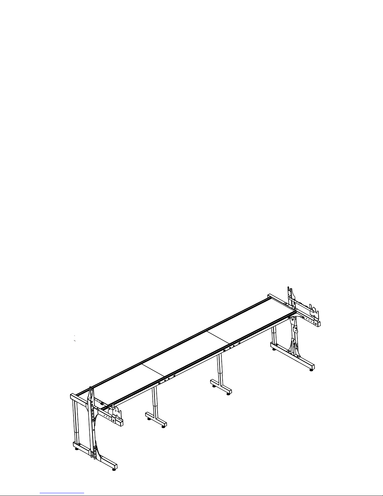
King Quilter Frame Assembly 1
King Quilter Frame
NOVEMBER 2018
Assembly Instructions
Table of Contents
Parts List ..........................................page 2
Preparation: Batting Bar Bracket Assembly, Do this First! ....page 7
Step 1: End Leg Assembly..............................page 8
Step 2: Table Assembly ...............................page 14
Step 3: Center Leg Assembly ...........................page 15
Step 4: End Leg to Table Assembly ......................page 17
Step 5: Precision-Glide Track Assembly .................. page 22
Step 6: Front Pole Carrier / Rear Pole Carrier Arm Assembly . page 25
Step 7: Bungee Cleat Assembly .........................page 26
Step 8: Leveling the Frame.............................page 27
Step 9: Pole Assembly ................................page 28
Step 10: Adding Pole Ends .............................page 29
Step 11: Pole to Frame Assembly ....................... page 31
Step 12: Rubber End Cap Assembly ......................page 32
Step 13: Bungee Clamp Assembly .......................page 33
Step 14: Hook and Loop Strips on Poles Assembly ..........page 34
Step 15: Attach Leaders ..............................page 35
#QF00007-12 and QF00007-10
2 King Quilter Frame Assembly
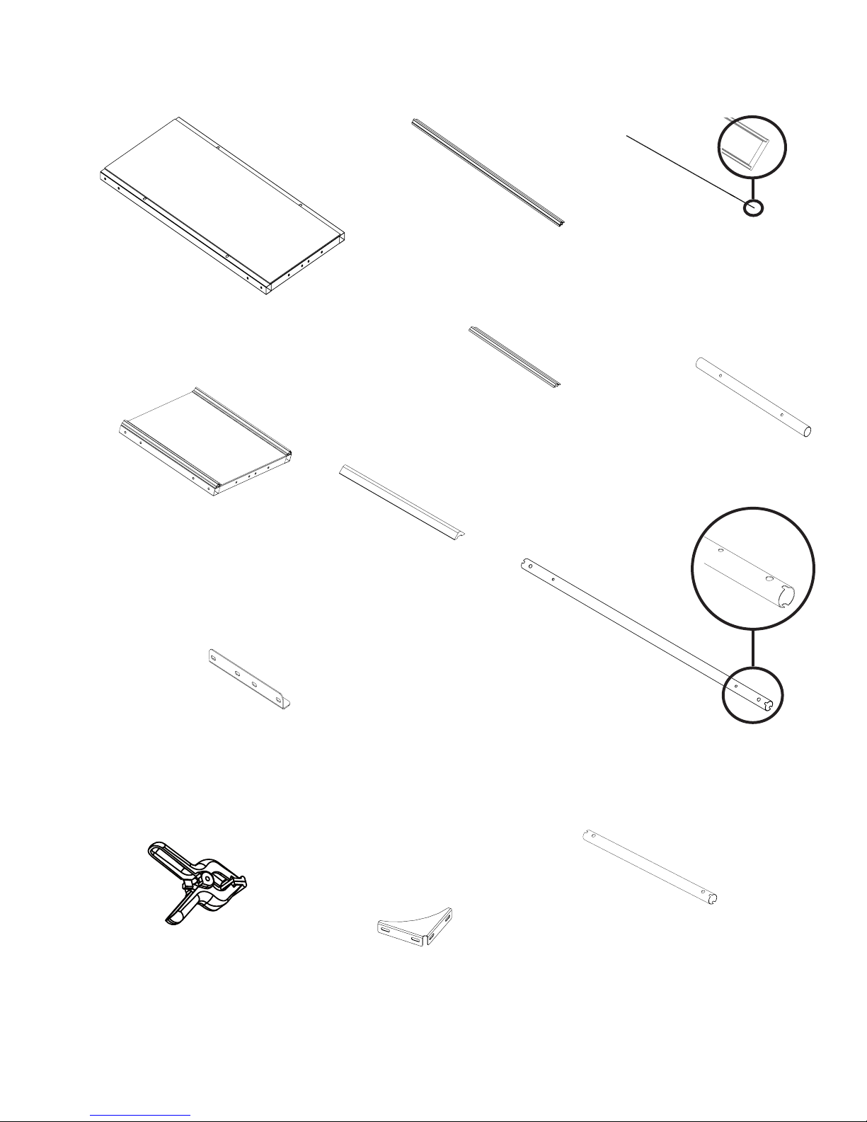
Table Splice Brace (4)
Part# QF09318-05
BOX3
Four Foot Table Section
(3) For 12’ frame,
(2) for 10’ Frame
Part# QF00007-301
BOX 1 & 4
Track Support Coupler (4)
Part# QF09318-03
BOX 3
Bungee Clamp (4)
Part# QF09318-110
BOX 3
4-foot Pole Section
Fifteen come with 12’ frame and ten come with
10’ frame.
Part# QF0007-701
BOX 2 & 4
2-Foot Coupler (10)
Part# QF09318-702
BOX 2
Front Gusset Bracket (2)
Part# QF00007-413
BOX 3
12-foot Black Plastic Track (4)
Part# QF09318-04
BOX 3
4 Foot Track Support Section
(6) For 12’ frame, (4) for 10’ frame
Part# QF09318-02
BOX 1 & 4
SMP QF00007-12 and QF00007-10 Frame Parts List
Two Foot Table Section (1) with
10’ Frame Only
Part# QF00007-302
BOX 4
2-foot Pole Section
Five come with 10’ frame only,
None come with 12’ frame
Part# QF0007-703
BOX 4
2 Foot Track Support Section
(2) For 10’ frame only, (0) come with 12’ Frame
Part# QF09318-02
BOX 4
Leaders - No Image
11’ Leaders for 12’ Frame (1)
Part# QF09580
or
9.5’ Leaders for 10’ Frame (1)
Part# QF09851
BOX 4
King Quilter Frame Assembly 3
SMP QF00007-12 and QF00007-10 Frame Parts List
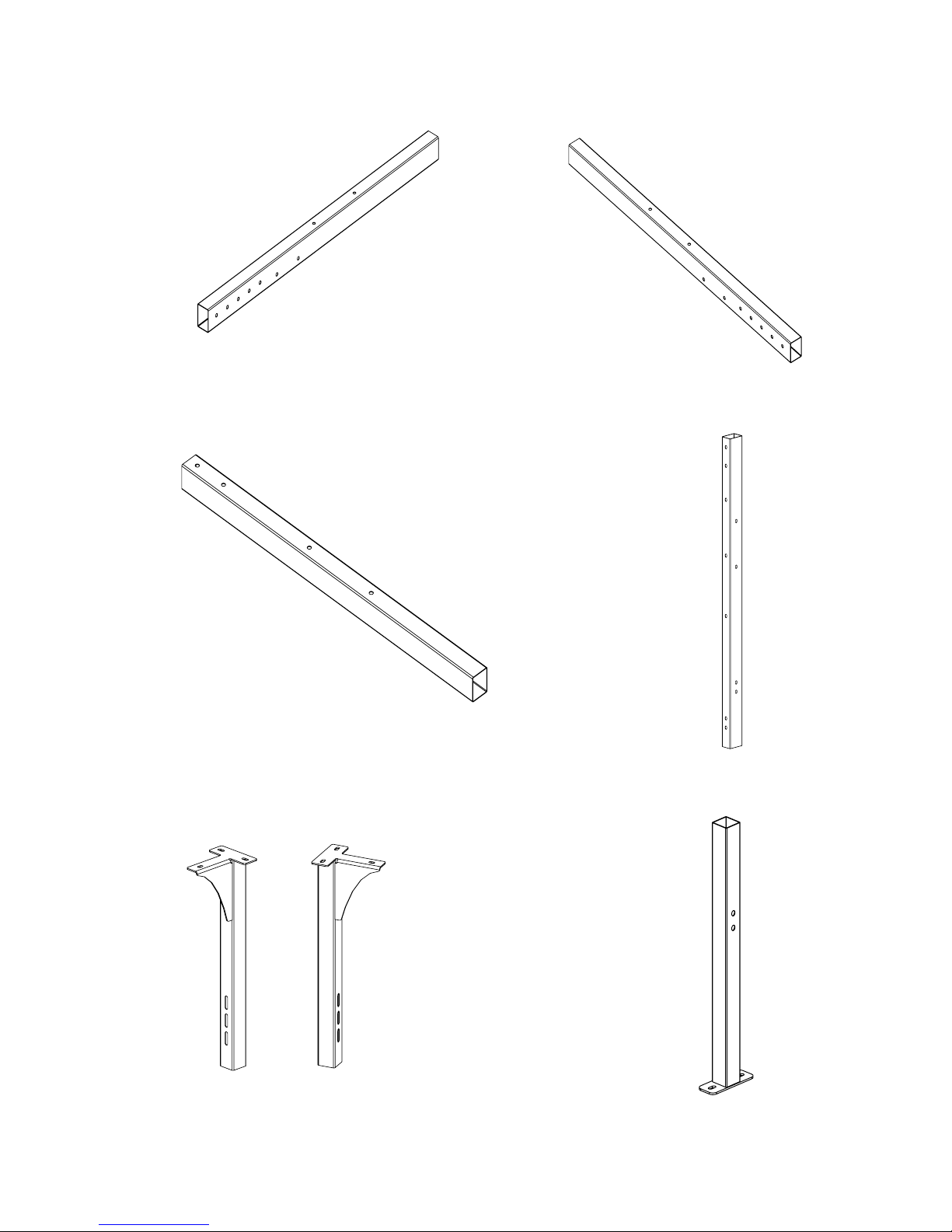
Upper Beam Left Hand Side Leg (1)
QF00007-503
BOX 1
Upper Beam Right Hand Side Leg (1)
QF00007-403
BOX 1
Upright Beam Both Sides (2)
QF00007-402
BOX 1
Lower Beam (Both Sides) (2)
QF00007-401
BOX 1
Inside Left Inside Right
Rear Leg Lower (Both Sides) (2)
QF00007-409
BOX 3
Rear Leg Upper Left (1)
QF00007-508
BOX 3
Rear Leg Upper Right (1)
QF00007-408
BOX 3
Inside Left Inside Right
4 King Quilter Frame Assembly
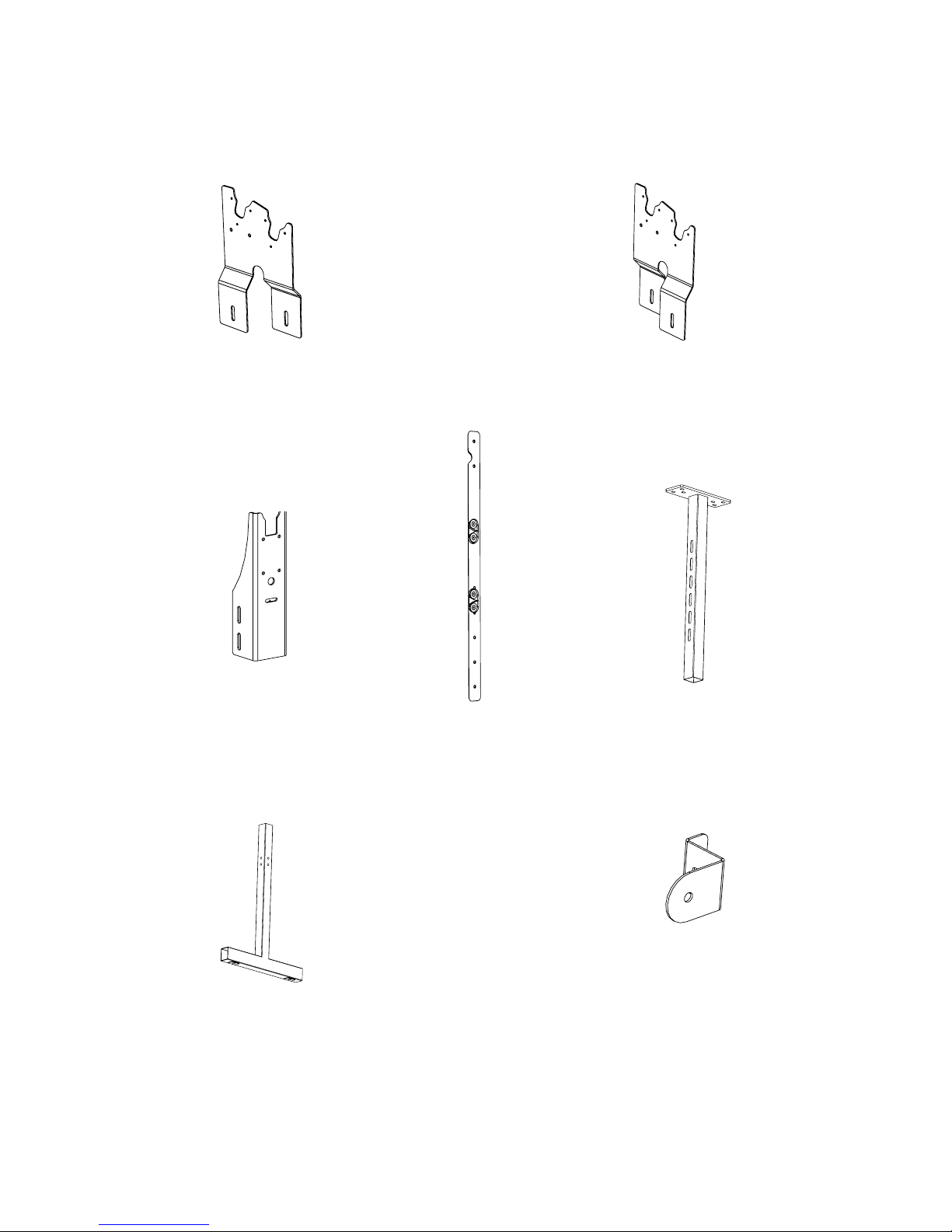
SMP QF00007-12 and QF00007-10 Frame Parts List
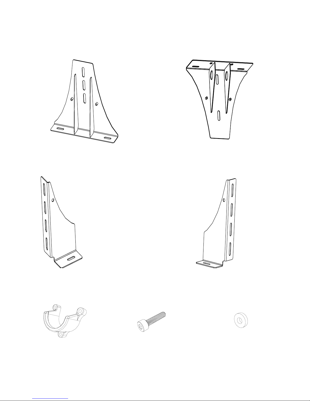
Lower Gusset Bracket (1 per side=2 total)
QF00007-406
BOX 3
Upper Gusset Bracket (1 per side=2 total)
QF00007-407
BOX 3
Outer Side Bracket Left (2 per side= 4 total)
QF00007-405
BOX 3
Outer Side Bracket Right (2 per side=4 total)
QF00007-404
BOX 3
Pole Cradle (3)
QF11038
BOX 3
Screw, M4x18SKC ZN (9)
QF10870
BOX 3
Washer, M4x10 Flat ZN (9)
QF00007-417
BOX 3
King Quilter Frame Assembly 5
SMP QF00007-12 and QF00007-10 Frame Parts List
Front Left Pole Carrier (1)
QF00007-511
BOX 3
Front Right Pole Carrier (1)
QF00007-411
BOX 3
Rear Pole Carrier Arm (2)
QF00007-410
BOX 3
Upper Middle Leg
(2) for 12’ frame, (1) for 10’ frame
QF005300-602
BOX 3
Lower Middle Leg
(2) for 12’ frame, (1) for 10’ frame
QF05300-601
BOX 3
Batting Bar Bracket (2)
QF00007-414
BOX 3
Bungee Cleat Bar (2)
QF00007-412
BOX 3
This manual suits for next models
1
Table of contents


