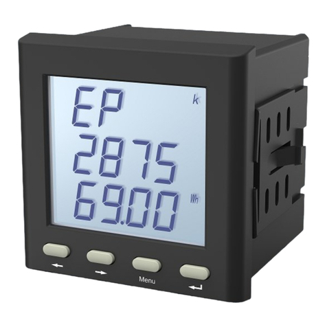
Sfere PD195Z-CD32F User manual

DIN-rail Mounted DC Energy Meter
User Manual
Applied to:
PD195Z-CD32F
JIANGSU SFERE ELECTRIC CO., LTD.

2
Safety instructions
Danger sign is used to warn operation personnel that
there is a danger. If this danger is neglected, injury or
death will occur to personnel, and equipment will be
damaged.
Warning sign is used to call operation personnel’s
attention to take appropriate care measures, otherwise
injury or death will occur to personnel.
CAUTION:
◆Make sure only the qualified technicians perform the installation and
maintenance;
◆Before performing wiring operation to the meter, make sure the input signal and
the power supply are switched off;
◆The proper voltage detecting device should be used to guarantee no voltage in
any part of the meter;
◆The electrical parameters supplied should be within the rated range;
The following situations may result in damages to the meter or cause mistakes in
the operation of the meter.
◆The voltage of the auxiliary power supply goes beyond the rated range.
◆The frequency of the power distribution system goes beyond the rated range.
◆The input polarity of the voltage or the current is incorrect.
◆Remove or connect the communication plugs without powering off.
◆Connect the terminal wires against the related instructions.
Please don’t touch the terminals when the meter is in
operation!

3
Content
Safety instructions ..................................................................................... 2
1. Product introduction ............................................................................. 1
1.1 Overview ......................................................................................1
1.2 Model selection ........................................................................... 1
2. Technical specifications .........................................................................1
3 Installation and Wiring ........................................................................... 3
3.1 Dimension ....................................................................................3
3.2 Wiring .......................................................................................... 3
4 Operation ................................................................................................4
4.1 Panel ............................................................................................ 5
4.2 Display ......................................................................................... 5
4.3 Basic electricity measurement .................................................... 5
4.4 Key icon and function description ...............................................6
4.5 Settings menu overview .............................................................. 7
5 Function ................................................................................................ 10
5.1 Energy pulse output .................................................................. 10
6.1 Physical layer ............................................................................. 11
6.2 Communication protocol ...........................................................11
6.3 Message command format ....................................................... 12
6.4 Data format ............................................................................... 15
Appendix MODBUS-RTU Communication Register Information Table .. 17
Operating data .................................................................................17
Parameter settings .......................................................................... 17

1. Product introduction
1.1 Overview
This DC watt hour meter is applicable to DC charging pile and can (support) measure
the voltage, current, power, electric energy and other parameters of two DC circuits.
It has RS485 communication interface to realize remote data transmission.
1.2 Model selection
Model
Measurements (2 channel)
COMM
Energy
Pulse
U
I
P
E
PD195Z-CD32F
DC 1000V
DC 75mV
●
●
1 loop
2 loops
2. Technical specifications
Electrical character
Accuracy
Active energy Class 1
Data refresh frequency
1s
Measuring
Voltage
Input range
DC 1000V
Measurement
range
50V~1200V
Accuracy
0.2%
Characteristic
consumption<1W,
impedance >1MΩ
Current
Input
DC 75mV
Measurement
range
0.002In~1.2In
Accuracy
0.2%
Power
Accuracy:0.5%
Power supply
Working range
DC20V~36V
Power consumption
≤1W
Communication
RS485interface, Modbus-RTU

2
Baud rate 1200~38400bps
Mechanical character
Protection
IP20
Environmental characteristics
Working temperature
-25~70℃
Storage temperature
-30~70℃
Relative humidity
≤95%RH
Pollution degree
2
Altitude
2000m
Electromagnetic compatibility characteristics
Electrostatic discharge immunity
GB/T 17626.2 IV class
Radio frequency electromagnetic
field radiation immunity
GB/T 17626.3 IV class
Electrical fast transient burst
immunity
GB/T 17626.4 IV class
Surge (impact) immunity
GB/T 17626.5 IV class
Radio interference
GB 9254 B class

3
3 Installation and Wiring
3.1 Dimension
72
90
35
63.5
PD195Z-CD32F
11 12 4
1 2 5958 47 48
U1+ U1- I1+
BA +-
RS485
Power
+ -
49 50
+-
1 2
5
I1-
13 14 6
U2+ U2- I2+
7
I2-
Figure 3-2 PD195Z-CD32F Dimensions
3.2 Wiring
Figure 3-3 PD195Z-CD32F wiring

4
The terminals of the CD32F DC metering module are numbered uniformly, as
shown in the table below:
Power supply
1,2
Auxiliary working power supply
Current signal
4,5,6,7
75mV input
Voltage signal
11,12,13,14
DC voltage input
Energy pulse
47,48,49,50
47 and 49 are the positive terminal of
passive output, which is connected to the
positive terminal of the external power
supply.
RS485
58,59
A+, B-
Instructions:
(1) 1 and 2 are the auxiliary power supply of the instrument, please ensure that
the power supply is suitable for this series of products to prevent damage to the
product.
(2) For the use of the detailed wiring terminals, please connect according to
the wiring diagram on the specific product shell.
(3) The terminal of the current must not be suspended to prevent the wrong
value from being displayed.
(4) Connect the negative terminal of the voltage input to the negative terminal
of the corresponding current shunt.
4 Operation

5
4.1 Panel
PD195Z-CD32F
Figure 4-1 PD195Z-CD32F panel diagram
4.2 Display
AB
C
A: Data (parameter) indication B: Data unit and order of magnitude
C: Data value
The meter uses segment code LCD to display meter information. Contains
information such as the unit, magnitude, type, phase, etc. of the data, as well as
communication instructions.
4.3 Basic electricity measurement
The meter measures electrical parameters such as voltage, current, power, and
electrical energy, which can be viewed on the meter screen, but some parameters
can only be read through communication.
The following table is an example of the display of basic electricity.

6
Voltage
U1=500.0V
Note: When the voltage value is greater
than 21.47MV, it is displayed as FFFF
Current
I1=100.0A
Power
P1=50kW
Positive energy
EP1=1000kwh
Negative energy
EN1=550kwh
4.4 Key icon and function description
The user can set the parameters of the instrument by pressing the keys.
Key icon
Key function description
Move options up / page forward / modify parameters / add

7
selected data bits
Move options down / page back / modify parameters
Return to the previous menu / show options to jump directly
Enter selected options
Value modification method
Press " " to move and modify the data bit, and press " " to increase the
current data bit cyclically.
Enter programming mode
In the measurement display interface, long press the " " key for more than
3 seconds, the meter will display " ", click the " " or " " key to select " ";
press the " " key to enter the password input interface, and enter the password
through the " " or " " key password (the default password is 0001), and then
press the " " key, if the password is correct, you can enter the setting interface.
Exit programming mode
After the data (or options) of the third-level menu is changed, press the " "
key to confirm the change, and press the " " key to exit the change. Press the
" " key to return to the first-level menu, and then press the " " key, the
meter will prompt "save--no", at this time, there are two options:
1) Do not save the setting parameters: press the " " key;
2) Save the setting parameters: press the " " or " " key to select "save--yes",
and then press the " " key;
3) Return to the programming menu: press the " " key
In setting operation: " " key is used for menu switch key and numerical value
left shift, " " key is used for menu switch key, numerical addition and subtraction
and movement of decimal point, " " key is used to return, " " key is used to
enter menu and confirmation after modifying the value.
4.5 Settings menu overview

8
For the detailed description of the setting menu, please refer to the following
description of the character code of the setting menu
First level
Second level
Third level
Code
Desc
riptio
n
Code
Description
Character code / value
Description

9
Syste
m
para
mete
rs
Password
~
Set user
password
Clean energy
Invalid
Valid
inpt
Input
setti
ngs
pt1-1
Circuit 1 primary
voltage
000001~999999
V
pt1-2
Circuit 1 secondary
voltage
000001~999999
V
ct1-1
Circuit 1 primary
current
000001~009999
A
pt2-1
Circuit 2 primary
voltage
000001~999999
V
pt2-2
Circuit 2 secondary
voltage
000001~999999
V
ct2-1
Circuit 2 primary
current
000001~009999
A
Com
muni
catio
n
Meter address
0001~0247
1~247
Baud rate
1200~38400
1200~
38400bps
Data format
N81
n.8.1
O81
o.8.1
E81
e.8.1
N82
n.8.2
Basic parameter settings

10
Example: Set the Modbus address to 12, modify the baud rate to 9600, and
modify the data parity format to even parity. The operations are as follows:
5 Function
5.1 Energy pulse output
The instrument provides 2-way energy pulse output to realize the verification
and remote transmission of power data. The pulse output is a collector-level
open-circuit optocoupler, and a remote computer terminal, PLC, and DI switch
acquisition module can be used to collect the total number of pulses of the
instrument to realize the cumulative measurement of electric energy. The output

11
method used is the method of accuracy inspection of electric energy (National
Metrology Regulations: Pulse Error Comparison Method of Standard Meter).
6 Communication
The instrument has one communication interface by default, and some instruments
can add one communication interface. The communication protocol is Modbus-RTU
6.1 Physical layer
1) RS485 communication interface, asynchronous half-duplex mode;
2) The communication speed can be set from 2400 to 38400 bps, and the factory
default is 9600 bps;
3) Byte transmission format (N81, E81, O81, N82): 1 start bit, 8 data bits, (1 parity
bit), 1/2 stop bit.
6.2 Communication protocol
The instrument supports the standard Modbus-RTU communication protocol.
Structure of the data frame: message format.
Address code
Function code
Data code
Check code
1 byte
1 byte
N bytes
2 bytes
Address code: Slave address, address range 1-247, other addresses are
reserved.
Function code: Indicates what function the addressed terminal performs. The
following table lists the function codes supported by the meter, as well as their
meanings and functions.

12
Code
(hexadecimal)
Significance
03/04
Read data register value
10
Write set register instruction
Data code: It contains the data required by the terminal to perform a specific
function or the data collected when the terminal responds to a query. The contents
of these data may be numerical values, reference addresses or setting values. For
example, the function code tells the terminal to read a register, the data field needs
to indicate which register to start from and how many data to read, and the
returned content of the slave data code includes the data length and corresponding
data.
Check code: The error check (CRC16) field occupies two bytes and contains a
16-bit binary value. The CRC value is calculated by the transmitting device, and then
appended to the data frame. The receiving device recalculates the CRC value when
receiving the data, and then compares it with the received CRC value. If the two
values are not equal, it indicates that an error occurred in the communication .
6.3 Message command format
(1) Read data register value (function code 0x03/0x04)
Request
Frame
structure
Address
code
Function
code
Data code
Check code
Start register
address
Number of
registers
Occupied
bytes
1 byte
1 byte
2 bytes
2 bytes
2 bytes
Data
range
1~247
0x03/0x04
0x0000~0xFFFF
Maximum 125
CRC16
Message
example
0x01
0x03
0x00 0x06
0x00 0x06
0x25C9
Response

13
Frame
structure
Address
code
Function
code
Data code
Check code
Register bytes
Register value
Occupied
bytes
1 byte
1 byte
1 byte
12 bytes
2 bytes
Message
example
0x01
0x03
0x0C
12 bytes of data
CRC16
Note
:
The starting register address requested by the host is the first data address of
the primary grid or secondary grid to be queried, and the number of registers is the
length of the query data. For example, the starting register address "0x00 0x06"
represents the three-phase phase voltage float type data address. The number of
registers "0x00 0x06" means the data length is 6 (3 float data occupies 6 registers).

14
(2) Write setting register instruction (function code 0x10)
Request
Frame
structure
Address
code
Function
code
Data code
Check
code
Register
start
address
Register
length
Register bytes
Write
value
Occupied
bytes
1 byte
1 byte
2 bytes
2 bytes
1 byte
2N
bytes
2 bytes
Data
range
1~247
0x10
0x080A
0x0001
N
CRC16
Message
example
0x01
0x10
0x08 0x0A
0x00 0x01
0x02
0x0064
0x2ED1
Response
Frame
structure
Address
code
Function
code
Data code
Check
code
Register start address
Register length
Occupied
bytes
1 byte
1 byte
2 bytes
2 bytes
2 bytes
Message
example
0x01
0x10
0x08 0x0A
0x00 0x01
0x23AB
Note
:
When writing the setting register, please strictly follow the meter setting
information address table in the meter appendix. Wrong writing to the setting
register may cause the instrument to work abnormally, please operate with caution.

15
6.4 Data format
Some measurement data of the meter provides primary data and secondary
data, such as voltage, current, power, electric energy, etc. There is a proportional
relationship between the two data. For example, the secondary data of voltage
multiplied by the ratio of the voltage transformer equals the primary data, the
secondary data of the current multiplied by the ratio of the current transformer
equals the primary data, and for the power and electric energy data, it needs to be
multiplied by The ratio of voltage and current transformers is equal to the primary
data.
(1) 32bit floating point format
32bit floating point format data follows the IEEE-754 format. The byte order of
the data adopts the big endian method, with the high byte first and the low byte
last.
(2) 16bit integer format
The 16bit integer format data adopts the complement storage method. The
byte order of the data adopts the big endian method, with the high byte first and
the low byte last.
(3) 32bit integer format
The 32bit integer format data adopts the complement storage method. The
Address (Hex)
Data (Hex)
Description
0000-0001
435C-8000
0x435C8000 = 220.5
0002-0003
4360-4CCD
0x43604CCD = 224.3
0004-0005
435E-B333
0x435EB333 = 222.7
Address (Hex)
Data (Hex)
Description
0000
0230
0x0230 = 560
0001
0172
0x0172 = 370
0002
0096
0x0096 = 150

16
byte order of the data adopts the big endian method, with the high byte first and
the low byte last.
Address (Hex)
Data (Hex)
Description
0000-0001
0007-A120
0x0007A120 = 500000
0002-0003
0000-07D0
0x000007D0 = 2000
0004-0005
FFFF-FDF0
0xFFFFFDF0 = -528

17
Appendix MODBUS-RTU Communication Register Information Table
Operating data
Address-HE
X
Address-
DEC
Form
at
Data description
Unit
R/W
0006-0007
6-7
Int32
Circuit 1 voltage
0.1V
R
0008-0009
8-9
Int32
Circuit 1 current
0.1A
R
000A-000B
10-11
Int32
Circuit 1 power
0.1kw
R
000C-000F
12-15
Int64
Circuit 1 positive energy
10wh
R
0010-0013
16-19
Int64
Circuit 1 negative energy
10wh
R
0014-0015
20-21
Int32
Circuit 2 voltage
0.1V
R
0016-0017
22-23
Int32
Circuit 2 current
0.1A
R
0018-0019
24-25
Int32
Circuit 2 power
0.1kw
R
001A-001D
26-29
Int64
Circuit 2 positive energy
10wh
R
001E-0021
30-33
Int64
Circuit 2 negative energy
10wh
R
Parameter settings
Address-HE
X
Address-DE
C
Form
at
Data content
Data description
R/W
0801
2049
Int16
Instrument setting
password
0000-9999
R/W
0804
2052
Int16
High byte: #1 meter
address
1-247
R/W
Low byte: #1 baud
rate
0:1200bps,
1:2400bps,
2:4800bps,
3:9600bps,
4:19200bps,
5:38400bps
0805
2053
Int16
High byte: #1 check
format
0:N,8,1,1:E,8,1
2:O,8,1,3:N,8,2
R/W
Table of contents
Other Sfere Measuring Instrument manuals
