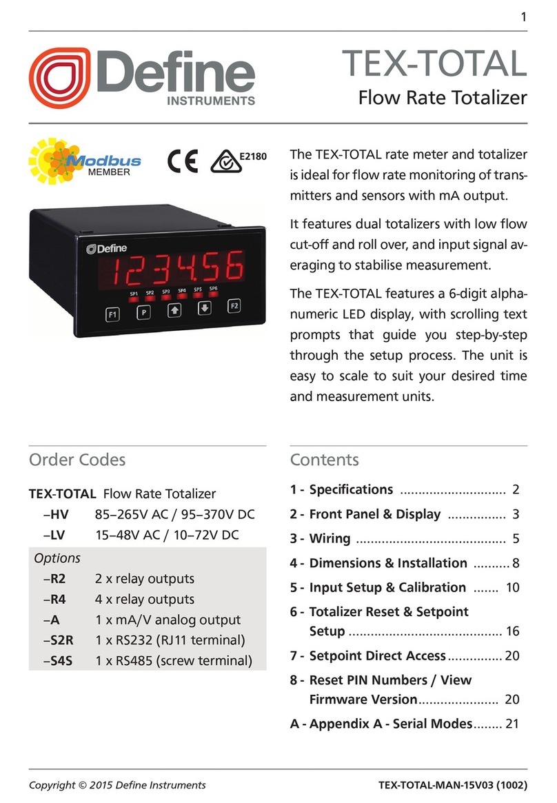
Sfere DGN175 U User manual

User manual
Valid for instruments with version 01.xx
TWO-COLOUR DIGITAL PANEL METERS
Progra
mm
able,
±
10000 point
s
DGN175 U / T / M
ÉTUDES ET RÉALISATIONS
ÉLECTRONIQUES / INSTRUMENTATIONS / AUTOMATISME
Route de Brindas - Parc d’activités Arbora N°2
69510 - Soucieu en Jarrest
Tél. 04 72 31 31 30 - Fax 04 72 31 31 31
Tel. Intern. 33 4 72 31 31 30 - Fax Intern. 33 4 72 31 31 31
SFERE - TA IN/63 -A 03/23- Any data in this documentation may be modified without prior notice.
http://www.ardetem-sfere.com - email : info@sfere-net.com

SUMMARY
1 . INTRODUCTION p2 5 . DIRECT FUNCTIONS p22
2 . DIMENSIONS p5 5.1 Zero reset of the Min / Max. values p22
3 . CONNECTINGS p6 5.2 Display of the direct input measure p22
4 . PROGRAMMING p7 5.3 Zero reset of the alarm recordings p22
4.1 - Communication with the appliance p7 5.4 Quick programming of the alarm setpoints p22
4.2 –Orientation through the programming p7 5.5 Menu adjustment (display calibration) p23
4.3 –Main menu p8 5.6 Menu Tare p24
4.4 –Programming menu p9 5.7 Setting of the brightness of the displays p24
4.4.1 –Programming of the input p9
a / Process signals p9
b / Temperature signals p10
c / Resistive sensors p10
4.4.2 –Programming of the display factor p11
4.4.3 - Programming of the advanced functions p12
4.4.4 –Programming of the analogue output p13
4.4.5 –Programming of the relay outputs p14
4.4.6 –Programming of the RS485 output p16
4.4.7 –Programming of the logic inputs p16
4.4.8 –Programming of the safeties p17
4.4.9 –Programming of the brightness and the leds p18
4.4.10 - Menu save p19
4.5 Programming of the access code p19
4.6 Menu simulation p20
4.7 Menu direct functions p20
4.8 Setting of the keyboard sensitiveness p20
4.9 Menu ABOUT (information about the product) p21
6 . ERROR MESSAGES p25
7 . GENERAL WARRANTY TERMS p25
8 . ANNEXE: MODBUS p26
p1

1. INTRODUCTION
The series DGN175 offers a complete range of highly accurate
programmable digital panel meters. Each appliance is equipped on front
face with a two-colour 4 digits 14 mm high display, with a brightness which
integrates perfectly in applications in industrial control rooms.
They allow the display, the control and the transmission of data from
any measurable magnitudes.
•The DGN175 U (process inputs) includes as standard:
A bidirectional DC current or voltage input:
±20mA, ±100mV, ±1V, ±10V, ±150V, ±300V.
- Measurable scale overrange from -10% to +10%
- Scale factor programmable
- Enlarging effect
- Extraction of the square root
- Special linearisation in 20 points
- Supply for 2 or 3-wire sensor
•The DGN175 T (temperature input) includes as standard:
A thermocouple input:
(J, K, B, R, S, T, E, N, L, W/G, W3/D, W5/C)
A sensor input: Pt 100 , Ni 100
- Wiring in 2, 3 or 4 wire.
2-wire Pt100 measurement
•The DGN175 M (universal input) includes as standard:
The inputs of the DGN175 U and T plus:
A resistive sensor input: Calibers 0-400 and 0-10 k
A potentiometer input: from 100 to 10 k
AVAILABLE OPTIONS: (to be specified on the order)
Isolated analogue output: A
Active current output: A1
Passive current output: A2
Voltage output: A3
Scale ratio programmable with enlarging effect.
Relay outputs:R or R4
2 or 4 relays: mode setpoint or window.
Recording of the alarms.
Time delay and hysteresis adjustable on each setpoint.
Alarm messages.
Isolated digital output: N
RS 485 2-wire, protocol MODBUS-JBUS.
Logic input (signal 24 VDC): T
2 isolated logic inputs à with programmable functions:
Display hold.
Moving of the decimal point.
Tare function.
Min. Max. zero reset.
Bargraph (16 leds display): B
Allow a quick evaluation of the measured value variations.
Scale factor programmable.
p2

Programming
•With the keyboard
•With the configuration software SlimSET
CODING:
Type: DGN175 M A1R4N RG
Inputs:
Process DGN175 U
Temperature DGN175 T
Universal DGN175 M
Options:
A: Isolated analogue output A1 activecurrent
A2 passive current
A3 voltage
R: 2 Relays
R4: 4 Relays
N: Digital RS485 isolated
T: 2 logic inputs (24VDC) isolated
B: 16 leds bargraph display
The outputs can be combined except for the configuration: AR4NT
Colour code:
RG: Two-colour display Red/Green
RW: Two-colour display Red/White
p3
To communicate with the DGN175 you will need a connection cable C1-µUSB (USB type A male to µUSB type B male.
To connect this cable to the DGN175 insert the µUSB contact into the provided female connector (on the side of the appliance). Then
connect the USB cable to a PC.
The software SlimSET allows the reading of the measuresor the modification of the digital panel meter configuration.
Each configuration is kept as a file stored on disk.
These files can be consulted, modified, duplicated or loaded into the digtal panel meters.
The files can be created with or without having a digital panel meter connected.
All files can be edited on any type of printer.

Features of the inputs
DGN
175 U
DGN
175 T
DGN
175 M
Types
of inputs
Measure range adjustable
from:
Permanent
overload
Intrinsic
error
Input
impedance
mA
-22 to +22mA
±100mA
<
±0.05%
of the MR
Drop 0.9V
m
ax.
mV (1)
-110 to +110mV
±1V
1 M
V
-1.1 to +1.1 V
±50V
-11 to +11V
-165 to +165 V
±300V
-300 to +300V
Thermocouples
(1)
Standard IEC 581
J
K
B
R
S
T
E
N
L
W or G
W3 or D
W5 or C
°C
-160/1200
-270/1370
200/1820
-50/1770
-50/1770
-270/410
-120/1000
0/1300
-150/910
1000/230
0
0/2480
0/2300
°F
-256/2192
-454/2498
392/3308
-58/3218
-58/3218
-454/770
-184/1832
-32/2372
-238/1670
1832
/
4172
32/4496
32/4172
-
(3)
<±0.1%
of the MR, or
30µV typical
(60µV max.)
1 M
Pt100
sensor
(1) (2)
Standard
IEC 751
(DIN 43760)
°C
-200/850
°F
-328/1562
-
<±0.1%
of the MR
Current
250µA
Ni100 sensor
(1) (2)
-60/260
-76/500
-
Differential measures from 2
sensors
Pt100Ω
2-wire StandardIEC751
(1)
-200/270
-328/518
-
Resistivesensors
Calibers0-400
and
0-10 k
<±0.1%
of the MR
Max. current
250µA
Potentiometer
from 100
to
10 k
Max. voltage
100mV
Supply for 2 or
3-wire sensor
24 VDC ±15% with protection from short-circuits.
25 mA max.
Special linearisation up
to
20 points
On inputs: mV, V, mA.
resistive sensors and potentiometer
Extraction of the square root
On mV, V or mA inputs
(1) Sensor break detection
mA input (if down scale ≥3,5 mA
Other inputs: a 12 µA pulsed current allows the detection
of line or sensor break.
(2) Wiring in 2, 3 or 4 wire possible.
The influence of the line resistance (0<Rl<25Ω) is
included in the announced intrinsic error (wiring in 3 or 4
wire).
(3) Efficiency of the CJC (-20°C to 60°C)
Internal CJC:
±
1°C
±
0.03°C/°C
MR: Measure Range
Dérive thermique < 150 ppm / °C
p4

Features of the outputs
General features
Galvanic isolation
:
3 kV-50 Hz - 1 min between supply, inputs, analogue output, relay outputs, RS485 output
and logic input. 1.5 Kv between analogue output and RS485.
Power supply:
Average response time: 150 ms (for a variation of the input signal from 10 to 90 %).
Measure:
•Standard sampling time: 100 ms
•Common mode rejection rate: 130 dB
•Serial mode rejection rate: 50 dB 50/60 Hz
•Zero drift compensation
Use:
•Operating temperature: -20 to 60°C
•Storage temperature: -20 to 70°C
•Use in pollution degree 2 and voltage surge category II or better.
•Max. altitude: 2000m.
Compliance with standards:
•Directive LV 2014/35/UE……………EN 61010-1
•Directive EMC 2014/30/UE…………EN 61326-1
•Directive ROHS 2011/65/UE
Protection:
Front face : IP 65
Case: IP20
Terminals: IP 20
Housing:
Self-extinguishing case of
black UL 94 V0 ABS.
PC UL94 V0 front face.
Mounting on panel with
tightening by 4 screw
pads.
Connectors removable terminal blocks
on rear face for screwed connections
(2.5mm², flexible or rigid)
Display: ±10 000 points (14 mm)
Electroluminescent red and green (orred
andwhite)
Alarm leds + 2 leds with programmable
functions
Dimensions of the case
96 x 48 x 119.4 mm
(with terminals)
43
Mounting on panel
Cut out 43 x 91.2 mm
43
91,2 ± 0,2
± 0,2
Isolated digital comms RS485
Protocol MODBUS/JBUS (EIA RS485)
External seal
Case
tightenings
p5
2. DIMENSIONS
Max. operating range
Consumption
20 to250 VAC - 50/60Hz and
3 W max.
20 to 250 VDC
6 VA max.
Types
of OUTPUTS
2 setpoint per relay, configurable on the whole MR
.
Hysteresis programmable
Time delay programmable from 0 to 999.9 sec.
8A/250 VAC on resistive load
2 or 4 change-over relays
Voltage: Direct or reversed 0-10V
ILoad impedance
Rc 5k
Votage
Load impedance
Rc
600
Current: Direct or reversed 0-20mA
Current
Isolated analogue
output
Features

A B C D
3. CONNECTINGS
Location of the terminals
(view of case rear side)
INPUTS
OUTPUTS
1 2 3 4 5 6 7 8 9 10 11 12 13 14 15
A
G
F
or
26
27
28
20
21
22
23
24
25
LOGIC INPUTS
LOGIC INPUTS
SUPPLY
PROCESS
B
RESISTANCE AND POTENTIOMETER
2-wire
transmitter
3-wire
transmitter
2-wire
3-wire
2-wire
3-wire
4-wire
4-wire
Potentiometer
RELAIS 1 et 2
C
F
E
RS485
G
D
ANALOGUE OUTPUT
mA active (A1)
mA passive (A2)
p6
RELAYS 1 AND 2
RELAYS 3 AND 4
OFF1
ON1
OFF2
ON2
ON3
OFF3
ON4
OFF4
G
E
F

4. PROGRAMMING
4.1 Communication with the instrument
Several functions can be accessed from the measure display:
Alarms
Relay 1
4.2 Orientation through the programming
The dialogue is ensured by 4 keys located on the front face.
Move through the menus:
downwards move, or
decrease the value
shown.
M
Move through the menus:
upwards move, or increase
the value shown.
Validation of the displayed
parameter, or access to a submenu
More functions can be accessed by pressing several keys
simultaneously:
+
+
+
+
+
Entering of a parameter:
Reading convention:
Move through the main menu
Back to the previous menu
Alternating information display
Display of the
measure
Access to
the main
menu p6
Min. and
Max. 0
reset
p19
Direct access to the menu Adjust.
0 reset of the alarm recordings.
Visualisation of the direct measure.
Direct access to the menu setting of the alarm setpoints
Direct access to the menu TARE.
Note: In mode programming, the instrument will automatically revert to
the measure with the previous configuration, if no key is pressed during 1
min.
and
First start by increasing or decreasing
the 1st digit and the sign: from -9 to +9.
The 2nd from 0 to 9
The 3rd from 0 to 9
The 4th from 0 to 9
Min. value
display
Max.
value
display
Key Unlock: Keyboard
locked if the led is lit.
To unlock it, keep
pressing until the
message U.bloc
appears.
Led 5
and
Led 6
Relay 2
Exit from a submenu to access the
next menu / access to the
programming exit menu.
Between each entering, validate
the cipher by pressing
- For a signed value the entering begins with the choice of the sign (- or 0 = +).
- For a value with decimals, the entering ends by the choice of the position of
the decimal point, which can be moved by .
The display blinks when a choice is possible, or during the
setting of a value.
P7
Relay 4
Relay 3
6520
6528
6588
6888

4.3 Main menu
Simulation of
the input, the
display or the
analogue
output.
(see p20)
Authorized by
access code
Scrolling of
the menus
Vertical move /
Validation
Upwards move /
Increase
Downwards move /
Decrease
Menu exit / access
Move through the menus:
rEAd
PrOG
P.COdE
SINUL
FUnCt
SEnS
AbOUt
Mode reading of the
configuration: Access to the same
menus as for the menu PrOG
without access code and without
any possibility to modify the
programming.
Programming of
the access code
(see p19)
Access to the
list of the direct
functions
(see p20)
Access to the
menu setting of
the keyboard
sensitiveness
(see p20)
Access to the
menu
information
about the
product (see
p21)
CodE
0000
If code correct,
access to the
programming
menu (see p9)
Entering of the access code.
The access to the programming menu is
protected by a 4-cipher code.
The code is 0000 on factory exit
(to change the code, see page 19)
p8
gOOd

4.4 Programming menu (depending on options)
Access to the programming of the input p9
Access to the programming of the display factor p11
Access to the programming of the advanced functions p12
Access to the programming of the analogue output p13
(option analogue output)
Access to the programming of the relays p14
(option relay outputs)
Access to the communication parameters p16
(option digital output)
Access to the programming of the logic inputs p16
Access to the programming of the display: p18
Leds, brightness, colour of the digits…
a. Process signals
Access to the menu exit from the programming with or p19
without saving the configuration
Note:
Press to come back to the menu
Inmode programming,the instrument will automatically come back to the
measure with the previous configuration if no key is pressed during 1min.
SAV
E
To the menu dISPL
Choice of the voltage caliber.
Current
Voltage
Ds.In
U
FS.In
00.00
00.00
InPut
DIsPL.
CF.AdV
AnA
rELAy
SECU.
Pr.dIS
SAVE
p9
InPut
To t° sensors and
resistive sensors
InPut
NA
U
100NU
U
1U
10U
270U
150U
Setting of the input down
and up scale:
-22 < x < 22 (mA)
-110 < x < 110 (100mV)
-1.1 < x < 1.1 (1V)
-11 < x < 11 (10V)
-165 < x < 165 (150V)
-300 < x < 300 (270V)
JBuS
tOr
Access to the programming of the analogue and relay p17
outputs in case of self-diagnosis error and/or sensor
break, and access to disabling the sensor break detection
(option analogue output and/or relay outputs)
4.4.1 Programming of the input
(DGN175 U and M)

b. Temperature sensors (DGN175 T and M) c. Resistive sensors (DGN175 M)
tC-L
tC-C5
tC-C3
tC-n
tC-C
To the menu dISPL
00.00
InPut
p10
Temp.
rES
Process
signals
° C
° F
Pt100
nI100
d. Pt
3 Cab.
2 Cab.
4 Cab.
tC
tC-j
tC-CA
tC-S
tC-r
tC-t
tC-E
400
10000
3 Cab.
2 Cab.
4 Cab.
Ds.In
U
FS.In
Pot.
Ds.In
U
FS.In
Choice of
the
sensor
Type of
Thermocouple
J
K
S
R
T
E
B
N
W (or G)
W3 (or D)
W5 (or C)
L
00.00
00.00
00.00
tC-b
Setting of the input down
and up scale:
0 < x < 440 (400 Ohms)
0 < x < 11000 (10 kOhms)
Choice of
the unit
Choice of the
resistor wiring
type: 2, 3 or 4
wire.
Choice of the
resistor wiring
type: 2, 3 or 4
wire.
Choice of
the caliber
Resistor
Potentiometer
Delta
Pt100
Setting of the input
down and up scale:
0 < x < 100 %

pOInt
00.00
0.1°
1°
D.DISp
L
f.DISp
L
00.00
00.00
Setting of the display
factor:
To the menu CF.AdV
If temperature input (DGN175 T and M)
Choice of the display
resolution.
Choice of the decimal
point position:
Display for the
input down scale
dS.In
Display for the
input up scale
FS.In
0 to 3 decimals
p11
DIsPL.
DISpL.
4.4.2 Programming of the display factor

To the menu ANA
Function extraction of the square root
(mV, V or mA inputs).
√ of the measure brought back in % of the
programmed measure range.
Eg.: Input 4-20 mA 12 mA gives 0.707 (√0.5).
Special linearisation:
Recording of an unlinear curve
programmable in X and in Y.
Maximum: 20 points.
Number of points:
from 3 to 20
Programming of the abscises
in electrical values of the input.
Programming of the ordinates
in display value.
0.5%
1%
2%
5%
10%
25%
50%
100%
*If input other than Temperature
Coeff. Sec.
0 0.15
1 0.4
2 0.7
3 1
4 1.8
5 2.5
6 3
7 3.5
8 4
9 5
10 6
4.4.3 Programming of the advanced functions
CF.AdV
Typical response time
according to the coefficient
(for a variation from 10 to
90% of the input signal):
CF.AdV
Percentage of the measure
variation on which the filter
will be active:
FunCt
LInEA
A
rOOt
LiSPE
nb.PtS
0003
000.00
AbSC.
OrdI.
A00
00.00
A01
Y00
Y01
00.00
CUt
nO
Yes
fiLt
COEFF.
0
rAnGE
100
Linear
Programming of
the Cut-off
Value in display
points.
Programming of the
digital filtering in case
of unsteady input.
Coefficient:
from 0 to 10.
If = 0
If ≠0
Cut: Value below which
the display will be held at
the down scale
*
*
p12

4.4.4 Programming of the analogue output (if option)
Or
To the menu RELAY.
Choice of the limitation type on the output:
Std: output between 0 (mA or V) and 110%
of the programmed value (dS.OUt or
FS.OUt).
Max: 22 mA or 11 V
SCALE: Output limited to the programmed
dS.OUt and FS.OUt values.
*
p13
AnA
AnA
tYpe
Out. I
Out. U
Ds.OUt
00.00
Fs.OUt
DO.dIS
t
FO.dIS
00.00
00.00
00.00
LIN
SCALE
Std.
Indication of the output type
(current or voltage).
Setting of the analogue output
down and up scale:
00.00 < x < 22.00 (mA)
00.00 < x < 11.00 (V)
Display corresponding to the
output down scale.
Down
Up
Display corresponding to the
output up scale.
*The return values (for sensor break or error self-diagnosis)
will not take the limitation of the output into account.

4.4.5 Programming of the relay outputs (if option)
AL.LED
OFF
On
NENO
NESS
OFF
rELAy
rELAY
reL1
reL2
ALArN
On
OFF
NOdE
p14
SPT.1
On
SPT.2
00.00
00.00
HYST
00.00
DeLAY
T.OFF
00000
DOUbL.
SINpL.
000.0
To rEL3 and rEL4 if option available, otherwise to the menu SECU.
L__
__j
J L
I I
OFF
On
De-activated
Activated
Mode setpoint:
Access to SPt.1
Mode window:
Access to SPt.1 and SPt.2
Setting of the setpoint:
Choice of the
operating mode:
Mode window only
MANDATORY: SPt.2 > SPt.1
Setting of the hysteresis
0 < HYSt < 9999 in display points.
From 0 to
999.9 sec.
Choice of the status of the led when relay activated:
ON: led on
OFF: led off
Function recording of the alarm:
Function display of an alarm message:
Enter 5 characters.
Idem rEL1
rEL 2
Setting of the time delay:

OFF
ON
setpoint
SPt.1
ON
OFF
setpoint
SPt.1
SPt.1
SPt.2
setpt
OF
F
ON
ON
setpt
SPt.2
SPt.1
ON
OFF
OFF
setpoints
Setting of the time lapse from 0 to 999.9 sec.
dOUbL: time delay on the alarm triggering and switch off
SIMPL: time delay on the alarm triggering only
Mode setpoint
or
or
Mode window
ON: coil supplied
OFF: coil not supplied
HYST
Setting of the hysteresis
The hysteresis is activated on switching from led on to led off, that
is to say on switching off alarm, since the led represents the alarm
status.
Mode setpoint
Mode window:
There are 2 ways to adjust setpoints:
- Either in mode programming entering the correct access code.
- Or by pressing simultaneously and if the access to a quick
programming has been authorized on the programming of the code (see p19)
SPt.1
SPt.1
- HYSt
Led on
Led off
SPt.1
SPt.1
- HYSt
Led off
Led on
Led off
SPt.2
SPt.2
+ HYSt
Time delay on the alarm
DeLAY
Choice of the led status
AL.LED
Choice of the status of the LED associated with the relay when the
relay coil is supplied.
Recording of the alarm
NENO
Allows recording the alarm after a setpoint has been passed. When the
measure comes back below the alarm setpoint, the relay remains on and the
led blinks to warn the user that the setpoint has been passed (for the reset to 0
of the alarm recordings see the menu CLr.AL in the direct functions).
Note: An exit from the mode programming with saving of the
configuration will reset the alarm recordings to 0.
Display of alarm messages
NESS
A programmed alarm message can be made to appear alternating with the
measure.
The message will appear only during the alarm, that is to say while the
associated led is on.
p15
Setting of the alarm setpoints

Transmission rank of the bytes inside an integer:
H-L: MSB transmitted first
L-H: LSB transmitted first
Time delay before any response:
OFF: Typical delay 10 ms
On: Typical delay 75 ms
See the menus tOr
or SECU
TOr 2
n0
tArE
HOLd
CLr.N
nO: No action.
FCt.P: Function moving of the decimal point (enter the position).
CLrM: Function 0 reset of the min. and max.
HOLd: Function display hold.
tArE: Function tare (process, resistance and potentiometer inputs).
To the menu SECU
p16
See the features of the digital data link p26
Input signal 24 VDC
Choice of the action in case of activation of the logic input 1:
Choice of the action in case of activation of the logic input 2:
*Function HOLd: In case of activation of the logic input
the display and the analogue output will remain fixed
even if the input signal varies.
The relays will carry on reacting to the input signal.
*
4.4.6 Programming of the RS485 output (option)
Communication parameters
JbuS
SLAUE
00O0
bAUd
Slave numbers
Transmission speed:
9600
19200
Must be between 1 and 255.
PArIt.
nOnE
eUEn
Odd
FOrN.
H-L
L-H
dELAY
OFF
On
JbuS
1200
2400
4800
4.4.7 Programming of the logic inputs (option TOR)
tOr
TOr 1
tOr
FCt.P
n0
tArE
HOLd
CLr.N
--.--
Choice of the parity:
nOnE
EVEn
Odd
*

p17
SeCU.
rUPt.
detEC.
reL.1
ReL.2
Off
HI
LO
Out.
Off
rEPLI
00.00
DIag.
reL.1
Out.
Off
rEPLI
00.00
OFF
On
Status of the relay 2 in case of sensor break:
*
Off
HI
LO
Off
HI
LO
ReL.2
Off
HI
LO
To the menu Pr.DIS
Disconnecting of the
sensor break
detection.
Inactive relay active relay de-activated
Status of the relay 2 in case of error:
Inactive relais active relay de-activated
See the self-diagnosis error codes p25
Detection of the sensor break on the inputs: mV,
temperature, resistance (<400Ω) or mA (if the down
and up scale < 3.5 mA)
*Idem for the relays 3 and 4 (if option 4 relays)
If mV or temperature input
Status of the relay 1 in case of sensor break:
*
Inactive relay active relay de-activated
Inactive relay active relay de-activated
Programming of a fallback value:
00.00 < x < 22.00 (mA)
00.00 < x < 11.00 (V)
Status of the analogue output in case of sensor break.
Inactive
Programming of a fallback
value:
00.00 < x < 22.00 (mA)
00.,00 < x < 11.00 (V)
dEtEC.: In mV or temperature input, the sensor break detection
can be disabled in order not to disturb some calibrators swhich
may be sensitive to the sensor break detection current.
Self-diagnosis: The digital panel meter permanently watches its
components for any drifts. The self-diagnosis serves to warn the
user in case of abnormal increase of these drifts before they may
provoque false measures.
Status of the relay 1 in case of error:
Status of the analogue output in case of self-
diagnosis error.
Inactive
Menu can vary depending on the input type and the output options
4.4.8 Safeties Menu programming of the safety functions: Sensor break / self-diagnosis
SECU.

p18
Pr.dIS
4.4.9 Programming of the leds, the brightness and the colour of the displays
Pr.DIS
Y
Br.dIG
LEU.3
Br.LEd
LEU.3
COLOr
COL.1
COL.2
CHgT.
nO
On AL.
HI
dIAG.
LdIG.
On
OFF
Inf.
NIddL.
HIGH
SEnS.
nULL
YES
nO
nO
LEd 5
tOr 1
TArE
nO
Led 6
To the menu SAVE
Status of the last digit (right hand side).
Setting of the brightness of the displays:
Setting of the brightness of the leds:
4 levels: LEV.0 to LEV.3
4 levels: LEV.0 to LEV.3
Choice of the basic colour.
2 versions available:
Red/Green or Red/ White
Condition for colour switch.
No colour
switch.
Colour switch if
an alarm is
triggered.
Colour switch if
an error is
detected.
OFF: enforced to 0
On: not enforced to 0
Display of the unsignificant zeros (on the left).
Setting of the keyboard sensitiveness:
3 levels:
Low, Middle or High
Choice of the function associated with the led 5:
Choice of the function associated with the led 6:
nO: No attribution.
tArE: Led on if a tare has been recorded.
tOr 1: Led on if logic input 1 activated.
tOr 1: Led on if logic input 2 activated.
rS: Led on in case of transmission on the RS485.
AdJ: Led on if a calibration of the input has been
recorded (temperature input only).
Example: measured value: 0015
YES: the display will show 0015
nO: the display will show 15
d.BArG
0000
F.BArG
0000
Display corresponding to 100% of the bargraph.
Display corresponding to 0% of the bargraph.
*
*If option bargraph
*
tOr 2
rS
AdJ.
tOr 1
TArE
tOr 2
rS
AdJ.

p19
4.4.10 Exit from the programming with or without saving
SAVE
SAVE
YES
nO
4.5 Menu programming of the code
P.CodE
COdE
ACtIU.
EnAbL.
dISAb.
n.COdE
0000
p.CodE
f.COdE
SINUL.
YES
nO
Prg.AL
SAVE
CLr.AL
ADjUS.
tArE
YES
nO
0000
G00D
Entering of the
new code.
Saving
YES: Exit and save the configuration
nO: Exit without saving the configuration
Note: An exit with saving of the configuration will
automatically reset to 0 the la tare, the min. and the max.
as well as the alarm recordings.
Back to the measure
display.
If access locked by code.
Activation of the code.
De-activated
Active
Output
New code
Choice of the functions for which the access will be locked by code:
YES: Code entering needed to access
the function.
nO: Free access to the function.
YES: Saving of the programming of the
functions locked by code.
*If option Relays
*
*
This manual suits for next models
2
Table of contents
Other Sfere Measuring Instrument manuals

