SGK Pearl Joint KC Series User manual
1
Instruction Manual
No. : SE20019-0
Issued on : Mar. 16 2020
Pearl Rotary Joint
KC Series
This instruction manual applies to products with type designations
that begin with KC, or SKCL.
Pearl is a trade name of Showa Giken Industrial Co., Ltd.
This instruction manual describes important precautions for preventing
accidents and how to handle the product. To ensure safe use, be sure to
read this manual and fully understand its contents before using this product.
Store this manual carefully so that it can be referred to at any time.

2
Table of Contents
1. How to Read Nameplate (Nameplate Information) …………………………………………… P3
2. For Safety ……………………………………………………………………………………… P3
2‐1)Symbols …………………………………………………………………………………… P3
2‐2)For safe use ……………………………………………………………………………… P3
3. Product Overview ……………………………………………………………………………… P4
3‐1)Application ………………………………………………………………………………… P4
3‐2)Information indicated by model names …………………………………………………… P4
3‐3)Service conditions ………………………………………………………………………… P5
3‐4)Precautions for use ………………………………………………………………………… P5
3‐5)Product structures and materials ………………………………………………………… P6
3‐6)Product dimensions ………………………………………………………………………… P7
3‐7)Product masses …………………………………………………………………………… P7
3‐8)Accessories ………………………………………………………………………………… P8
4. Transport and Storage ………………………………………………………………………… P9
4‐1)Transport …………………………………………………………………………………… P9
4‐2)Storage ……………………………………………………………………………………… P9
5. Installation to Machinery ……………………………………………………………………… P9
5‐1)Internal pipe (for duplex only) ……………………………………………………………… P9
5‐2)Installing to a roll ………………………………………………………………………… P10
5‐3)Pipe laying ………………………………………………………………………………… P11
6. Removal from Machinery ……………………………………………………………………… P12
7. Operation ……………………………………………………………………………………… P13
7‐1)Operation …………………………………………………………………………………… P13
7‐2)Operation shutdown ……………………………………………………………………… P13
8. Inspection and Maintenance …………………………………………………………………… P14
8‐1)Daily inspection …………………………………………………………………………… P14
8‐2)Greasing …………………………………………………………………………………… P14
8‐3)Repair and replacement of consumables ………………………………………………… P15
9. Troubleshooting ………………………………………………………………………………… P16
10. Disposal ……………………………………………………………………………………… P17
11. Product Warranty …………………………………………………………………………… P17
A. Appendix - How to Repair or Replace Consumables ………………………………………… P19
A‐1)For simplex (KCL, KCLF, SKCL) …………………………………………………………… P1
A‐2)For duplex, stationary IP, thread connection (KC) ……………………………………… P20
A‐3)For duplex, rotational IP, flange connection (KCF) ……………………………………… P22
A‐4)For duplex, rotational IP (KCW, KCFW) ……………………………………………………… P24
P3
P3
P3
P3
P4
P4
P4
P6
P6
P7
P7
P7
P8
P9
P9
P9
P9
P9
P10
P11
P12
P13
P13
P13
P14
P14
P14
P14
P15
P16
P16
P19
P20
P22
P24
P26
3
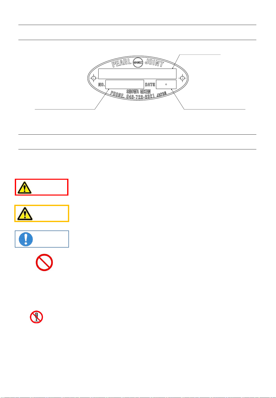
The nameplate attached to the product indicates the model name, manufacturing
number, and manufacturing date.
1. How to Read Nameplate (Nameplate Information)
2. For Safety
2‐1) Symbols
The symbols used in this instruction manual are described below.
Indicates that failure to follow the warning message may cause bodily
accidents that may result in serious or even fatal injury.
Indicates that failure to follow the caution message may cause
personal injury or damage to peripheral equipment.
Indicates that failure to follow the instruction message may cause
reduced product lifetime, product damage, or early leakage.
Indicates “prohibited actions”.
2‐2) For safe use
1. Transport, storage, installation, piping, operation, or maintenance of this product should be
carried out by an experienced expert.
2. Be sure to observe all warnings, cautions, and instructions described in each section.
3. Never disassemble or modify this product because doing so is dangerous. We shall assume
no responsibility for any malfunctions, accidents, or the results thereof involving a
reassembled product after disassembly or a modified product. Also, a reassembled product after
disassembly or a modified product shall not be covered by the product warranty even if the
warranty period is still valid. This also applies to repairs done by yourself.
4. Confirm specifications (dimensions, materials, masses) indicated on individual product drawings
before staring work. Contact our sales representative for requests for product drawings.
5. Always use the latest instruction manual. You can download the latest version from our website.
WARNING
CAUTION
Instruction
Manufacturing Date
Model Name
Manufacturing No.
4
●For installation with a taper thread or a flange
3. Product Overview
3‐1) Application
A rotary joint is used for supplying fluid to or draining it from a machine rotating part called a
roll, drum or cylinder, via fixed pipes.
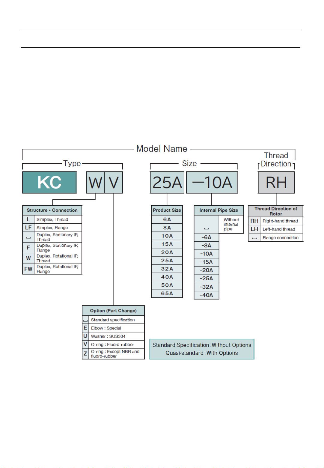
3‐2) Information indicated by model names
Information indicated by KC series model names is described below.
The product list is shown in our catalog or on our website.
Note 1) “␣” indicates a space. A model name is indicated without spaces.
2) If two or more option (part change) codes are selected, they are indicated in alphabetical
order.
3) The selection of two or more options resulting in a long model name is indicated as type
“OKC****” to denote a customized product for administrative reasons.
(The asterisks (****) indicate a four-digit number allocated to each model.)
If you have any questions, contact our sales representative.
5
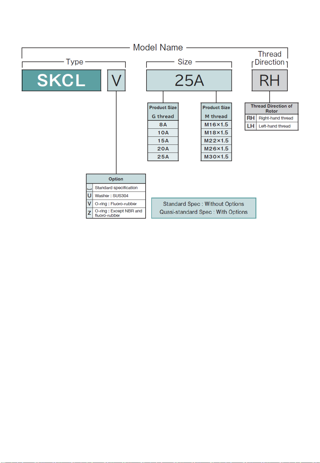
●For installation with a parallel thread (simplex only)
Note 1) “␣” indicates a space. A model name is indicated without spaces.
2) If two or more option (part change) codes are selected, they are indicated in alphabetical
order.
3) The selection of two or more options resulting in a long model name is indicated as type
“OKC****” to denote a customized product for administrative reasons. (The asterisks
(****) indicate a four-digit number allocated to each model.))
If you have any questions, contact our sales representative.
6
3‐4)Precautions for use
Use this product by following the warnings and instructions described below.
Note ) The lowest pressure when used under a pressure lower than atmospheric pressure is 1.3 kPa abs (10 Torr).
3‐3) Service conditions
Service Conditions of KC Series
WARNING
1. If flammable fluids leak and ignite, bodily accidents including serious or
even fatal injury, or accidents that damage peripheral equipment may
occur due to explosion or fire. Depending on the type of fluid, this
product may subject to restrictions due to national laws or local
regulations.
2. This product cannot be used for food-processing machinery.
Doing so may lead to adverse health effects.
Instruction
1. Perform operation within the service conditions.
2. Do not operate under conditions where both pressure and rotation speed
are close to the max. values. Doing so significantly reduces product
lifetime.
3. This product cannot be used in temperature conditions where the
product ambient temperature exceeds the upper limit of the service
conditions.
4. The product cannot be used for liquid containing solid particles (slurry)
or pulverulent body. The product cannot be used for fluid that causes
corrosion on it.
5. This product cannot be used for operation with no rotation,
intermittent rotation, or low-rotation speed (a few rotations per minute).
Otherwise, fluid leakage may occur.
Pressure
Rotation speed Temperature
(MPa)
(min-1)(℃)
6A~25A 1,500
32A~65A 1,000
Max.
KC
Air / Gas / Water / Oil
0.98
100
Series
Fluid
Size
7
The casing is finished with alumite
treatment (anodizing).
KC
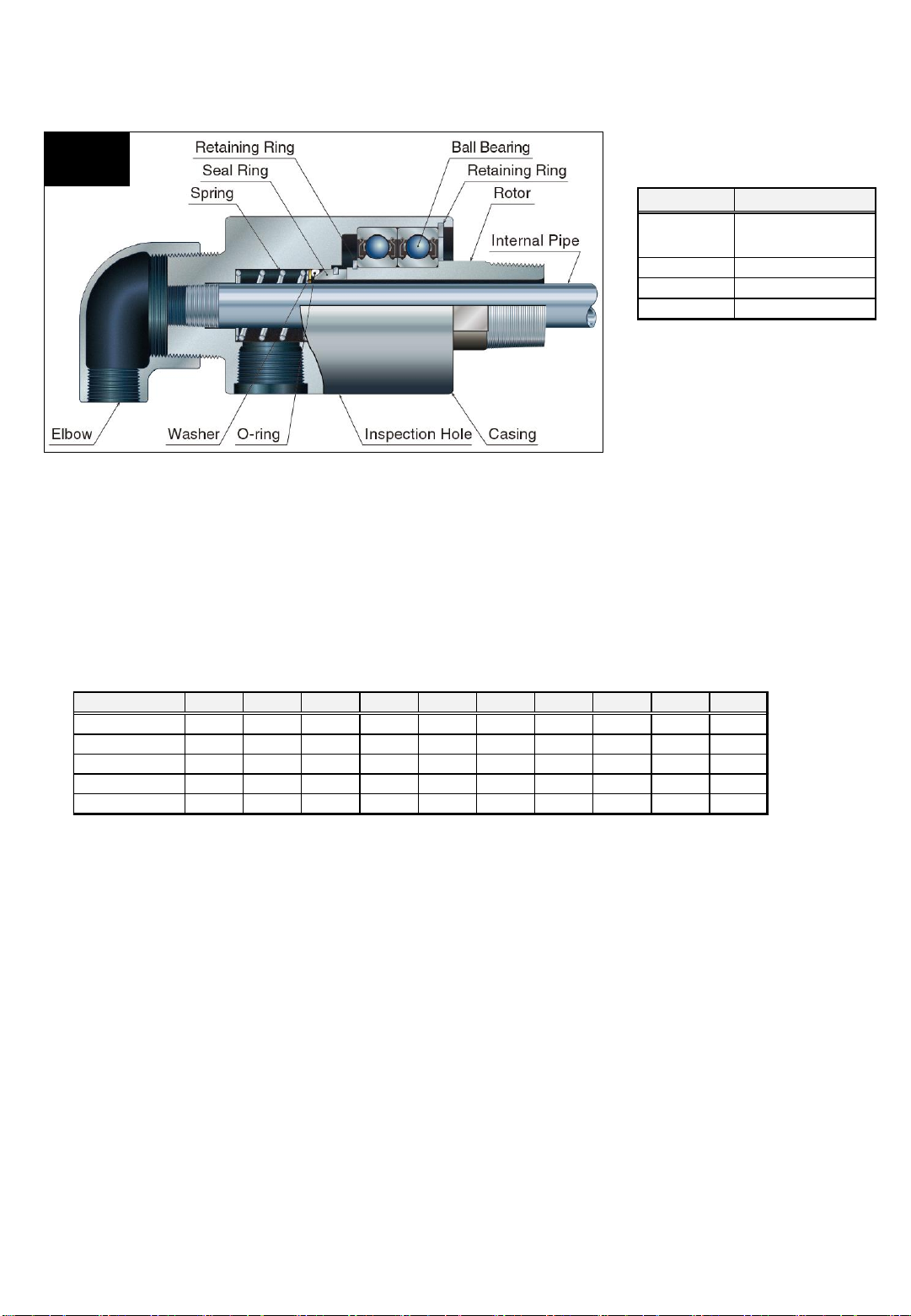
3‐5) Product structures and materials
Note ) Component materials are indicated on product drawings.
Contact our sales representative for requests for product drawings.
Materials of Main Components
(Standard Specification)
3‐6) Product dimensions
Product dimensions are shown on product drawings, in our catalog, or on our website.
3‐7) Product masses
(kg)
Masses of KC Series
Type 6A 8A 10A 15A 20A 25A 32A 40A 50A 65A
KCL 0.15 0.25 0.37 0.60 0.85 1.2 2.3 2.6 5.3 9.6
KCLF - - 0.90 0.90 1.25 1.7 3.0 3.3 6.6 10.9
KC/KCW - - - 0.75 1.05 1.5 2.6 2.9 6.5 10.6
KCF/KCFW - - - 1.05 1.45 2.0 3.3 3.6 7.8 11.9
SKCL - 0.25 0.37 0.60 0.85 1.2 - - - -
Part Name Material
Rotor
Stainless Steel
Carbon Steel
Casing Aluminum Alloy
Seal Ring Carbon
O-ring NBR
8
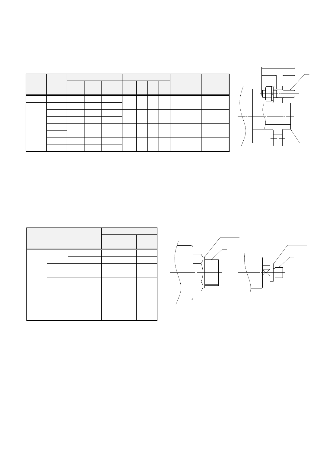
3‐8)Accessories
1. A product installed with a flange is supplied with a gasket (copper jacket) and four sets of a stud
bolt (SS400), a hex. nut (SS400), and a spring washer (SWRH).
2. A duplex, stationary IP, flange connection product (KCF) is supplied with a lock nut (right-hand
thread, SS400) used for securing the internal pipe.
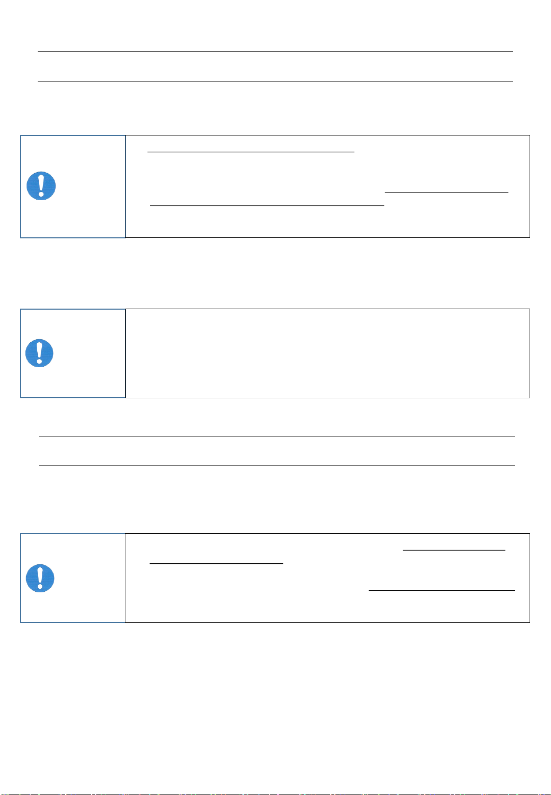
3. A product installed with a parallel thread (SKCL) is supplied with a gasket (copper plate).
(mm)
(mm)
Accessories
(Installation with parallel thread)
Accessories(Flange Connection)
K
ab
L
Gasket
KCLF 10A 24 16 3.2
15A 24 16 3.2
20A 29 20 3.2
25A 34 26 3.2
32A
40A
50A 64 50 3.2
65A 79 62 3.2
KCLF
KCF
KCFW
M10
45
15
20
M12
58
18
27
49
37
3.2
M10
48
15
20
M12 type1
M12 No.2
M10 type1
Spring
Washer
M8 No.2
M10 type1
M10 No.2
M10 No.2
M8
36
11
18
M8 type1
Type
Size
Gasket
Stud Bolt
Hex. Nut
Outer
Dia.
Inner
Dia.
Thick-
ness
K
L
a
b
G1/4 22 13.5 2
M16×1.5 23 16.3 2
G3/8 26 17 2
M18×1.5 24 18.5 2
G1/2 30 21.3 2
M22×1.5 27.5 22.2 2
G3/4
M26×1.5
G1 39.5 33.5 2
M30×1.5 39 30.5 2
2
25A
Outer
Dia.
Inner
Dia.
Thick-
ness
Size
A
Gasket
35
26.8
SKCL
8A
10A
15A
20A
Type
A
A
8A10A~25A
Gasket
Gasket
9
●Duplex, stationary IP, thread connection (KC)
Screw the internal pipe taper thread into the head. For standard specification products, the
thread directions of the rotor and internal pipe are the same. Depending on the customer’s
request, the thread directions of the rotor and internal pipe may be different from each other.
Check the thread directions on the product drawings, etc. before installation.
●Duplex, stationary IP, flange connection (KCF)
Screw G thread (right-hand thread) of the internal pipe into the head, and then secure it with a
supplied lock nut.
Instruction
1. Do not subject the product to undue impact while it is being transported.
Falling down or impact causes product damage (seal ring, etc.) or early
leakage. If the product fell down or was damaged, contact us for maintenance.
2. When transporting a product with an internal pipe, do not secure the product
so that load is directly applied to the internal pipe. Doing so may bend the
internal pipe, hindering installation to a roll. Moreover, abnormal noise or early
leakage may result after installation.
4. Transport and Storage
4‐1) Transport
Transport this product by following the instructions described below.
4‐2) Storage
An improper storage method causes product damage or early leakage.
Store this product by following the instructions described below.
Instruction
1. Wrap the product before storing it to prevent the entry of foreign objects.
2. Store this product in a dry environment at 10℃ to 40℃.
3. The storage period should be within two years. If the storage period exceeds
two years, contact us for maintenance.
4. If the product is stored after use, clean and then store it under the above
conditions.
5. Installation to Machinery
5‐1) Internal pipe (for duplex only)
Install an internal pipe to the product according to the following instructions.
Product adjustment is not required before installation.
Instruction
1. When inserting an internal pipe into the product rotor, be careful so that the
pipe does not hit inner parts. Failure to do so could cause inner part damage,
resulting in fluid leakage.
2. When installing an internal pipe to the product, be careful not to bend the pipe.
If it is bent, product installation to a roll may be hindered. Also, vibration or
abnormal noise after installation, or early leakage may result.

10
5‐2) Installing to a roll
Install the product by following the cautions and instructions described below.
WARNING
Be sure to install the product so that an inspection hole faces downward.
Also, do not block the hole. This hole is used for detecting leakage at an
early stage. If this hole is directed toward other directions or is blocked,
leakage cannot be detected at an early stage. Moreover, leaked fluid may
accumulate in a casing and boll bearings may be damaged, causing serious
bodily accidents due to resulting rotation failure.
CAUTION In order to prevent injuries, take the product weight into consideration
before installing the product. Use equipment such as a crane as necessary.
This work should be performed by two or more persons.
Instruction
1. Remove any foreign objects in such flow passages as a pipe or a roll before
product installation. If the fluid contains foreign objects, install a strainer at
the flow passages. Foreign objects cause early leakage.
2. If the product is installed with its center misaligned or tilted, vibration or
abnormal noise may result. Moreover, the product or machine equipment may
be damaged due to vibration.
3. When tightening screws or nuts, properly torque-tighten them according to the
screw type or size.
4. To prevent uneven tightening, evenly tighten flange screws in a cross pattern.
5. Perform retightening after the start of use.
6. To prevent internal pipe damage, do not hook a sling wire rope to an
internal pipe. Hook a sling wire rope to a casing.
●Installation: taper thread
1. Wrap seal tape around the taper thread of the rotor.
2. Use the shank on the rotor to screw the product into a roll.
●Installation: parallel thread
1. Install the supplied gasket to the rotor.
2. Use the shank on the rotor to screw the product into a roll.
●Installation: flange
1. Install the supplied stud bolts to a roll.
2. Install the supplied gasket to a roll socket.
3. Insert the rotor spigot into the roll socket while checking that the stud bolts go through the rotor
flange holes.
4. Set spring washers on the stud bolts, and then secure the product with the supplied nuts.
11
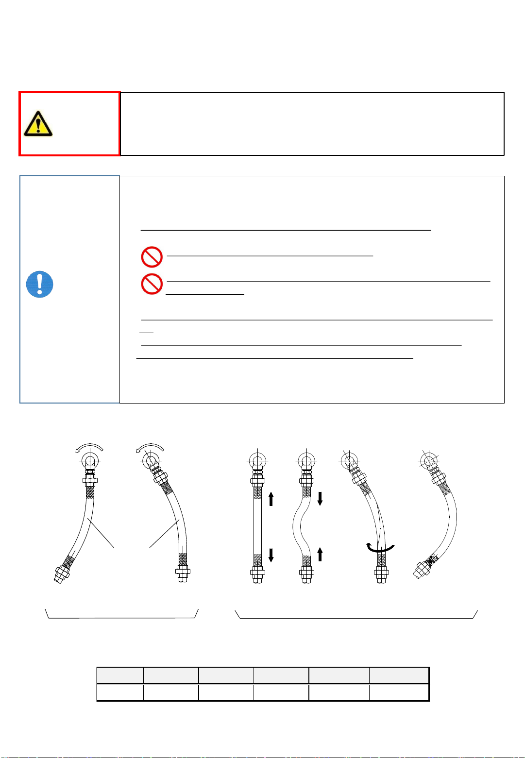
(mm)
サイズ 6A~20A 25A 32A/40A 50A 65A
長さ 300~400 400~500 600~800 900~1000 1200~1300
5‐3) Pipe laying
Perform pipe laying work by following the warnings and instructions described below.
WARNING
Use a hose for product connection suitable for characteristics of fluid used
and operating conditions (pressure, temperature). If an unsuitable hose is
used, it may be damaged, causing injury to workers or damage to peripheral
equipment.
Instruction
Observe the following instructions to prevent the generation of force applied to
the sides of the product, possibly causing product damage or early leakage.
1. Use a flexible metal tube or rubber hose with adequate flexibility.
2. Steel pipes should not be used for pipe laying.
3. Avoid such pipe laying where heavy items such as valves are suspended
from the product.
4. When installing a flexible metal tube, slightly bend it in the rotation direction of
roll. (See the bottom left figure.)
5. Carry out pipe laying work so that excessive “tension”, “compression”,
“torsion”, or “bending” is not applied to a flexible metal tube. In particular,
“torsion” may significantly reduce the lifetime of the flexible metal tube.
(See the bottom right figure.)
6. Use the following table as a guideline for the flexible metal tube length.
Flexible
Metal Tube
Rotation Direction of Rroll
Slightly bend the tube
in the rotation direction. Tension Torsion Bending
OK NG
Compression
Flexible Metal Tube Length (Guideline)

12
6. Removal from Machinery
Remove the product by following the warnings, cautions, and instructions described
below in reverse order of the installation.
WARNING In order to prevent bodily accidents due to residual fluid in the product or
pipes, remove the product after fluid has been completely drained from the
product or pipes and temperature has dropped to room temperature.
CAUTIION In order to prevent injuries, take the product weight into consideration
before removing the product. Use equipment such as a crane as necessary.
This work should be performed by two or more persons.
Instruction To prevent internal pipe damage, do not hook a sling wire rope to an internal
pipe. Hook a sling wire rope to a casing.

13
7. Operation
7‐1) Operation
Perform operation by following the warnings, cautions, and instructions described below.
7‐2) Operation shutdown
Follow the following instructions during operation shutdown.
WARNING Immediately stop operation if fluid leakage is detected during operation.
If operation is continued with fluid leakage not being repaired, serious
accidents including bodily accidents may result.
CAUTION During rotation or high-temperature/pressure fluid flow, keep well
away from the product to prevent injuries or burns. Do not directly
touch rotating or hot parts during operation.
Instruction
1. When starting operation, check for abnormal rotation (center runout, abnormal
noise, etc.) or fluid leakage from the product while gradually increasing fluid
pressure and roll rotational velocity.
2. If operation is continued under a center runout condition, product damage or
fluid leakage may result.
3. The occurrence of surging or water hammer can cause product damage or fluid
leakage. Avoid such occurrence.
4. Do not perform dry operation (operation without fluid flow) for a long time.
The product lifetime becomes shortened.
5. If the fluid is air, add oil mist to the air.
Instruction
1. If the product is left as is for a long time during operation shutdown, rust may
occur, causing fluid leakage after operation restart. Clean flow passages for the
product, pipes, and roll before restarting operation.
2. If water is used as the fluid, take a measure to prevent water from freezing in
the product. Freezing may cause product damage, resulting in fluid leakage after
operation restart.
3. Do not put your hand on or ride on the product during equipment
maintenance. Doing so may cause product damage or fluid leakage after
operation restart.

14
8‐2) Greasing
As grease-sealed ball bearings are used, greasing is not required.
8‐3) Repair and replacement of consumables
The ball bearings and the seal face of the seal ring become worn over the course of operation time.
O-rings also deteriorate. Moreover, if the internal pipe rotates in the product, bearings that support
the pipe also become worn. Then such malfunctions as fluid leakage may occur. However, the product
can be reused by repairing or replacing worn or deteriorated parts.
Contact us for repair or parts replacement. We carry it out according to our repair program.
Depending on the products, expenses for purchasing new products may be lower than repair expenses.
Consult with us when requesting repair or replacement.
< When carrying out repair or replacement of consumables by yourself >
・Repair or replacement should be carried out by an experienced expert.
・Perform work according to “A. Appendix - How to Repair or Replace Consumables".
・Use our genuine parts as replacement parts.
Contact our sales representative to request genuine parts.
・Properly dispose of waste resulting from work according to national laws or local government
regulations or ordinances.
(Attention)
If you carry out repair or replacement, we shall assume no responsibility for any product
malfunctions, equipment malfunctions or accidents resulting from such product or the results
thereof. Also, the product shall not be covered by the product warranty even if the warranty
period is still valid.
8. Inspection and Maintenance
8‐1) Daily inspection
Perform inspection according to the following instructions.
Instruction 1. Visually check pipe connections, product connections, and the product for fluid
leakage. If leakage is detected, repair the product or replace it with a new one.
2. When replacing, use the same type of product with the same size.
15
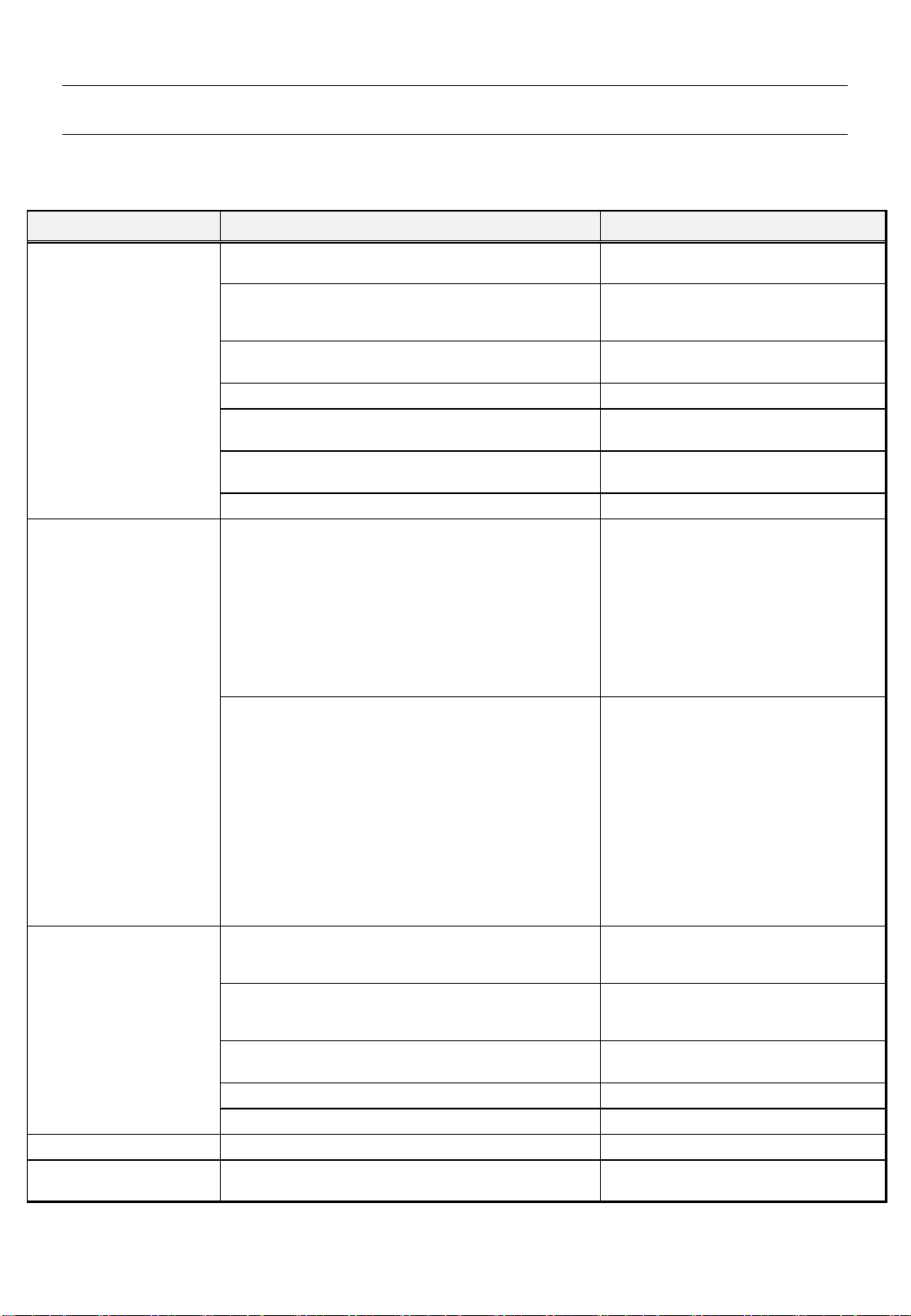
9. Troubleshooting
This section describes the possible causes of and countermeasures against malfunctions.
If a problem persists, contact our sales representative for assistance.
Malfunctions Causes Countermeasures
A load is applied to the product due to an improper
method of pipe laying.
Review the pipe laying method.
The seal ring is damaged.
The seal ring lifetime has been reached.
The rotor seal face is damaged.
Contact us for repair.
The fluid contains foreign objects.
Clean the inside of the product, pipes, and
roll. Install a strainer.
The O-ring adheres to the casing. Contact us for repair.
Operation is performed without rotation, or operation
occasionally ceases during the operation cycle.
Consult with us.
Operation is performed at low-rotation speed (a few
rotations per minute).
Consult with us.
Improper product selection. Consult with us.
The rotation axes of a roll and the product are
misaligned with each other.
-
<Flange connection type> <Flange connection type>
The shaft end socket of a roll is offset from the roll
rotation axis.
Repair the spigot /socket.
<Thread connection type> <Thread connection type>
The shaft end screw hole of a roll is offset from the roll
rotation axis.
Repair the screw hole.
The rotation axes of a roll and the product are inclined
from each other.
-
<Flange connection type> <Flange connection type>
The shaft end socket of a roll is offset from the roll
rotation axis.
Repair the installation face on the roll side
to which the product is installed.
Uneven tightening of fixing screws. Evenly tighten the fixing screws.
<Thread connection type> <Thread connection type>
The center lines of screw holes for fixing the product
are inclined from the roll rotation axis.
Repair the screw hole.
The product is screwed in diagonally. Reinstall the product.
The internal pipe bends and comes in contact with the
inner perimeter of the product rotor or that of the roll
shaft.
Straighten the bent internal pipe.
The internal pipe bent by its weight comes in contact
with the inner perimeter of the product rotor or that of
the roll shaft.
Consult with us.
A load is applied to the product due to an improper
method of pipe laying.
Review the pipe laying method.
Ball bearings are damaged. Contact us for repair.
A sliding sound is heard from the seal face. No fault is indicated.
The rotor does not rotate. A ball bearing does not rotate. Contact us for repair.
Oil is leaking from a ball
bearing.
Oil released from the grease seeps. No fault is indicated.
Noise occurs.
Fluid is leaking from the
inspection hole.
The product has center
runout. (It is vibrating.)

16
10. Disposal
When disposing of packaging materials or products, properly dispose of them according to
national laws or local government regulations or ordinances.
11. Product Warranty
If a malfunction occurs during the warranty period, contact us or the distributor and send the
product to us. Be sure to carefully pack the product for protection before sending it.
After receiving the product, we will confirm the malfunction. If the malfunction was clearly caused
by the materials of product components or the manufacturing method, we will repair the product
in question or replace it with a new one free of charge.
1. Warranty period
<New products>
One (1) year and six (6) months after shipment (from the manufacturing date) or one (1) year
after installation, whichever comes first.
<Repaired products>
Six (6) months after shipment (from the manufacturing date).
2. We charge a fee for repairs in any of the following cases.
①Failure after the warranty period has expired
②Failure caused by use of the product deviating from the service conditions
③Failure caused by misuse
(improper storage, installation, pipe laying, operation or maintenance, etc.)
④Failure caused by fluid contaminants or foreign objects in the fluid
⑤Failure caused by relocation, transport, or falling of the product after delivery
⑥Failure caused by disassembly, repair, or modification done by personnel other than our service
personnel
⑦Failure of the product attributed to using materials or according to standards specified by the
customer
⑧Failure of the product attributed to using materials provided by the customer
⑨Failure caused due to unavoidable acts of nature such as fires or other natural disasters
3. Scope of responsibility
Our responsibility shall be limited to repairs, replacements, or transport expenses covered by this
product warranty provision. Expenses or damages caused by said failures above shall not be
covered.
4. Applicable regions
This product warranty provision shall be applicable to products installed in Japan.
5. Another agreement
If another product warranty agreement is made separately with us and clearly states that said
agreement shall have priority over this product warranty provision, this provision shall not be
applicable.
6. This product warranty provision shall not restrict the customer's legal rights.
Product Warranty Provision

17
Blank Page
18
Export Department Phone : +81-3-3598-1400 Fax. : +81-3-3598-2700
Headquarters 7-24, Nishi-Kobari, Ina-Machi, Saitama, 362-0811 Japan
Phone : +81-48-728-9460 Fax. : +81-48-728-9461
Tokyo Sales Office 2-64-11, Akabane, Kita-ku, Tokyo, 115-0045 Japan
Phone : +81-3-3598-1400 Fax. : +81-3-3598-2700
Osaka Sales Office 2-9-7, Toyosaki, Kita-ku, Osaka, 531-0072 Japan
Phone : +81-6-6371-8341 Fax. +81-6-6371-6283
Nagoya Sales Office 1-107, Takaharidai, Meito-ku, Nagoya, 465-0054 Japan
Phone : +81-52-701-4068 Fax. : +81-52-704-4051
URL http://www.sgk-p.co.jp

19
A. Appendix - How to Repair or Replace Consumables
154263789
Inspection Hole
20
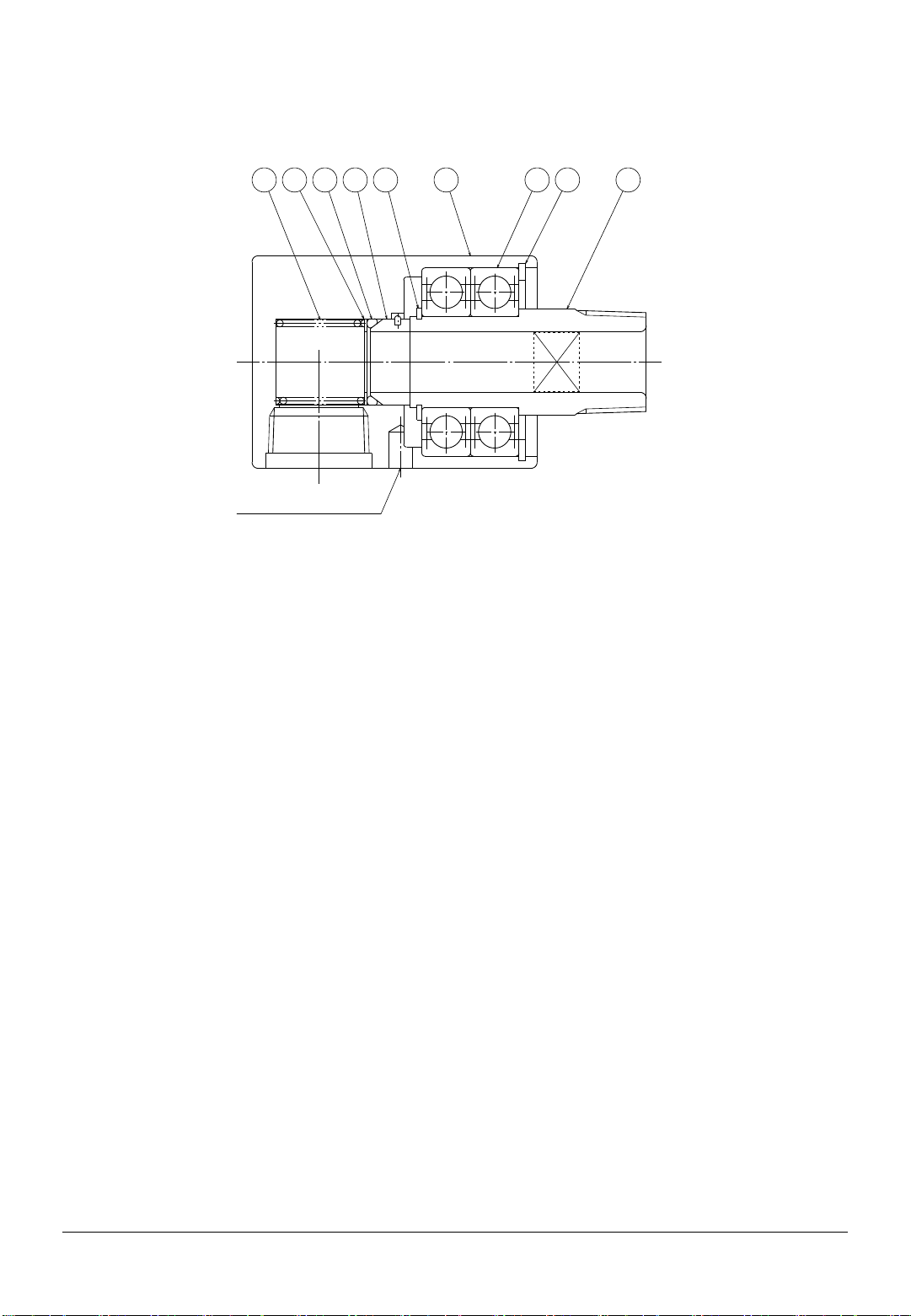
A‐1) For simplex (KCL, KCLF, SKCL)
An explanation is given below with reference to KCL (figure shown below).
The same workflow is applied to KCLF and SKCL.
①Rotor ②Casing ③Seal Ring ④Ball Bearing ⑤Retaining Ring
⑥Retaining Ring ⑦O-ring ⑧Washer ⑨Spring
< Disassembly >
Carefully disassemble the product so that each part is not damaged. In particular, be careful not to
damage the seal faces of rotor ①and seal ring ③.
1) Disconnect all pipes, etc. connected to the product.
2) Clamp casing ②with a vice, etc. so that rotor ①faces upward.
3) Remove retaining ring ⑤.
4) Pull out the assembly consisting of rotor ①, ball bearings ④, retaining ring ⑥(hereinafter called
the rotor assembly) from casing ②.
5) Remove seal ring ③, O-ring ⑦, washer ⑧, and spring ⑨from casing ②.
6) Remove retaining ring ⑥from rotor ①, and then pull out ball bearings ④.
7-24, Nishi-Kobari, Ina-Machi, Saitama, 362-0811 Japan
Phone : +81-48-728-9460 Fax. : +81-48-728-9461
SHOWA GIKEN INDUSTRIAL CO., LTD
http://www.sgk-p.co.jp
This manual suits for next models
7
Table of contents


